Ferrari EF Series User manual

MVA 02 rev 5 - December 2017
1 of 120
Axial fans
Warnings and instructions for use
Translation from the original language

2 of 120
MVA 02 rev 5 - December 2017
Excerpt from the Declaration of Conformity
DECLARATION OF CONFORMITY
Pursuant to Annex IIA of Machinery Directive 2006/42/EC
The Manufacturer: Ferrari Ventilatori Industriali S.p.A.
Via Marchetti, 28
36071 Arzignano (VI) –Italy
DECLARES
under its own responsibility that the machine denominated “industrial fan”:
Ferrari Ventilatori Industriali S.p.A
36071 Arzignano (Vicenza)
Via Marchetti, 28
Tel. +39 0444 471100
Fax +39 0444 471105
http://www.ferrariventilatori.it

MVA 02 rev 5 - December 2017
3 of 120
Main Index
1INTRODUCTION 9
1.1 Purpose of this manual 9
1.2 Safety symbols used in this manual 9
1.3 Safety symbols used on fans 10
2GENERAL INFORMATION 11
2.1 Definitions, basic principles, terminology used and correlated documents 11
2.2 Construction details of axial fans 12
2.2.1 Versions and motor positions 12
2.2.2 Flow indications 12
2.3 Fan identification 13
2.4 Description of fan 14
2.5 Envisaged use and foreseeable uses according to experience, and prohibited uses 15
2.6 Life cycle of fan 16
3WARNINGS AND MAIN SAFETY INDICATIONS 17
3.1 Installation instructions: general information 17
3.2 Installation type A: Instructions for assembly, installation and connections 19
3.3 Installation type B: Instructions for assembly, installation and connections 22
3.4 Installation type C: Instructions for assembly, installation and connections 23
3.5 Assembly and fastener diagrams for fixing guards 24
3.6 Installation type D: Instructions for assembly, installation and connections 28
3.7 Risks involved in foreseeable incorrect handling and/or abnormal uses based on
experience 29
3.8 Other risks related to fans pursuant to UNI EN ISO 12499 30
3.8.1 Specific risks with fans during installation 30
3.8.2 Specific risks with fans during maintenance 30
3.8.3 Environmental risks 31
3.8.4 Vibration risks 31
3.8.5 Operating speed risks 32
3.8.6 Noise emission risks 34
3.8.7 General information on noise emission data 36
4TRANSPORT, MOVEMENT AND STORAGE 42
4.1 Lifting and movement 42
4.2 General warnings for lifting separate fan parts 42
4.3 Fan lifting instructions 43
4.3.1 Lifting version 1-9-12 axial fans 43

4 of 120
MVA 02 rev 5 - December 2017
4.3.2 Lifting version 4 axial fans 45
4.3.3 Lifting version 8 axial fans 46
4.3.4 Lifting fans packed in crate 47
4.4 Storage 48
5INSTALLATION 49
5.1 General information 49
5.1.1 Minimum installation distances 50
5.2 Assembly of axial fans 51
5.2.1 Version 4 axial fans 51
5.2.2 Version 1 axial fans 52
5.2.3 Version 9-12 axial fans 53
5.2.4 Version 8 axial fans 54
5.3 Installing and adjusting drive belts and final checks 55
5.4 Electrical connections 55
5.5 Connection to ducts 57
6CHECKS TO BE MADE BEFORE AND AFTER STARTING 59
6.1 Preliminary checks 59
6.2 Checks to be made with fan fully operating 60
6.2.1 Visual checks on guards 60
6.2.2 Checking and cleaning parts in contact with fluids 61
6.2.3 Visual checks on impeller and casing 61
6.2.4 Dimensional checks 62
7AXIAL FAN OPERATING MALFUNCTIONS 63
7.1 Most frequent malfunctions 63
8MAINTENANCE 65
8.1 Bearing lubrication 66
8.2 Checking spherical roller bearings 69
8.3 Checking self-aligning ball bearings 70
8.4 Adjusting drive belt tension and cleaning belts 71
8.5 Flexible couplings 72
8.6 Filters and pressure gauges 74
8.7 Flexible anti-vibration joints between the fan and ducting 74
8.8 Checking and cleaning parts in contact with fluids 74
9TECHNICAL CHARTS 75
9.1 ST supports versions A –AL –B - BL 75
9.2 Standard supports and bearings installed on fans with transmission 76

MVA 02 rev 5 - December 2017
5 of 120
10 DISMANTLING AND REASSEMBLING ESSENTIAL COMPONENTS 77
10.1 Fan impellers with steel hub 77
10.1.1 Assembling impeller 77
10.1.2 Dismantling impeller 81
10.1.3 Adjusting blade angle 84
10.2 Fan impellers with aluminium hub 85
10.2.1 Assembling impeller 85
10.2.2 Dismantling impeller 89
10.2.3 Adjusting blade angle 90
10.3 Replacing drive belts 91
10.3.1 Assembling and dismantling pulleys 91
10.3.2 Assembling and dismantling drive belts 96
10.4 Replacing shaft and bearings on one-piece support 98
10.4.1 Dismantling shaft on one-piece support 98
10.4.2 Reassembling shaft on one-piece support 103
11 FINAL DISMANTLING AND DISPOSAL OF FANS 109
11.1 Version 4 axial fans 110
11.2 Version 1-9 axial fans 111
11.3 Version 12 axial fans 112
12 TECHNICAL APPENDICES 113
12.1 Tightening torques for nuts and bolts 113
12.2 Checklist before starting fans 115
12.3 Programmed maintenance intervals 116
12.4 Energy efficiency measurement system 117
13 INDEX 118

6 of 120
MVA 02 rev 5 - December 2017
Index of Diagrams
Fig. 2-1 Axial fan versions 12
Fig. 2-2 Flow indications 12
Fig. 2-3 Identification plate of fan described by this manual 13
Fig. 2-4 Key to reading fan identification plate 13
Fig. 2-5 Example of version 9 with fan components indicated 14
Fig. 3-1 RC mesh guard 21
Fig. 3-2 RG mesh guard 21
Fig. 3-3 RS mesh guard 21
Fig. 3-4 RD mesh guard 21
Fig. 3-5 RE mesh guard 22
Fig. 3-6 RT mesh guard 22
Fig. 3-7 Assembly diagram for RC mesh 25
Fig. 3-8 Assembly diagram for RG mesh 25
Fig. 3-9 Assembly diagram for RS mesh 26
Fig. 3-10 Assembly diagram for RD mesh 26
Fig. 3-11 Assembly diagram for RE mesh 27
Fig. 3-12 Assembly diagram for RT mesh 27
Fig. 3-13 Positions of measurement microphones 37
Fig. 4-1 Example of lifting version 1 axial fans 43
Fig. 4-2 Example of lifting version 9 EF axial fans 44
Fig. 4-3 Example of lifting version 9 EB axial fans 44
Fig. 4-4 Example of lifting version 12 axial fans 44
Fig. 4-5 Example of lifting version 4 EF axial fans 45
Fig. 4-6 Example of lifting version 4 A ES axial fans 45
Fig. 4-7 Example of lifting version 4 B EF axial fans 46
Fig. 4-8 Example of lifting version 8 axial fans 46
Fig. 4-9 Example of lifting fans packed in crate 48
Fig. 5-1 Minimum installation distances with intake duct 50
Fig. 5-2 Minimum installation distances with free intake 51
Fig. 5-3 Assembly of version 4 axial fans 51
Fig. 5-4 Assembly of version 1 axial fans 52
Fig. 5-5 Assembly of version 9 and 12 axial fans 53
Fig. 5-6 Assembly of version 8 axial fans 54
Fig. 5-7 Diagram of electrical connections for one-speed and two-speed motors 56
Fig. 5-8 Example of positioning of external terminal box 57
Fig. 5-9 –Assembly tolerances for flexible joints 57
Fig. 5-10 Minimum installation distances with intake duct 58
Fig. 8-1 Checking radial clearance on bearings 69
Fig. 8-2 Axial movement s 70

MVA 02 rev 5 - December 2017
7 of 120
Fig. 8-3 Checking drive belt tension 71
Fig. 8-4 Axial play 72
Fig. 8-5 Angular misalignment 72
Fig. 8-6 Parallel misalignment 72
Fig. 9-1 ST supports versions A –AL –B - BL 75
Fig. 10-1 Blade angle adjustment for impellers with steel hubs.84
Fig. 10-2 Hub with extraction groove 85
Fig. 10-3 Hub with threaded extraction holes 85
Fig. 10-4 Locking blades 91
Fig. 10-5 Pulley holes 92
Fig. 10-6 Angular misalignment 94
Fig. 10-7 Parallel misalignment 94
Fig. 10-8 ST…A… one-piece support with radial ball bearings both on impeller side and transmission side 98
Fig. 10-9 ST…B… one-piece support with radial ball bearings on impeller side and roller bearings on
transmission side 99
Fig. 10-10 Support with cooling fan 99
Fig. 11-1 Exploded view of version 4 fan 110
Fig. 11-2 Exploded view of version 9 fan 111
Fig. 11-3 Exploded view of version 12 fan 112

8 of 120
MVA 02 rev 5 - December 2017
Index of Charts
Chart 3-1 Installation types supplied and mesh guards used 20
Chart 3-2 Fasteners fixing mesh guards 24
Chart 3-3 Acoustic power emitted Lw(A) (dBA) 38
Chart 3-4 Acoustic power emitted Lw(A) (dBA) 39
Chart 3-5 Acoustic pressure emitted Lp(A) (dBA) 40
Chart 3-6 Acoustic pressure emitted Lp(A) (dBA) 41
Chart 5-1 Sequence of operations for assembly of version 4 fans 52
Chart 5-2 Sequence of operations for assembly of version 1 fans 53
Chart 5-3 Sequence of operations for assembly of version 9-12 fans 54
Chart 5-4 Sequence of operations for assembly of version 8 fans 54
Chart 8-1 Quantity of grease for first filling of supports and bearings on fans with transmission 67
Chart 8-2 Relubrication intervals and quantity of grease according to fan rotation speed 68
Chart 8-3 Checking radial clearance on bearings 69
Chart 8-4 Tightening angle, axial movement and minimum residual clearance on ball bearings 70
Chart 8-5 Setting drive belt tension: test load and deflection 71
Chart 8-6 Technical characteristics of flexible couplings 73
Chart 9-1 ST supports versions A –AL –B - BL 75
Chart 9-2 Standard supports and bearings installed on belt-driven fans 76
Chart 10-1 Tightening torques 95
Chart 11-1 Component materials of axial impellers 110
Chart 12-1 Tightening torques M for bolts with ISO metric threads 113
Chart 12-2 Tightening torques for blade fixing bolts on fans with steel hub 114

MVA 02 rev 5 - December 2017
9 of 120
1 INTRODUCTION
1.1 Purpose of this manual
This manual contains instructions and warnings, and constitutes documentation that must compulsorily
accompany the product. Otherwise the product is lacking one of its essential safety requisites.
The manual must be kept with care, and must be made available to all persons involved with the product.
The warnings are intended to safeguard the safety of persons exposed to residual risks.
The instructions provide indications for the most appropriate conduct for the correct use of fans as intended
by the manufacturer.
WARNING:
The safety precautions used for the fan must also be adapted to its specific destination
of use.
The safety precautions differ according to the type of fan installation, as specified in
paragraph 3.1 below.
The information given in this manual is therefore indispensable for the use of fans in
conformity with the destination of use of the product and without risks.
In this manual the letters “FVI” stand for “Ferrari Ventilatori Industriali S.p.A.”
No part of this manual may be copied, reproduced or transmitted in any form whatsoever and by any
electronic, mechanical or photographic means without the express authorization of FVI.
The FVI Technical Office is fully at your disposal for all information required.
1.2 Safety symbols used in this manual
Certain items of particular interest in this manual may be preceded by one of the following symbols:
DANGER: Indicates situations that might cause personal injuries.
DANGER: Live electrical components.
WARNING: Indicates important information of particular general interest

10 of 120
MVA 02 rev 5 - December 2017
1.3 Safety symbols used on fans
The following safety symbols are used on FVI fans:
Prohibited to lubricate and/or adjust moving parts.
Prohibited to remove guards.
Hazard due to presence of moving parts.
This symbol is applied near the inspection hatches provided on fans.
It is permitted to open inspection hatches only when all moving parts
have reached a complete standstill.
Indication of a lifting point.
This symbol is applied near the points identified by FVI for lifting and
moving the fan.
Hot surfaces >60 °C.
Danger of burns or scalding. Hot surfaces –Emission of hot fluids.
This symbol is applied if the fan is used to move hot fluids.

MVA 02 rev 5 - December 2017
11 of 120
2 GENERAL INFORMATION
2.1 Definitions, basic principles, terminology used and correlated documents
Point 3.1 of the UNI EN ISO 13349 standard defines a fan as “rotary-bladed machine which receives
mechanical energy and utilizes it by means of one or more impellers fitted with blades to maintain a
continuous flow of air or other gas passing through it and whose work per unit mass does not normally
exceed 25 kJ/kg.”
Point 3.6.1 of the UNI EN ISO 13349 standard defines an axial-flow fan as “a fan in which the air enters
and leaves the impeller along essentially cylindrical surfaces with the fan.”
The blades may have the following shapes: flat (obtained directly by pressing sheet steel) or more
frequently a wing profile (obtained with diecast aluminium).
The fundamental dimensions that define a fan are as follows:
Volumetric flow: this is the volume of fluid passing through the fan in a certain period of time —one
second (m3/s), one minute (m3/min) or one hour (m3/h);
Static pressure: this is the energy imparted by the impeller to overcome the resistance offered by the
system to the passage of fluid (measured in mm of water column = mm w.c. or Pascal = Pa);
Dynamic pressure: this is the energy possessed by the fluid as a result of the speed imparted by the
impeller at the output opening of the fan (measured in mm w.c. or Pa);
Total pressure: this is the arithmetical total of static pressure and dynamic pressure (measured in mm
w.c. or Pa);
Flow: two directions for the fluid moved are identified for an axial fan, either from the motor towards the
impeller (flow A) or from the impeller towards the motor (flow B), see Fig. 2-2;
Rotation speed: this is the rotation speed of the impeller, and is measured in revolutions per minute
(RPM);
Efficiency: this is the percentage ratio between the energy that the fan manages to transmit to the fluid
and the energy supplied by the motor to the impeller; it depends on impeller characteristics, and has no
measurement units;
Power absorbed: this is the power needed (provided by the motor) by the fan for correct operation, and
is measured in kW;
Identification plate motor power: this is the nominal power that the motor can provide; it must always be
greater than the power absorbed by the fan, and is measured in kW;
Acoustic pressure level: this is the energy propagated into the channel of the external ear and that
generates vibrations of the ear drum, namely the level of noise emitted by the fan; it is measured in
decibels using scale A (a scale that allows the impact of noise on the human ear to be assessed,
according to the frequency of the noise);
Acoustic power: this is the index of emission of acoustic power, and constitutes an intrinsic and constant
characteristic of a sound source; it is expressed in watts.
The following documents are correlated to this manual:
SCHT01 Technical Information Sheet for the fan, which lists dimensions, weights, rotation speeds,
fluid types, acoustic pressure and data on flexible couplings and vibration dampeners.
CART01 Transmission Information Card, which indicates the characteristics of the transmission
installed on the fan.
The instruction and warnings manual of the manufacturer of the electric motor (if supplied together
with the fan).

12 of 120
MVA 02 rev 5 - December 2017
2.2 Construction details of axial fans
2.2.1 Versions and motor positions
VERSION 1
VERSION 4
VERSION 8
0°
45°
90°
135°
180°
315°
225°
270°
VERSION 9
VERSION 12
Standard position with motor at 0°
Fig. 2-1 Axial fan versions
2.2.2 Flow indications
The diagram refers to version 4, but is
valid for all construction versions:
A = Flow from motor to impeller
B = Flow from impeller to motor
U = Flow upwards
D = Flow downwards
AAD AU
BBD BU
Fig. 2-2 Flow indications
MVA 02 rev 5 - December 2017
13 of 120
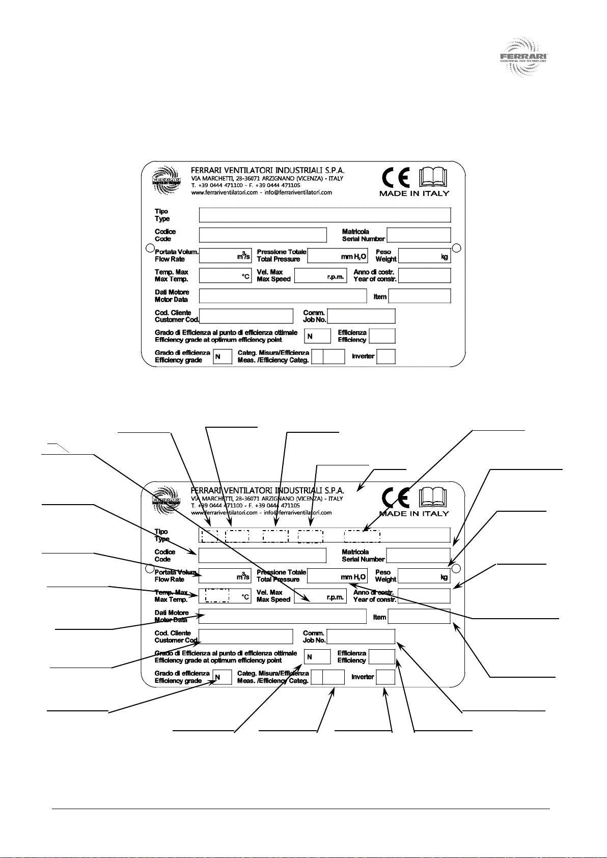
2.3 Fan identification
The identification plate is the only means of fan identification recognized by the manufacturer. It must not be
modified, and must not be removed or damaged. Fig. 2-3 shows the plate fitted to the fan.
Fig. 2-3 Identification plate of fan described by this manual
Fig. 2-4 Key to reading fan identification plate
Fan construction
year
2013
1310460
GR. 132 7,50 kW 4 POLI 50 Hz
EF0906I04AA02
EF 906/I 4A/A 132 A19
FVI customer
code (optional)
FVI customer order
number (optional)
FVI customer item
number (optional)
Type and
characteristics of
motor installed
Fan flow capacity
(optional)
Total fan pressure
(optional)
Serial number
Fan identification
code
Fan series
Fan size
Version/use/flow
Blade fitting
angle
60
Maximum temperature of
fluid moved in °C
Manual
Installed motor
size
Fan weight
Efficiency grade*
*In conformity with EU Regulation No. 327/2011
Efficiency grade at
optimum energy
efficiency point*
Efficiency
measurement
category*
Powered with
inverter*
Efficiency*
Maximum
rotational speed
14 of 120
MVA 02 rev 5 - December 2017
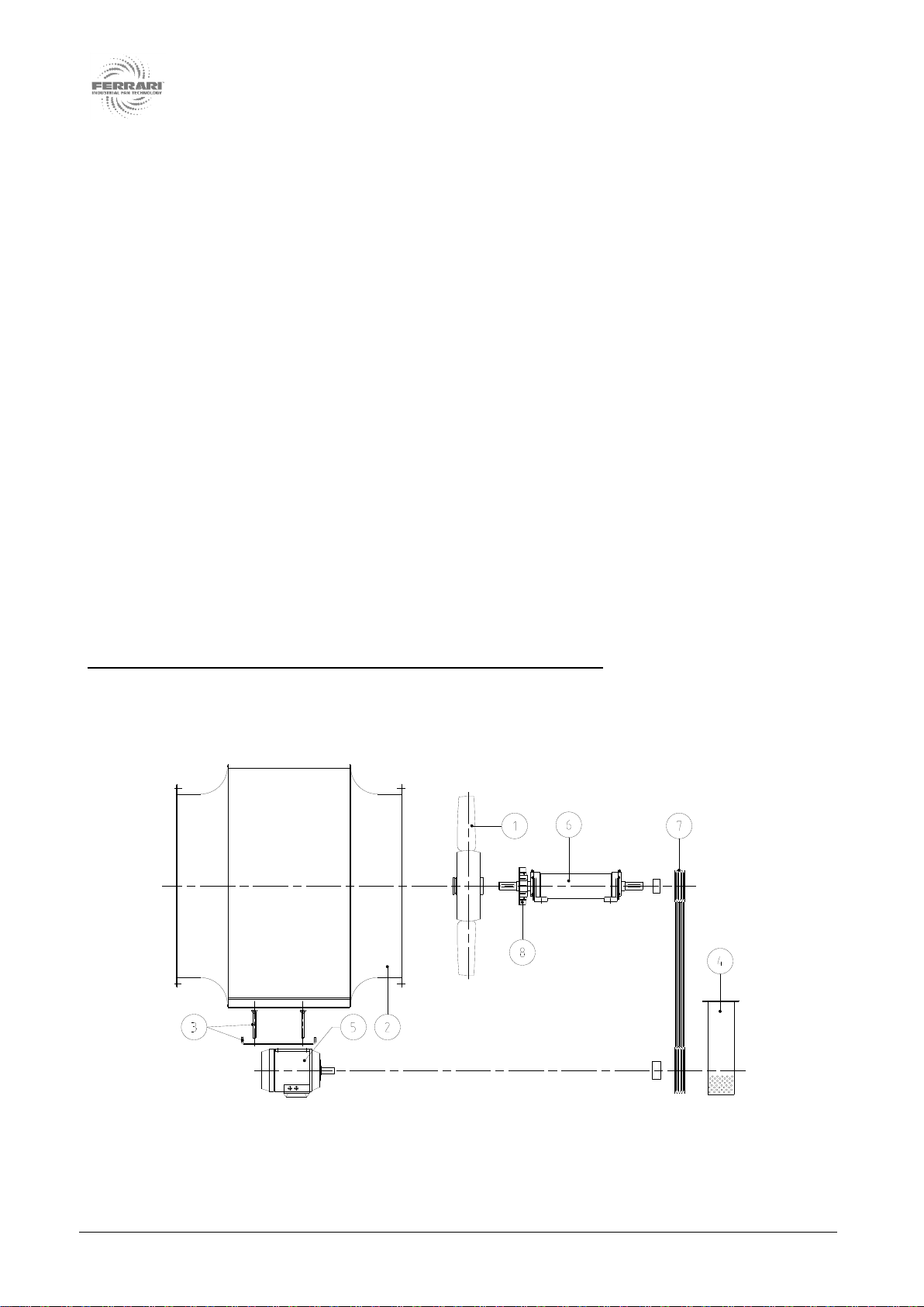
2.4 Description of fan
Taking the fan shown in Fig. 2-5 as an example, an axial fan is generally constituted by the following
components:
an impeller that rotates to impart the necessary energy to the fluid (1);
a casing housing the impeller, with a cylindrical shape (2);
a motor support base with respective stays (3);
guards to prevent accidental contact with all rotating parts (4);
The power that permits rotation of the impeller is provided therefore by a motor (5), usually but not
exclusively electrically driven, linked to the impeller directly or by other organs of transmission, such as for
example:
a support complete with bearings and drive shaft (6);
transmission by drive belts and trapezoidal pulleys (7) or flexible couplings to transfer the energy
provided by the motor;
a cooling fan between the impeller and the support, if the fluids are to be moved with an operating
temperature greater than 60°C (8)
For versions 8 and 12 (see Fig. 2-1) a common base is normally provided to support the fan, the motor and
the transmission.
Fans may be supplied with different construction characteristics that may also include other components not
indicated in the above descriptions and that must be defined for each specific case. Fans may also be fitted
with additional accessories (as shown on pages 187 to 204 of the “Axial Fan Catalogue”).
FVI fans are always supplied without control and monitoring systems.
Fig. 2-5 Example of version 9 with fan components indicated

MVA 02 rev 5 - December 2017
15 of 120
2.5 Envisaged use and foreseeable uses according to experience, and prohibited
uses
The envisaged use for the fan with the identification plate as shown in Fig. 2-3 is as follows:
An industrial axial fan is a machine that serves to move a gaseous fluid inside a fluid movement system to
which the fan is connected by means of ducts and technical chambers provided for this purpose. The flow of
the fluid moved by the machine enters and leaves the fan in an axial direction.
The energy required to move the volumes of fluid entering the system from the suction intake is transferred
by the rotation of the impeller inside the casing. Impeller rotation is obtained in most cases by the energy
supplied by an electric motor, as indicated earlier in paragraph 2.4 of this manual.
The fan must be used in the flow range specified in the performance diagrams. Use of the fan with flows
lower than the minimum value indicated in the diagrams may cause unstable fluid dynamic operation and
vibrations.
Axial fans are used in many application associated prevalently with the development of industrial processes.
Here is a list of some possible industrial sectors with application examples:
Food processing sector (drying, cooking, circulation)
Textile sector (air conditioning and treatment, drying)
Steel sector (extraction of fumes)
Brick products sector (extraction of fumes , drying)
Woodworking sector (filtration, dust removal)
Tobacco sector (conditioning, extraction of fumes)
Paper sector (air conditioning and treatment, drying)
Painting sector (filtration, dust removal)
Transport sector such as maritime and railways (conditioning, motor cooling)
Energy sector (turbine cooling, oil platform conditioning)
Other applications not listed but agreed with our Engineering and/or Research & Development Area.
Some categories of use other than those described above are excluded, and more specifically:
Operation of the fan with non-gaseous fluids or with fluids with characteristics different from those
defined in the technical information sheet accompanying the fan, since structural damage may be
caused to the fan with the possible risk of injury to persons and/or damage to things;
Operation of the fan in all types of system with pressures (present or even partially generated by the
fan) greater than 1.05 times standard atmospheric pressure, since structural damage may be caused
to the fan with the possible risk of injury to persons and/or damage to things;
Operation of the fan in all types of system classified in accordance with the ATEX 2014/34/EC
Directive and that move potentially explosive fluids, since risks of ignition/explosion may occur with
possible injury to persons and/or damage to things. Fans that are specifically constructed, classified
and marked for ATEX conformity for a suitable category for the installation location are excluded,
and these must be accompanied by the legally required documentation;
Operation of the fan in industrial chemical plants where the fluid moved is highly corrosive for the
materials used in fan construction, or in the presence of highly toxic fluids where the construction
methods of casings and the types of seal used are not suitable for this specific application, since
structural damage may be caused to the fan with the possible risk of injury to persons and/or
damage to things;
Operation of the fan in mining industry plants and with underground installations, since additional
risks not considered in the use of the fan above ground may arise, with possible injury to persons
and/or damage to things.

16 of 120
MVA 02 rev 5 - December 2017
2.6 Life cycle of fan
The reliability of all components is guaranteed by a production process with ISO 9001 certification and by
compliance with the programmed maintenance intervals indicated in paragraph 12.3 of this manual.
The components normally subject to wear are the following:
bearings, calculated for a theoretical duration normally of 40,000 hours
drive belts, calculated for a theoretical duration of 25,000 hours
For safety reasons, guards in electrowelded wire must be replaced every 2–3 years.
In the hypothesis of use of the fan at constant speed for two work shifts every day equivalent to 16 hours,
calculated for 250 days per year, the expected life cycle for the impeller is equivalent to 40,000 hours.
In case of use in conditions of particularly difficult operation (medium, high), this limit must be reduced. Any
such reduction must be assessed in collaboration with the FVI Technical Office. In the specific case of
operation at variable speeds, the impeller life cycle must be assessed on a case-by-case basis, and must
also be agreed with the FVI Technical Office.
CAUTION:
Do not exceed the maximum rotation speed indicated by FVI.
Do not use ON-OFF operating cycles unless expressly approved by FVI.
Do not use variable-speed cycles unless expressly approved by FVI.
Do not subject the fan to thermal gradients greater than 3°C/minute.
Even if it has never operated, an impeller that has been stored for more than ten years must be checked by
FVI for possible defects before it can be used.
MVA 02 rev 5 - December 2017
17 of 120
3 WARNINGS AND MAIN SAFETY INDICATIONS
3.1 Installation instructions: general information
Fans can be installed in four different ways, in conformity with the UNI EN ISO 13349
standard:
Type A: open intake and open exit;
Type B: open intake and exit connected to duct;
Type C: intake connected to duct and open exit;
Type D: intake and exit connected to ducts.
Generally, FVI does not and cannot know which of the above installation types will be chosen and
applied by the user, and unless otherwise specified by contract, the fan is supplied for installation
types B, C or D, according to the fan series and flow (for a complete overview of installation types
supplied see Chart 3-1). The person responsible for designing the system, together with the final
user, must conduct an analysis of risks for the specific installation type chosen.
Depending on the way that it is intended to install and insert the fan in the fluid movement system, the
following guards must be installed, according to installation type:
Type A installation: fixed FVI guards installed on intake and exit;
Type B installation: fixed FVI installed only on intake;
Type C installation: fixed FVI guard installed only on exit;
Type D installation: no fixed guards installed on intake and exit.
The system designer and the user must ensure that ducting systems are fitted with conformant guards for
the duct connections made, as follows:
Type A installation: no guards (no ducts are connected);
Type B installation: fixed guard fitted on exit duct;
Type C installation: fixed guard fitted on intake duct;
Type D installation: fixed guards fitted both on intake and exit ducts.
CAUTION:
Unless otherwise specified by contract, fans are supplied for installation types B, C or D in
conformity with the UNI EN ISO 13349 standard and according to fan series and flow. Consult
Chart 3-1.
Always verify all safety aspects of the installation type chosen.
CAUTION:
Unless otherwise specified by contract, the fan and guards are suitable for installation as a
single unit, and must not be subjected to effects of fluid dynamics caused by other machines
installed in the same fluid movement system.
18 of 120
MVA 02 rev 5 - December 2017
With regard to guards to be fitted to ducts, in compliance with the design project, they must prevent access
to parts of the fan and its accessories that could cause injuries. They must also be sufficiently robustly
constructed to resist the stresses generated by the machine and environmental conditions.
FVI invites users and/or system designers to design, construct and install guards in conformity with the
criteria of the UNI EN ISO 12499 standard.
CAUTION:
Even with guards installed (regardless of the conditions of supply or installation), the fan may
be dangerous due to the effects of indrawn or moved air.
Depending on the dimensions of the fan, this type of danger may even CAUSE DEATH.
The risk of being crushed against the intake grille may be fatal or may cause serious injuries
(crushing of body parts, unconsciousness).
CAUTION:
It is advisable to adopt precautions that prevent access to the room containing the fan while it
is operating, or to keep persons away with fixed guards that maintain a safe distance from the
intake opening.
For details consult the UNI EN ISO 13349 and UNI EN ISO 12499 standards.
WARNING:
Check the efficiency of all guards every month. In case of wear, damage or breakage, replace
them immediately.
Guards must be fixed securely in position using fixings that are not slackened by vibrations, and that require
the use of a tool for their removal.
CAUTION:
On starting and in compliance with programmed maintenance intervals, check that nuts and
bolts are correctly tightened. Monitor vibration levels with a vibrometer, and establish an alarm
threshold (see paragraph 12.3).
It is always the responsibility of the installer to guarantee that there is an adequate level of protection against
the risk of accidental contact with moving parts.
The installer and the user must also take other types of risk into consideration, and in particular those
deriving from the entry of foreign bodies and the intake of explosive, inflammable or toxic gases or gases at
a high temperature.
The risks involved in maintenance operations must also be taken into consideration. It must be possible to
perform these operations in conditions of maximum safety, by isolating the fan from the motor or by taking
other suitable precautions.
CAUTION:
A safety procedure for access to the fan must be compiled, taking into consideration the
indications provided by the manufacturer, information deriving from the analysis of risks at the
installation point and safety requirements in workplaces.
MVA 02 rev 5 - December 2017
19 of 120
3.2 Installation type A: Instructions for assembly, installation and connections
In case of type A installations, since neither the intake nor exit of the fan are connected to ducts, guards
must be fitted on both the intake and the exit.
Guard dimensions can be obtained from the dimensional drawing given in catalogues, from scale and non-
scale drawing programs downloadable from the reserved area of the website, or from any dimensional
drawings provided as documentation together with the products supplied.
CAUTION:
Guards are designed to protect against accidental contacts and to resist the pressures
generated only by the fan to which they are fitted.
Each guard, if supplied individually, can be used only on the fan for which it was designed. If
therefore a guard is ordered individually, it is compulsory to provide the reference details of the
fan to which it will be fitted (serial number).
Guards of the type shown in Chart 3-1 must be bolted to the fan intake and exit. Chart 3-1 also shows,
highlighted with a grey background, the guards that depending on the installation type supplied constitute
part of the fan itself.
Guard types are shown in Fig. 3.-1, Fig. 3-2, Fig. 3-3, Fig. 3-4, Fig. 3-5 and Fig. 3-6.
Fasteners for each type and size of guard are shown in Chart 3-2, and tightening torques in Chart 12-1.
Assembly diagrams for guards are shown in Fig. 3-7, Fig. 3-8, Fig. 3-9, Fig. 3-10, Fig. 3-11 and Fig. 3-12
respectively.
For flow definitions see Paragraph 2.1 Definitions, basic principles, terminology used and
correlated documents.
20 of 120
MVA 02 rev 5 - December 2017
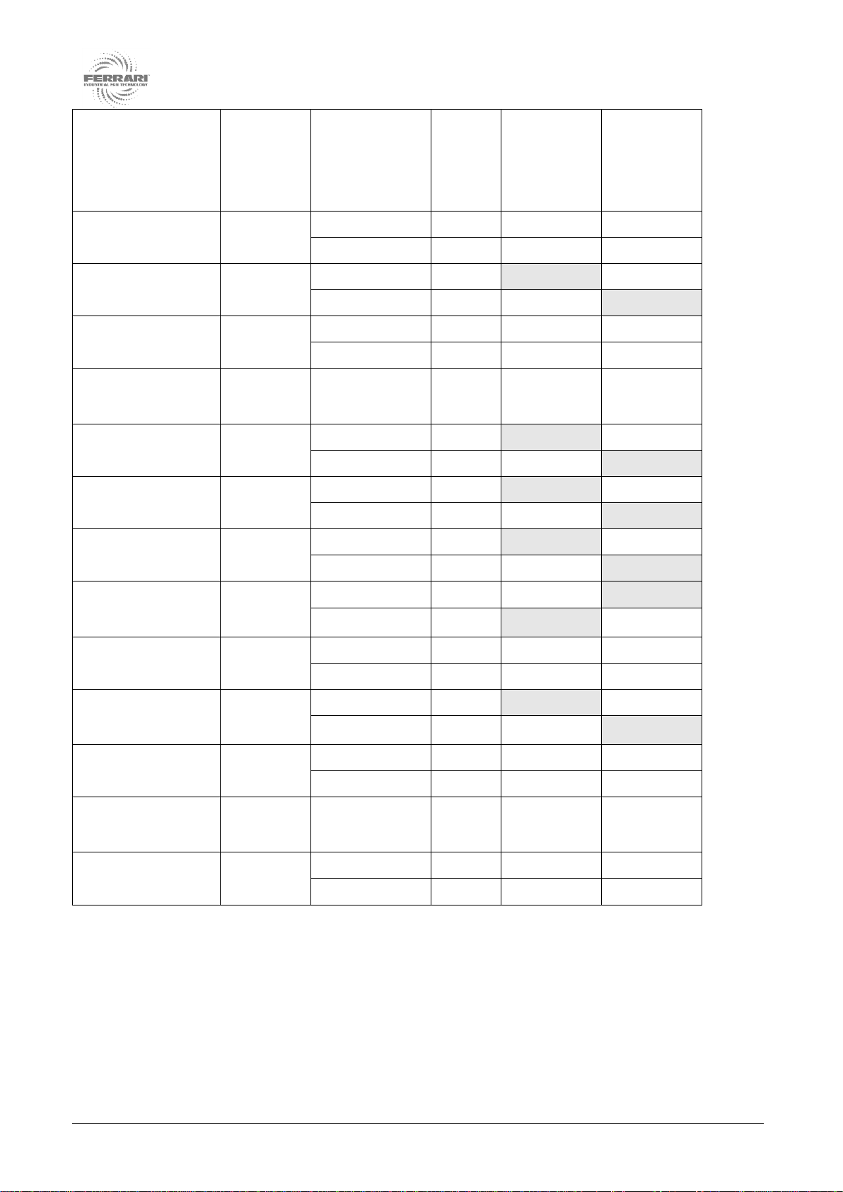
Series
Impeller
hub
material
Installation
type supplied
according to
UNI EN ISO
13349
Flow
Intake
guard
(mesh)
Exit guard
(mesh)
EF
aluminium
D
A
RC
RC
D
B
RC
RC
ES
aluminium
B
A
RG
RC
C
B
RC
RG
EB
aluminium
D
A
RC
RC
D
B
RC
RC
EFR
(version B)
aluminium
D
B
RC
RC
EK
aluminium
B
A
RE
RC
C
B
RC
RE
EQ
aluminium
B
A
RD
RC
C
B
RC
RD
EP
aluminium
B
A
RD
RC
C
B
RC
RD
ET
(version A)
aluminium
C
A
RG
RT
B
B
RT
RG
EF
steel
D
A
RC
RC
D
B
RC
RC
ES
(version A)
steel
B
A
RS
RC
C
B
RC
RS
EB
steel
D
A
RC
RC
D
B
RC
RC
EFR
(version B)
steel
D
B
RC
RC
AF
steel
D
A
RC
RC
D
B
RC
RC
Chart 3-1 Installation types supplied and mesh guards used
(grey backgrounds show guards that depending on the installation type supplied constitute part of the fan
itself)
This manual suits for next models
8
Table of contents
Popular Fan manuals by other brands


Greenheck
Greenheck Series L Installation, operation and maintenance manual

Vents
Vents Quiet-Disc user manual

Somogyi
Somogyi home HF 9/WH instruction manual

Kilargo
Kilargo IFD44-LL Series installation instructions

Casablanca
Casablanca Panama 59510 Owner's guide and installation manual

Objecto
Objecto FLOW F1 user manual


