Ferrofish A32 DANTE User manual

Manual
Professional 32 x 32-channel AD/DA Converter

Introduction
Thank you for choosing the A32 as your new A/D D/A converter!
The A32 is an A/D-D/A converter with 32 analog inputs and outputs,
64x64 MADI and 32x32 ADAT digital channels.
Furthermore, it is possible to route internally between all I/O channels
and even create submixes, which can be monitored using the
headphones output on the front of the A32.
Four TFT screens show all analog input and output levels at the same
time and allow perfect visualization of all the A32’s settings.
The intuitive one knob operation together with the integrated help
system makes using the A32 a breeze.
We’re sure that our A32 will become a valuable part of your studio.
Software and Updates
For more information concerning updates and support please visit our
website: www.ferrofish.com

Operation
1
A32 operation
The A32 can be fully controlled from the front panel by using the
SELECT wheel and the MENU button. The POWER button can be used
as a home button and for
switching the unit on and off. It is
also possible to control the A32
via USB, MIDI or MIDI-over-
MADI.
The main screen shows the levels of all 32 analog inputs and outputs as
well as other important status information, so that you always know
what is happening. You can always return to this screen with a short
press of the power button.
The status line beneath the meters shows the following (from left to
right):
The current synchronization source and sample frequency
Whether there is MIDI input from the MIDI plugs, from MIDI-
over-MADI and/or from USB
If power is attached to the left and/or right mains input
Any audio input present on optical MADI, coax MADI and/or
ADAT 1-4. The symbol will be yellow if only audio is received
and green if the input is also synchronous to the sample
frequency
If BNC wordclock input is present

Operation
2
Headphones
Turning the SELECT knob whilst the main screen is visible on the
display will make the headphones menu appear. You can now select
the volume of the headphones output:
By pressing the MENU key, you can also select and then change the
following:
Source: You can choose between ANALOG IN / OUT, MADI IN /
OUT, ADAT IN / OUT and MIX 1-7.
Channel: Once you have chosen a source you can then select
the specific channel(s) to be monitored. Cycling thru the
channels will let you first select mono channels, followed by
stereo channel pairs.
If you prefer to have a full mix of the channels, you can choose a mix
preset. For further information regarding mix presets please see the
MIX chapter.

Operation
3
main menu
Pressing the MENU key shows the main menu. Use the SELECT wheel
to choose the desired menu option and press MENU to activate it.
The main menu has the following functions:
CLOCK
Here you can set the A32 to generate the wordclock itself (master) or
listen to a wordclock signal (slave) from an external source. If choosing
Master you can also select the sample rate here.
MIX
You can select, load and edit one of seven mixer presets in this menu.
The preset mixes can be monitored using the headphones output.
DIGITAL
In this menu you can see the analog I/O’s as meters and all digital I/O’s
as LED dots with a traffic light color scheme. This means that every dot
shows a digital channel, which changes color according to the level of
the signal. For further information, please see the DIGITAL chapter.
SETUP
Setup lets you change the gain-levels of the analog inputs and outputs.
Additionally, you can define the routing of the A32, set the MIDI and
MADI processing, change global settings or lock the front panel.
DSP
In the DSP menu optional DSP plugins can be loaded and edited.

Operation
4
PRESET
Levels, gains and the routing of the A32 can be saved and loaded in up
to six different preset slots.
HELP
You can change the language of the help system here, get information
about the schematic structure and lookup the firmware version of the
A32.
Operation
5
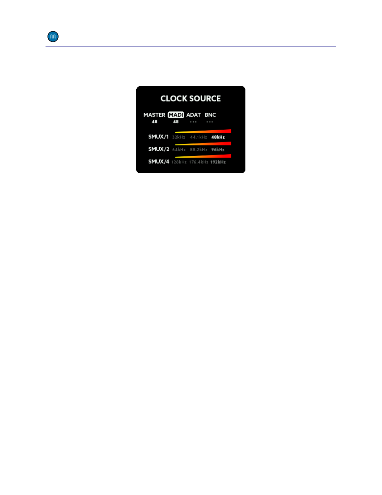
main menu –CLOCK
The CLOCK SOURCE menu lets you select the wordclock source and the
sample frequency of the A32 when running in Master Mode:
The numbers below the labels show the internally generated clock as
Master or the measured external sample rate. If no sample rate is
detected, „---“will be displayed.
MASTER
By selecting MASTER as the clock source, the internal clock generator
will be used for the wordclock. This circuit consists of a high precision
temperature compensated oscillator, which can be set to the desired
frequency.
MADI, ADAT
If you set the clock source to MADI or ADAT, the A32 extracts the
wordclock signal from these digital inputs, reduces jitter using the
digital PLL circuit and routes it back to the BNC output. The A32 then
uses this clock signal. When using higher sample frequencies, the MADI
and ADAT interfaces employ SMUX modes, in this case you will need to
set the desired SMUX frequency manually. Please see the SMUX
chapter for more details.
BNC
When receiving an external wordclock via the BNC IN of the A32, the
wordclock signal will also be routed thru the jitter reduction stage
before using it.

Operation
6
SMUX operation
Internally the A32 always uses all 32 analog channels, but the number
of digital MADI and ADAT channels is limited in relation to the SMUX
mode currently in use.
SMUX/1
SMUX/1 offers frequencies from 32kHz up to 48kHz.
SMUX/2
When using higher frequencies (64kHz to 96kHz) SMUX/2 is used. This
means that a single channel of audio is split across two consecutive
channels of the digital stream when transmitted via ADAT or MADI
(signal multiplexing). Consequently, the number of ADAT or MADI
channels is halved. For example, when using a sample rate of 96kHz
there will be 32 channels available via MADI as opposed to the usual
64 channels at 48kHz and below. Likewise, at 96kHz each ADAT cable
will carry 4 channels as opposed to 8 at 48kHz and below.
SMUX/1 and SMUX/2 offer redundant MADI. This means, that when
the MADI signal is lost, the A32 automatically switches to the other
MADI input.
SMUX/4
The SMUX/4 operation (128kHz-192kHz) divides the information of
each channel across four channels. This reduces the bandwidth of the
digital channels by a factor of 4. ADAT is not supported at that speed
and is switched off. The MADI cable only offers 16 channels at
SMUX/4. In order to still be capable of transferring all 32 analog
channels a special SMUX/4 mode will be activated. This mode uses
both MADI coax and optical connections simultaneously to transfer all
32 channels:
optical MADI: transmits and receives analog channels 1-16
coax MADI: transmits and receives analog channels 17-32
Operation
7
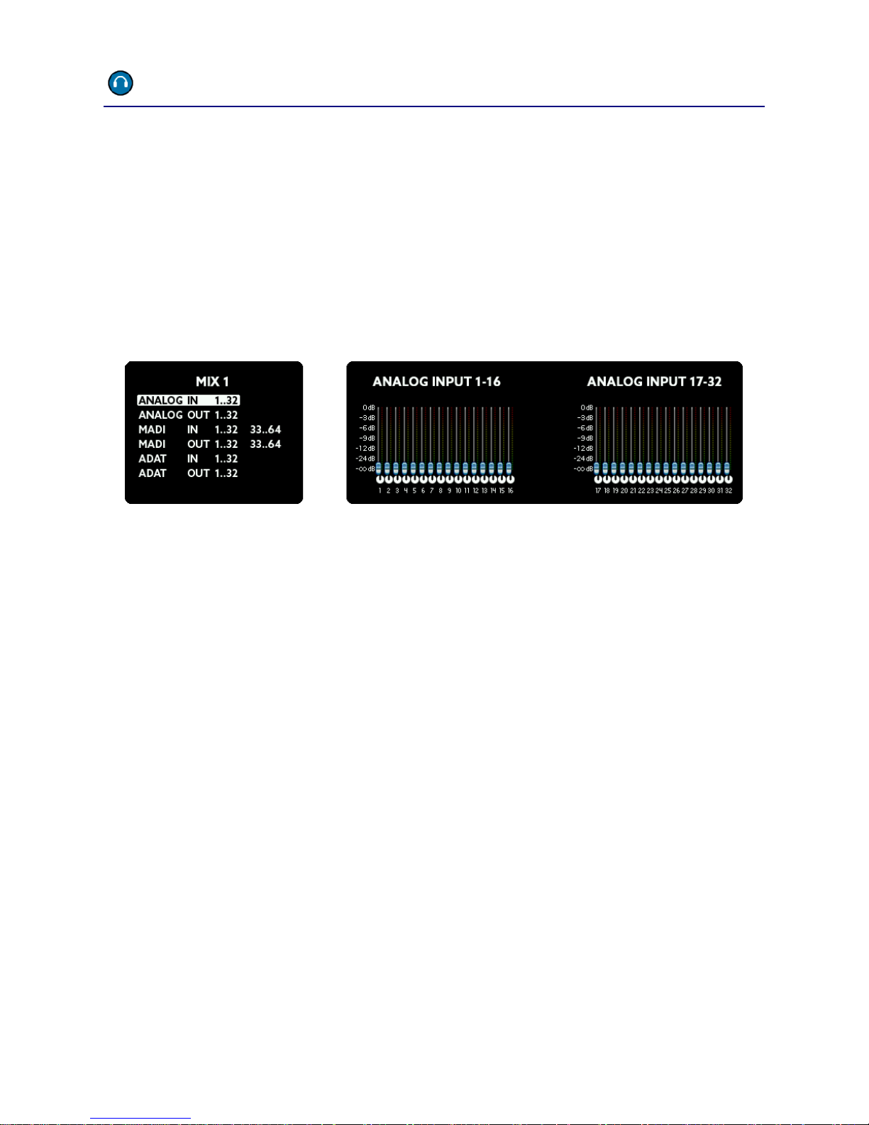
main menu –MIX
Inside the MIX menu you can select one of seven mix presets. The A32
allows you to create a custom mix of all analog and digital I/O’s which
can then be sent to the stereo headphones output on the front panel.
You can choose between these mix presets within the headphones
screen by selecting MIX 1 to 7 as the source.
In the MIX screen, after selecting the number of the MIX preset, press
MENU to edit:
First, select one of the eight groups. The actual mix of channels from
within this group will now be visible on the right screens. Press the
MENU button to edit the mix in three steps:
Select the channels: Scroll to select either a single channel or
group of multiple channels (2, 4, or 8). Continue by pressing
MENU.
Now you can adjust the level. When it is set as desired, press
MENU again.
Finally set the pan. If you selected two or more channels, the
even numbered pan knobs move in the opposite direction to
the rotation of the SELECT wheel.
These steps you can repeat as desired. When finished, hold down
the MENU button for a few seconds. All changes will be stored and
won’t get lost even when switching the unit off and on.

Operation
8
main menu –DIGITAL
The DIGITAL menu shows all analog and digital inputs and outputs. All
digital inputs and outputs are shown as dots with a traffic light color
code.
In this way, you have an overview of all channels at a glance.
The traffic light LED colors have the following meaning:
Hold down the MENU button for a few seconds to get back to the
previous screen.
Color
Range
red
-3dBFS to 0dBFS
yellow
-15dBFS to -4dBFS
green
-59dBFS to -16dBFS
grey
-inf to -60dBFS
Operation
9
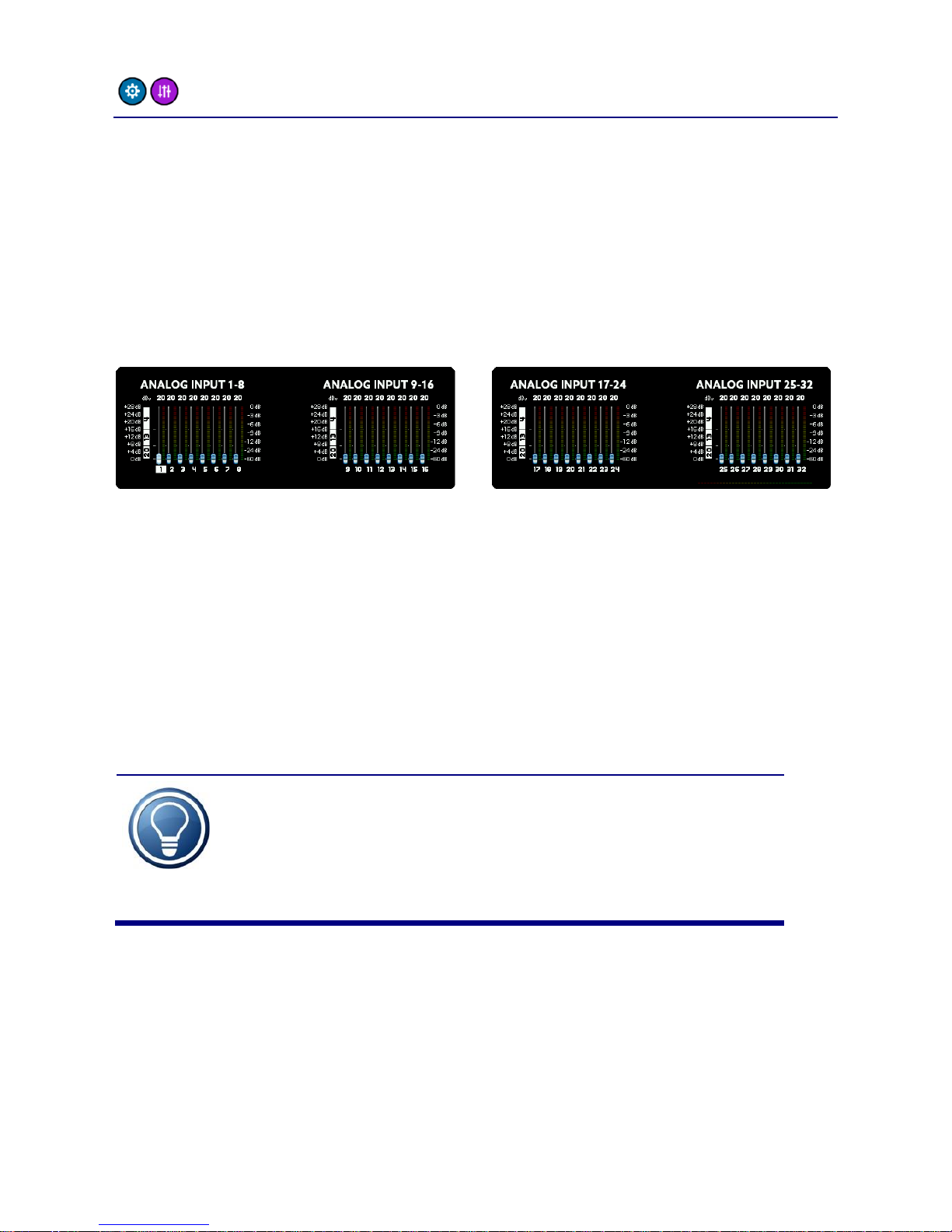
main menu –SETUP -> GAINS
The analog inputs of the A32 can be set to different sensitivities. You
can choose between three reference levels: +4dBu, +13dBu and
+20dBu. Using the DSP, you can additionally set the reference levels
from -8dBu to +20dBu in 1 dB steps. The DSP always calculates the
optimum configuration. For example, if you set +12dBu, the analog
reference will be set to +13dBu and the signal will be amplified by 1dB,
because it is only 12dBu.
The number on top of the fader shows the maximum dBu level, which
the input is able to handle. When the fader is set to 20, as in the
picture above, the input can handle a maximum input level of +20dBu.
Avoid exceeding this maximum level to prevent digital clipping.
In addition, you can see the levels of the analog inputs and so easily set
the correct gain. The dB scale of these levels is found on the right hand
side of the screens.
The minimum value -8dBu corresponds
(approximately) to the reference level of -10dBV used
by consumer devices, like CD-players for example.
Operation
10
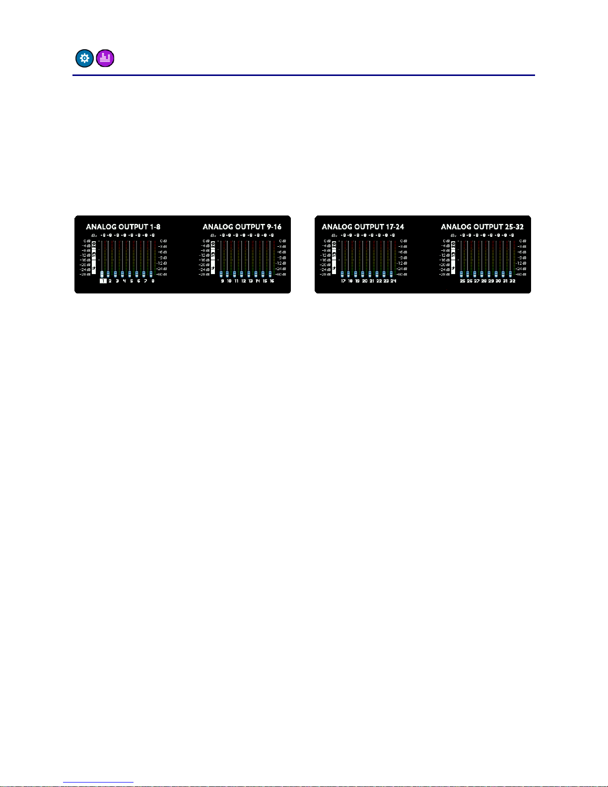
main menu –SETUP -> LEVELS
The LEVELS screen is similar to the GAINS screen described on the
previous page and is responsible for the levels of the analog outputs.
As with the inputs, you can set the level of each channel in 1dB steps
from -8dBu to +20dBu. The A32 offers individual analog level switching
of +4dBu, +13dBu and +20dBu. This means that this level is reached
when the digital output reaches 0dBFS.
If you select one of the three reference levels exactly, the digital signal
will be converted 1:1 to analog. However, if you select a value in
between these reference levels, the DSP will calculate the optimal
combination between analog and digital levelling. For example, if you
select +12dBu the analog output will be switched to +13dBu and the
digital signal will be attenuated by 1dB to reach the +12dBu output
level.
Just like the inputs you can also meter the levels of the channels here.
Please note, the level of the outputs will not change when adjusting
the amplification here, because you see the digital level before digital
and analog amplification.
Operation
11
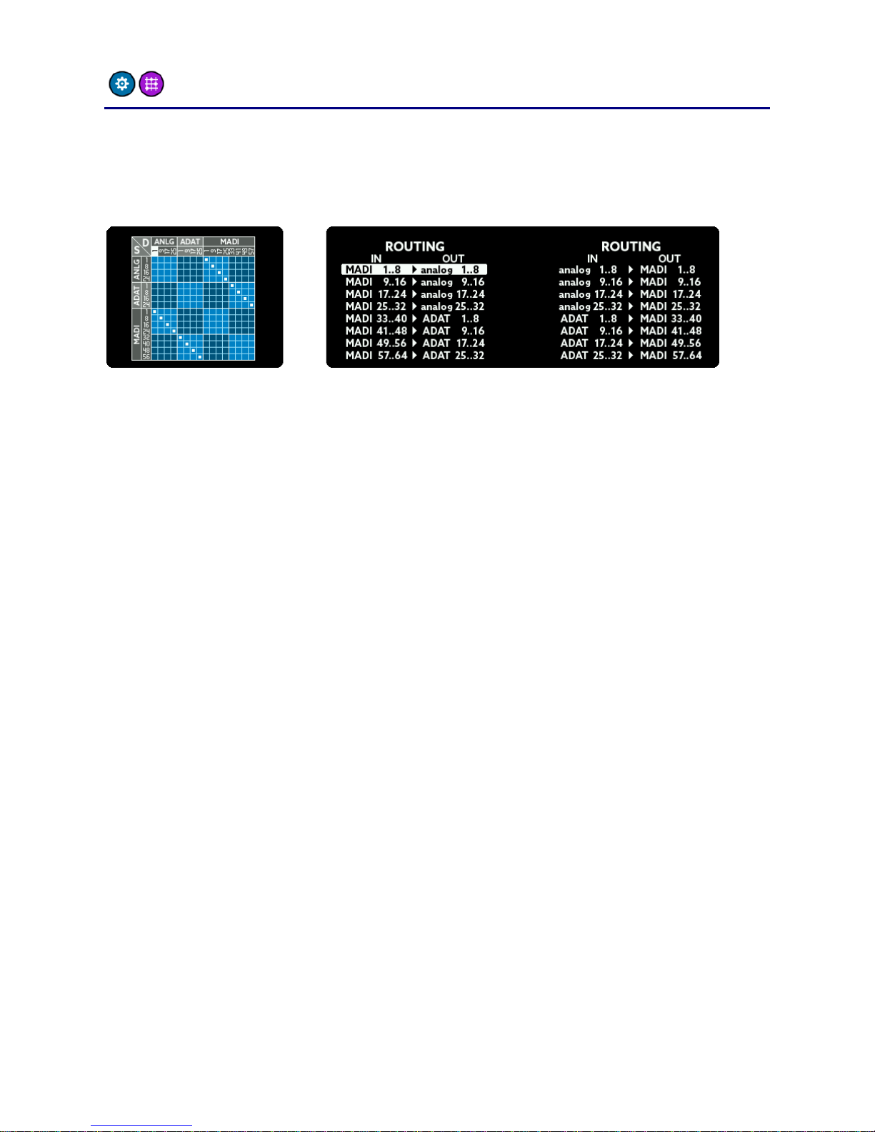
main menu –SETUP -> ROUTING
The A32 features a sophisticated routing matrix. In the ROUTING
screen you can see a graphical representation on the left side and a list
view on the right screen.
To change the routing, do the following:
Choose the output: Turn the SELECT rotary to highlight a block
of 8 outputs. It corresponds to a column on the graphical view
and a line on the list view.
Choose the input: Press MENU. You will now be able to connect
an input to the chosen output by turning the SELECT rotary. The
inputs are shown as rows in the graphical view or as text on the
left hand side of the list view line.
Hold down the MENU button for a few seconds to leave the routing
screen.

Operation
12
main menu –SETUP -> MADI
The A32 has two MADI formats (one optical and one coaxial) which can
be used in a very flexible way:
1 - optical
The A32 only uses the optical MADI
input. No automatic switching between
the formats will happen.
2 - optical
The A32 uses the optical MADI input.
When the signal is lost, the A32 switches
to coax MADI. It will only switch back to
optical if the coax signal is subsequently
removed.
3 - optical
Same function as 2. In addition, both
inputs are scanned constantly and if no
signal is present on one a warning will be
shown on the main screen.
4 –coax
The A32 only uses the coax MADI input.
No automatic switching between the
formats will happen.
5 –coax
The A32 uses the coax MADI input.
When the signal is lost, the A32 switches
to optical MADI. It will only switch back
to coax if the optical signal is
subsequently removed.
6 –coax
Same function as 5. In addition, both
inputs are scanned constantly and if no
signal is present on one a warning will be
shown on the main screen.
Operation
13
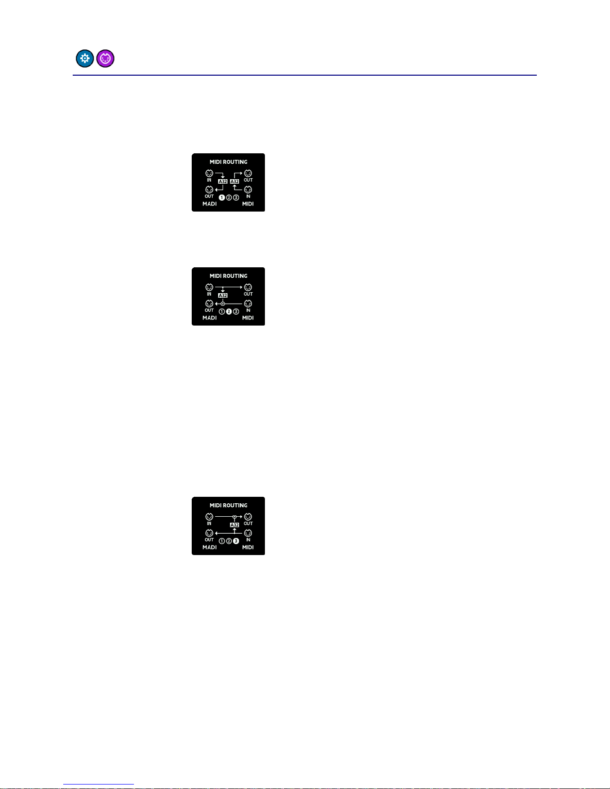
main menu –SETUP -> MIDI
The MIDI routing screen is intended to allow you to choose the way
MIDI data is routed between MIDI and MIDI over MADI:
1 - separate
MIDI-over-MADI and MIDI are separated.
Control messages for the A32 are
scanned from both input ports and
replies are sent back to the
corresponding output port.
2 –MADI
priority
MIDI-over-MADI and MIDI are
connected: Data from the MIDI-over-
MADI port is sent to MIDI, and MIDI
input is sent back to MIDI-over-MADI.
The A32 receives and sends control
messages from/to the MIDI-over-MADI
port.
This way you can convert between MIDI-
over-MADI and MIDI while the A32
listens to the MIDI-over-MADI port.
3 –MIDI
priority
MIDI-over-MADI and MIDI are
connected: Data from the MIDI-over-
MADI port is sent to MIDI, and MIDI
input is sent back to MIDI-over-MADI.
The A32 receives and sends control
messages from/to the MIDI port.
This way you can convert between MIDI-
over-MADI and MIDI while the A32
listens to the MIDI port.
Operation
14
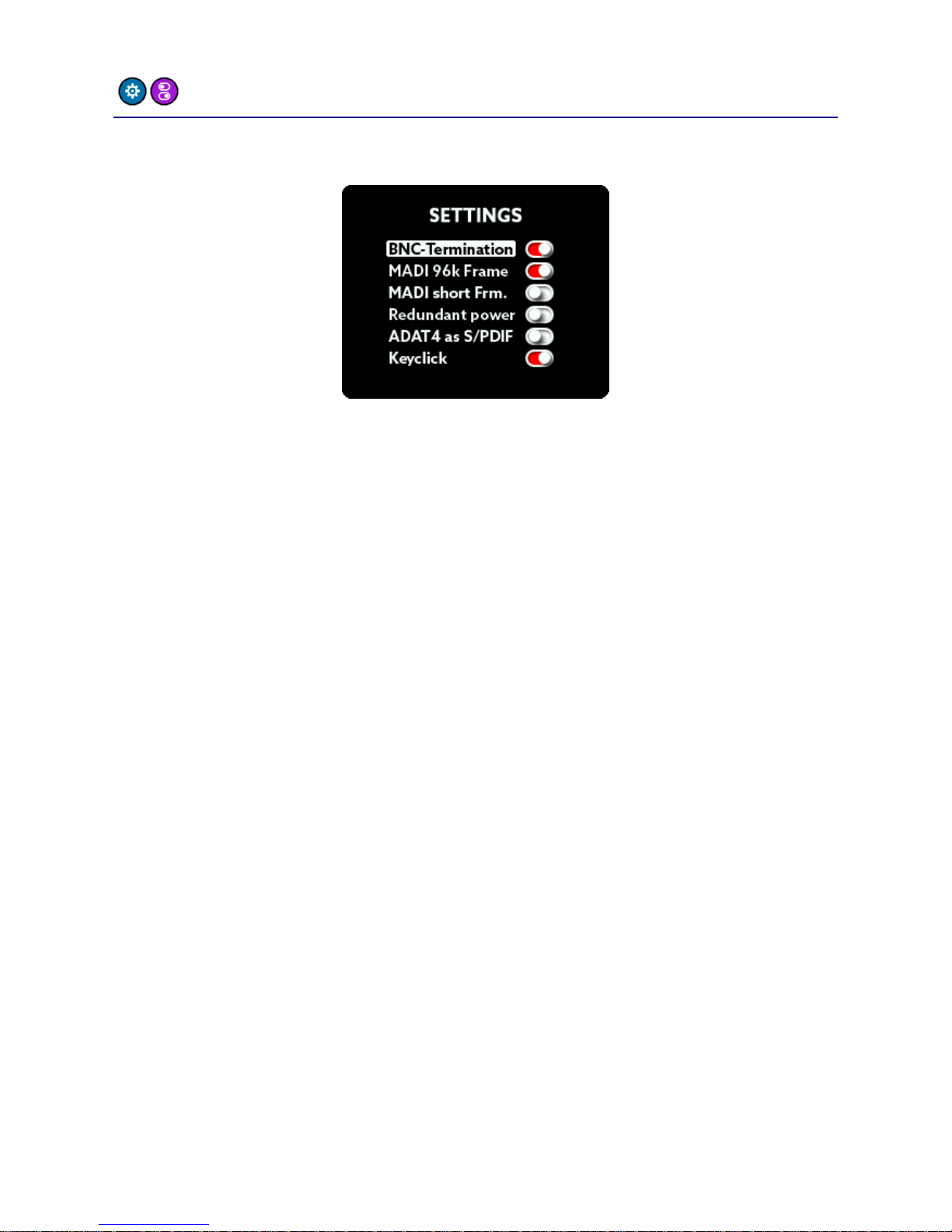
main menu –SETUP -> SETTINGS
In the SETTINGS screen you can switch some global features:
BNC Termination
The wordclock of the A32 is terminated internally with a 75-ohm
resistor by default. When daisy chaining wordclock of several units,
you should leave this option set to ON. If you’re using T-connectors for
the connections set this option to OFF, because in this case only the
last unit in the chain should be terminated.
MADI 96k Frame
There are two MADI transfer standards for the SMUX/2 mode (64kHz –
96kHz):
48k Frame: Identical to SMUX/1. The signal of 1 channel is split
(multiplexed) across a pair of 2 channels in order to double the
bandwidth. The usual 64 MADI channels are therefore reduced
to 32 channels.
96k Frame: The MADI stream is natively reduced to 32 channels
by increasing the frame size and allowing channels to be
transmitted directly.
Both formats transfer the same number of channels (32). The
advantage of the 96k frame mode is that the receiver can distinguish
between SMUX/1 and SMUX/2 mode automatically and can switch
appropriately. Please ensure both units have the same setting.

Operation
15
MADI short frame
Using the full bandwidth of MADI you can transfer 64 (SMUX/2: 32,
SMUX/4: 16) channels. By setting MADI short frame, the A32 will only
transfer 56 (SMUX/2: 28, SMUX/4: 14) channels. This setting
corresponds to an early MADI specification, which is capable of using
the remaining bandwidth for varispeed. Nowadays varispeed is not
commonly used in favor of having the full 64 channels.
Redundant Power
When using two power supplies for redundancy reasons, please set
this menu option to ON. If switched on, the A32 monitors both PSU
inputs. In case of a failure of one power supply, the A32 will display a
warning message on the main screen.
ADAT 4 as S/PDIF
The fourth ADAT I/O port can be configured as a stereo S/PDIF port. If
the sample rate of the connected device differs from the sample rate
of the A32, the external sample rate will be converted to that of the
A32 using a sample rate converter (SRC). The stereo S/PDIF input will
be distributed on the ADAT 4 channels, the stereo output is sourced by
the first two ADAT 4 channels.
Keyclick
This setting switches the key click sound on or off.

Operation
16
main menu –SETUP -> LOCK
To prevent accidental or forbidden operation of the A32, you can lock
the front panel. The headphone screen is still accessible, but all other
functions are locked. To lock the A32 front panel, enter the PIN
number printed on the bottom of the unit:
After entering the correct number, hold down the MENU button for a
few seconds to activate the lock.
To unlock the A32, repeat the procedure: Enter the correct number
and hold down the MENU button for a few seconds.
The PIN number of each A32 is fixed and can’t be changed by the user.
IMPORTANT: Keep the PIN code in a safe place!
Reconstruction of a PIN code by the manufacturer is
subject to a fee.

Operation
17
main menu –DSP
The Sharc DSP built into the A32 is used for routing, mixing and
gain/level settings.
But the DSP can do much more audio processing:
Using the USB connection, you can install Ferrofish-DSP plugins, which
are able to process audio effects with high accuracy and without
latency.
You can find more information on our website: www.ferrofish.com
Remark: You can’t use plugins from other manufacturers, esp. VST and
Scope plugins.
Operation
18
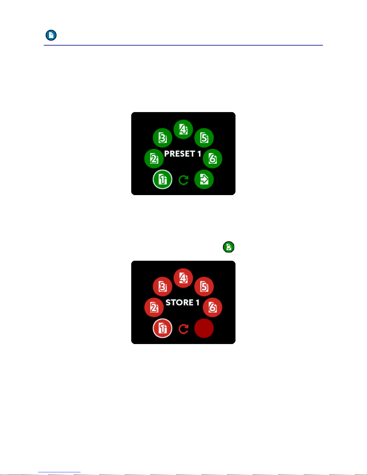
main menu –PRESET
The A32’s GAINS, LEVELS and the routing can be permanently stored in
one of six preset slots. This lets you pre configure the A32 and saves
you time later by just recalling the presets.
The PRESET Menu lets you choose which preset to load:
After selecting the number of the preset to load, you can choose which
parts of the preset you want to load: Gains of the analog inputs and/or
levels of the analog outputs and/or routing.
To store a preset, please use the store option :
Here you can store the settings using one of the six preset slots.
Other manuals for A32 DANTE
1
Table of contents
Other Ferrofish Media Converter manuals

Ferrofish
Ferrofish A16 AE User manual

Ferrofish
Ferrofish Verto 32 User manual

Ferrofish
Ferrofish PULSE16 DX User manual

Ferrofish
Ferrofish A32pro User manual

Ferrofish
Ferrofish PULSE 16 User manual

Ferrofish
Ferrofish Verto 32 User manual

Ferrofish
Ferrofish A16 MK-II User manual

Ferrofish
Ferrofish A32 DANTE User manual


