Siko WV5800M User manual

170/20
WV5800M/WH5800M
Absolute encoder with CANopen interface
User manual

WV5800M/WH5800M Date: 29.07.2020 Art. No. 90107 Mod. status 170/20 Page 2 of 63
Table of contents
1General Information .................................................................................................. 5
1.1 Documentation ........................................................................................................5
1.2 Definitions ..............................................................................................................5
2Intended use............................................................................................................. 5
2.1 Switching on the supply voltage.................................................................................6
3LED-signal................................................................................................................. 6
4Functional description ............................................................................................... 8
4.1 Measuring range.......................................................................................................8
4.2 Calibration ..............................................................................................................8
4.3 Reset to factory settings ...........................................................................................9
5Communication via CAN bus (CANopen) ...................................................................... 9
5.1 Telegram structure....................................................................................................9
5.2 Node control..........................................................................................................11
5.2.1 Network management (NMT) services .....................................................................11
5.2.1.1 NMT communication states ...............................................................................11
5.2.1.2 Toggling between the NMT communication states ................................................12
5.2.2 Boot-Up.............................................................................................................12
5.2.3 SYNC object........................................................................................................12
5.3 Process data exchange ............................................................................................13
5.3.1 Transfer of process data objects (PDO) ...................................................................13
5.3.1.1 Transmit-PDO (from the WV5800M / WH5800M to the master)................................13
5.4 Parameter data exchange.........................................................................................14
5.4.1 Transmission of Service Data Objects (SDO).............................................................14
5.4.1.1 Expedited Request/Response .............................................................................14
5.4.1.2 Normal Request/Response.................................................................................15
5.4.1.3 Error Response in SDO exchange ........................................................................16
5.4.1.4 SDO examples .................................................................................................17
5.5 Node monitoring ....................................................................................................19
5.5.1 Emergency service (EMCY) ....................................................................................19
5.5.2 Node Guarding....................................................................................................20
5.5.3 Heartbeat ..........................................................................................................20
5.6 Layer Setting Service (LSS) ......................................................................................21
5.6.1 State change ......................................................................................................22
5.6.1.1 Switch states of all LSS devices (Switch state global) ...........................................22
5.6.1.2 Switch states of individual LSS devices (Switch state selective)..............................22
5.6.2 Configuration .....................................................................................................23
5.6.2.1 Setting the Node ID (Configure Node ID) ............................................................23
5.6.2.2 Configuration of the baud rate (Configure bit timing parameters)...........................24
5.6.2.3 Activate baud rate (Activate bit timing parameters) .............................................25
5.6.2.4 Store configuration..........................................................................................25

WV5800M/WH5800M Date: 29.07.2020 Art. No. 90107 Mod. status 170/20 Page 3 of 63
5.6.3 Requesting parameters.........................................................................................26
5.6.3.1 Request Vendor ID ...........................................................................................26
5.6.3.2 Request Product Code.......................................................................................26
5.6.3.3 Request revision number...................................................................................27
5.6.3.4 Request serial number ......................................................................................27
5.6.3.5 Request Node ID..............................................................................................27
5.7 Directory of objects ................................................................................................28
5.7.1 Overview of objects .............................................................................................28
5.7.2 Object Description...............................................................................................30
5.7.2.1 1000h: Device Type..........................................................................................30
5.7.2.2 1001h: Error Register .......................................................................................31
5.7.2.3 1002h: Manufacturer Status Register ..................................................................31
5.7.2.4 1003h: Pre-defined Error Field...........................................................................31
5.7.2.5 1005h: COB ID SYNC message ............................................................................32
5.7.2.6 1008h: Manufacturer Device Name .....................................................................33
5.7.2.7 1009h: Manufacturer Hardware Version ...............................................................33
5.7.2.8 100Ah: Manufacturer Software Version................................................................33
5.7.2.9 100Ch: Guard Time...........................................................................................34
5.7.2.10 100Dh: Life Time Factor....................................................................................34
5.7.2.11 1010h: Store Parameter....................................................................................34
5.7.2.12 1011h: Restore Parameter.................................................................................36
5.7.2.13 1014h: COB ID Emergency message ....................................................................39
5.7.2.14 1017h: Producer Heartbeat Time........................................................................39
5.7.2.15 1018h: Identity Object.....................................................................................39
5.7.2.16 1200h: Server SDO Parameter ............................................................................41
5.7.2.17 1800h: 1. Transmit PDO Parameter .....................................................................41
5.7.2.18 1801h: 2. Transmit PDO Parameter .....................................................................43
5.7.2.19 1A00h: 1. Transmit PDO Mapping Parameter ........................................................44
5.7.2.20 1A01h: 2. Transmit PDO Mapping Parameter ........................................................45
5.7.2.21 2001h: Application offset .................................................................................46
5.7.2.22 2002h: Calibrate encoder value..........................................................................46
5.7.2.23 2003h: Limit speed low ....................................................................................46
5.7.2.24 2004h: Limit speed High ..................................................................................47
5.7.2.25 5000h: Diagnosis CAN Bus error.........................................................................47
5.7.2.26 5F0Ah: Node ID and baud rate Bus CAN ..............................................................47
5.7.2.27 6000h: Operating Parameters ............................................................................48
5.7.2.28 6001h: Measurement steps per revolution (Display per revolution = APU) ................49
5.7.2.29 6002h: Overall number of measurement steps ......................................................49
5.7.2.30 6003h: Preset value (calibration value)...............................................................50
5.7.2.31 6004h: Position value ......................................................................................50
5.7.2.32 600Ch: Absolute accuracy .................................................................................50
5.7.2.33 6030h: Velocity value.......................................................................................51
5.7.2.34 6031h: Speed parameters..................................................................................51
5.7.2.35 6200h: Cycle timer...........................................................................................53

WV5800M/WH5800M Date: 29.07.2020 Art. No. 90107 Mod. status 170/20 Page 4 of 63
5.7.2.36 6400h: Operating range (Area state register).......................................................53
5.7.2.37 6401h: Work Area Low Limit..............................................................................54
5.7.2.38 6402h: Work Area High Limit ............................................................................55
5.7.2.39 6500h: Operating Status...................................................................................56
5.7.2.40 6501h: Singleturn resolution.............................................................................56
5.7.2.41 6502h: Number of distinguishable revolutions .....................................................57
5.7.2.42 6503h: Alarms.................................................................................................57
5.7.2.43 6504h: Supported Alarms..................................................................................58
5.7.2.44 6505h: Warnings .............................................................................................58
5.7.2.45 6506h: Supported Warnings ..............................................................................59
5.7.2.46 6507h: Profile and Software Version...................................................................59
5.7.2.47 6508h: Operating Time.....................................................................................59
5.7.2.48 6509h: Offset value .........................................................................................60
5.7.2.49 650Ah: Module Identification............................................................................60
5.7.2.50 650Bh: Serial number.......................................................................................61
5.7.2.51 650Dh: Absolute accuracy.................................................................................61
5.7.2.52 650Eh: Device functionality ..............................................................................62

General Information
WV5800M/WH5800M Date: 29.07.2020 Art. No. 90107 Mod. status 170/20 Page 5 of 63
1General Information
1.1 Documentation
The following documents are associated with this document:
The data sheet describes the technical data, the dimensions, the pin assignment, the
accessories and the order key.
The installation instructions describe the mechanical and electrical installation with all
safety-relevant conditions and the associated technical specifications.
The User manual for actuator commissioning and integration into a fieldbus system.
EDS file (electronic data sheet); this file enables integration and configuration in a
CANopen network by means of commercial CANopen configurators.
You can also download these documents at http://www.siko-global.com/p/wv5800m and
http://www.siko-global.com/p/wh5800m.
1.2 Definitions
Decimal values are given as numbers without addition (e. g. 1234), except when indicated in
direct connection with binary or hexadecimal values, In which case the extension "d" will be
used (e. g. 1234d). Binary values are identified by adding "b" (e. g. 1011b) to the figures
whereas hexadecimal values are extended by "h" (e. g. 280h).
2Intended use
The WV5800M / WH5800M records the absolute travel information. The encoder can be
parameterized and read out via the CAN interface using the CANopen protocol.
For diagnostic purposes there are 3 LEDs in the encoder (yellow, red, green), which indicate
error or status information for diagnostic purposes.

LED-signal
WV5800M/WH5800M Date: 29.07.2020 Art. No. 90107 Mod. status 170/20 Page 6 of 63
Sensor Sensor
Controller / Encoder
CAN Transceiver
EMC-Filter
Voltage Monotoring
CAN+ CAN- CAN-GND +UB -UB
ST MT1
N S N S
Sensor
MT2
N S
Sensor
MT3
N S
Fig. 1: Block diagram
2.1 Switching on the supply voltage
WV5800M / WH5800M initializes after being switched on. During initialization, the LEDs light
up one after the other and the configuration parameters are loaded from the non-volatile
memory to the random memory of the controller.
The sensor will work with its default values as long as no changes have been made to it. With
parameters changed, the sensor will work with the changed data, which must be stored if they
are intended to be used after power off/on.
After completing the initialization procedure, the encoder send a specific NMT command, the
boot-up message, which informs the system about their availability. The WV5800M /
WH5800M is now in the pre-operational mode. In this state, the encoder can be parameterized
via SDO commands in accordance with the requirements of the application. This applies to
configuration parameters of the sensor unit as well as to the way it makes available to the
system its position values (asynchronous or synchronous data transmission).
3LED-signal
The encoder has 3 LEDs in the colors yellow, green and red for diagnosis and status purposes.
A yellow LED for device-specific states
A green LED for indicating the NMT status or the LSS configuration status (CAN Run LED)
A red LED for CAN error states or for indicating the LSS configuration status (CAN Err LED)
The LSS waiting status is not indicated via the LEDs.

LED-signal
WV5800M/WH5800M Date: 29.07.2020 Art. No. 90107 Mod. status 170/20 Page 7 of 63
Fig. 2: LED-signal
Device-specific diagnosis:
Error status
LED status
Maximum speed exceeded
On
Encoder is in the valid speed range
Off
Table 1: Device-specific status LED
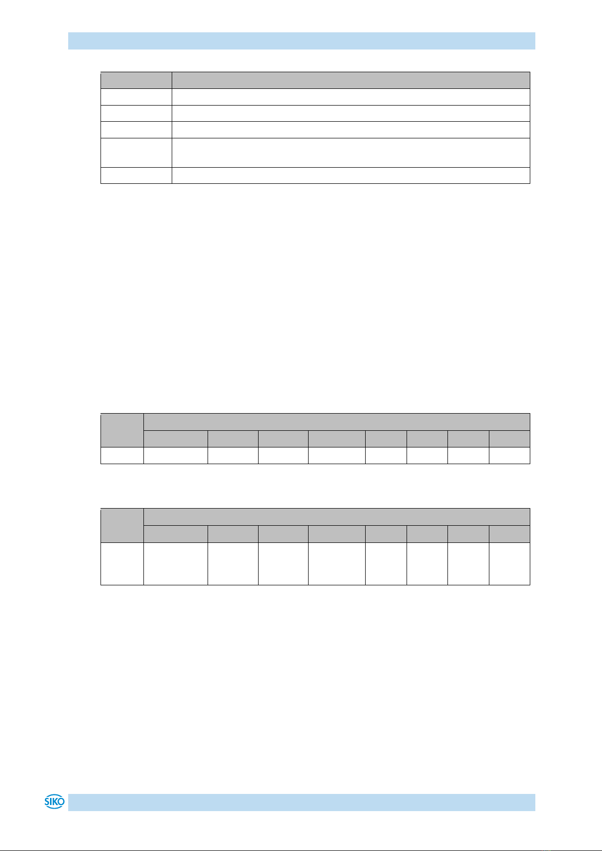
CAN diagnosis:
The CiA 303 Part 3 V1.4.0 indicator specification is the basis of the CAN diagnosis.
LED status
Description
On
LED is permanently on
Off
LED is permanently off
Flickering
Both LEDs alternately with the frequency of 10 Hz (50 ms on/off)
Flashing
LED flashes at a frequency of 2.5 Hz (200 ms on/off)
Single Flash
LED is 200 ms on, 1000 ms off
Double Flash
LED is 200 ms on, 200 ms off, 200 ms on, 1000 ms off
Table 2: CAN LED statuses acc. to CiA 303
CAN Run LED:
NMT state
LED status
Pre-Operational
Flashing
Operational
On
Stopped
Single Flash
Table 3: CAN Run LED
LED-signal encoder

Functional description
WV5800M/WH5800M Date: 29.07.2020 Art. No. 90107 Mod. status 170/20 Page 8 of 63
CAN Err LED:
Error states
LED status
No error
Off
Warning limit reached (at least one error counter (Transmit Error Counter
CANTEC or Receive Error Counter CANREC) of the CAN controller has reached
or exceeded the warning limit (too many error frames).
Single Flash
Error control event
A Guard Event (if no RTR Node guard received from master within the
lifetime set).
Double Flash
Bus off
On
Table 4: CAN Err LED
CAN Run LED and CAN Err LED alternately:
LSS state
LED status
configuration
Flickering
Table 5: LSS configuration
4Functional description
4.1 Measuring range
The measuring range depends on the chosen device design and the APU set.
Design
Default measuring range
With changed APU (Object 6001h)
Singleturn
0 … 16383
0 … ((APU*1) – 1)
4 Bit Multiturn
0 … 262143
0 … ((APU*16) – 1)
8 Bit Multiturn
0 … 4194303
0…((APU*256) – 1)
12 Bit Multiturn
0 … 67108863
0 … ((APU*4096) – 1)
Counting direction:
The encoder delivers ascending position values when the shaft is rotated clockwise (CW, view
on the shaft). This property can be changed via Object 6000h: Operating Parameters.
4.2 Calibration
Owing to the absolute system, calibration is required only once when the system is taken into
operation and can be performed at any position. This enables alignment of the encoder zero
point with the system’s mechanical zero point. With calibration, the calibration value is
adopted for calculation of the position value. The resulting offset value is output in Object
6509h: Offset value. The following equation is applied in case of calibration:
Position value = 0 + calibration value + application offset

Communication via CAN bus (CANopen)
WV5800M/WH5800M Date: 29.07.2020 Art. No. 90107 Mod. status 170/20 Page 9 of 63
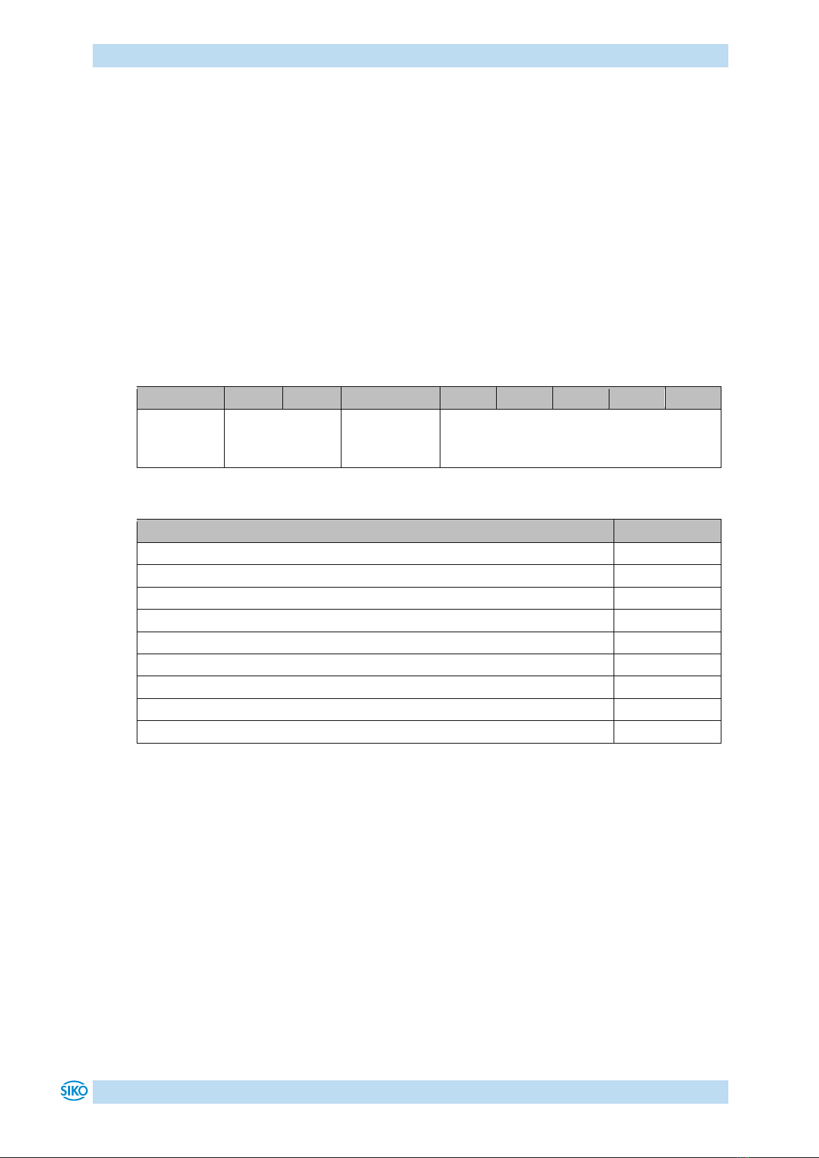
4.3 Reset to factory settings
To return to the original condition of the device as delivered, there exist the following
options:
Access
Coding
Settings are restored
CANopen (see object
1011h: Restore
Parameter)
1011h
"load"
Sub-index 1
All parameters
Sub-index 2
Only bus parameters
Sub-index 3
Only CiA 406 parameters
Sub-index 4
Only manufacturer-specific parameters
Table 6: Access to factory settings
5Communication via CAN bus (CANopen)
The CANopen communication profile CiA 301 V4.2, the Device profile for Encoders CiA 406
V3.2 as well as the indicator specification CiA 303 Part 3 V1.4.0 for CAN diagnosis form the
basis for the WV5800M / WH5800M. The WV5800M / WH5800M supports device class C2. The
details required for a better understanding of the operation are included in this
documentation. If more in-depth information is required, we recommend the applicable
technical literature on CAN or CANopen.
5.1 Telegram structure
The data telegram of a CAN message consists of the following fields:
SOF
Identifier (COB ID)
Control field
Data field (max. 8 byte)
CRC
ACK / EOF
SOF:
(Start of Frame) start bit of the telegram.
Identifier (COB ID):
By means of the identifier, all bus subscribers check whether the message is relevant for
each of them.
The identifier determines the priority of the message. The lower the value of the identifier,
the higher is the priority of the message. This enables preferential transmission of
important messages via the bus.
The Identifier field contains the identifier as well as bits for the recognition of the length of
the identifiers (11 or 29 bits). The device address, channel selection as well as data direction
are determined via the identifier as well.
Thus, the 11bits identifier (COB identifier) consists of a 4bit function code and a 7bit node
number:
Bit no.
10
9
8
7
6
5
4
3
2
1
0
Type
Functional code
Node number (Node ID)
Assignment
x
x
x
x
0
0
x
x
x
x
X

Communication via CAN bus (CANopen)
WV5800M/WH5800M Date: 29.07.2020 Art. No. 90107 Mod. status 170/20 Page 10 of 63
The following functional codes have been defined in the "Pre-defined Connection Set" (only
the functional codes used in the present device are shown):
Object
Functional code
Resulting COB ID
Object
Page
Network management (NMT)
0000b
0
-
11
SYNC message
0001b
128d (80h)
1005h
32
Emergency message
0001b
128d (80h) + Node ID
1014h
39
TPD01
0011b
384d (180h) + Node ID
1800h
41
TPD02
0101b
640d (280h) + Node ID
1801h
43
SDO (tx)
1011b
1408d (580h) + Node ID
1200h
41
SDO (rx)
1100b
1536d (600h) + Node ID
1200h
41
Heartbeat message
1110b
1792d (700h) + Node ID
-
20
Node Guard message
1110b
1792d (700h) + Node ID
-
20
LSS (tx)
-
2021d (7E4h)
-
21
LSS (rx)
-
2020d (7E5h)
-
21
Table 7: Overview of COB identifiers
Changes to COB IDs are only possible in the PRE-OPERATIONAL NMT status. First, the COB ID
must be switched invalid via bit 31 = 1b before it can be changed and reactivated.
The COB ID of the Sync object is an exception, where bit 30 must be = 0b to enable the COB
ID to be changed. As bit 30 cannot be set to 1b in the WV5800M / WH5800M, the COB ID
could be changed at any time.
The node number (Node ID) (see also object 5F0Ah: Node ID and baud rate Bus CAN) is
assigned once in every bus system with configuration of the master on WV5800M / WH5800M.
The node numbers range from 1 to 127. Node ID = 0 is reserved and must not be used.
The adoption of a node ID or baud rate which was reset occurs only after re-initialization
(see chapter 5.2.1).
The encoder WV5800M / WH5800M is delivered ex works with Node ID 1 (1h).
Control field:
Contains bit-by-bit information concerning the number of user data and determines whether a
data frame or RTR frame (Remote Transmission Request frame) is concerned.
Data field:
Contains up to 8 bytes of user data. The user data has a different meaning depending on the
channel selection.
CRC:
Contains bits for error detection.
ACK/EOF:
The ACK/EOF field contains telegram acknowledgment bits as well as bits for determining the
end of telegram.
For a detailed description of the telegram please refer to the applicable technical CAN
literature. For simplification, only identifier (COB ID) and data field will be dealt with in the
subsequent telegram descriptions.

Communication via CAN bus (CANopen)
WV5800M/WH5800M Date: 29.07.2020 Art. No. 90107 Mod. status 170/20 Page 11 of 63
5.2 Node control
5.2.1 Network management (NMT) services
The master configures, manages and monitors network nodes via the NMT service. The device
is always in one of the four communication states "INITIALISATION", "PRE-OPERATIONAL",
"OPERATIONAL" or "STOPPED" (see Fig. 3).
Fig. 3: NMT status diagram
5.2.1.1 NMT communication states
NMT Status INITIALISATION
The device is not involved in the bus actions in this state. All hardware and software
components are initialized. This state is attained after switching on the device or after receipt
of the command code 81h ("Reset node") of the own or global addresses. Following receipt of
the command code 82h ("Reset Communication"), the encoder will enter the initialization
stage as well. But only hardware and software associated with CAN communication will be
reinitialized. The device signals automatically the completion of initialization by sending a
boot-up message. As soon as the boot-up message was sent successfully, the device will enter
the "PRE-OPERATIONAL" status.
NMT Status PRE-OPERATIONAL
Parameterization data (SDO) can be exchanged in the pre-operational mode. However, no
process data (PDO's) is transferred.
Initialization
CAN-communication
Pre-Operational
Operational
Stopped
BootUp-Message
1
2
2
3
3
4
4
4
1
Re-initialization
CAN-card
5
5
5
Init
Power on or Software reset

Communication via CAN bus (CANopen)
WV5800M/WH5800M Date: 29.07.2020 Art. No. 90107 Mod. status 170/20 Page 12 of 63
NMT Status OPERATIONAL
The exchange of process data is enabled as well. However, COB ID and Transmit PDO Mapping
parameters can no longer be changed in this status.
NMT Status STOPPED
Communication is stopped except for heartbeat and node guarding Only NMT communication
is enabled.
5.2.1.2 Toggling between the NMT communication states
For toggling between the communication states, telegrams with the following structures are
used:
Change of state
Transition
in Fig. 3
COB
ID
Com-
mand
Node
ID
from
to
PRE-OPERATIONAL /
STOPPED
OPERATIONAL
1d
0h
01h
x
OPERATIONAL/ PRE-
OPERATIONAL
STOPPED
2d
0h
02h
x
OPERATIONAL / STOPPED
PRE-OPERATIONAL
3d
0h
80h
x
OPERATIONAL / PRE-
OPERATIONAL / STOPPED
INITIALISATION
(Reset Node)
5d
0h
81h
x
OPERATIONAL / PRE-
OPERATIONAL / STOPPED
INITIALISATION
(Reset Communication)
4d
0h
82h
x
Table 8: Toggling between communication states
If x = 0h is transferred as Node ID, then the message is intended for all bus subscribers.
5.2.2 Boot-Up
The COB ID of the boot-up message is made up of 700h and the Node ID. The "Initialization"
NMT status is output as data content.
COB ID
Byte 0
700h + Node ID
00h
Table 9: Boot-Up message
5.2.3 SYNC object
CANopen enables the simultaneous query of all inputs and the simultaneous setting of all
outputs. The synchronization message (SYNC), a CAN message with high priority serves this
purpose. The identifier of the Sync object can be set via object 1005h (see 1005h: COB ID
SYNC message).

Communication via CAN bus (CANopen)
WV5800M/WH5800M Date: 29.07.2020 Art. No. 90107 Mod. status 170/20 Page 13 of 63
5.3 Process data exchange
5.3.1 Transfer of process data objects (PDO)
Process data objects (PDO) serve for fast exchange of process data. A maximum of 8 bytes of
user data can be transferred in a PDO. The WV5800M / WH5800M supports the Transmit PDO
services TPDO1 and TPDO2 according to CiA 301 and CiA 406.
5.3.1.1 Transmit-PDO (from the WV5800M / WH5800M to the master)
PDO transfer from the display to the bus master (TPDO) can be initiated as a result of various
events:
asynchronous, controlled by an internal device timer
synchronous as a response to a SYNC telegram
as a response to an RTR message
TPDO1 and TPDO2 are generated from the position value and the speed value. The transfer
behavior of TPDO1 is determined via the objects 1800h, 1A00h and 6200h and is assigned to
asynchronous transmission. TPDO2 is defined via the objects 1801h and 1A01h and serves
synchronous transmission. Assignment is static and cannot be changed.
Messages are structured as shown in Table 10.
COB ID
Process data in binary code
Byte 0
(LSB)
Byte 1
Byte 2
Byte 3
(MSB)
Byte 4
(LSB)
Byte 5
(MSB)
TPDO1
180h + Node ID
Position value
Speed value
TPDO2
280h + Node ID
Table 10: TPDO message
Asynchronous data transmission (TPDO1)
If a TPDO1 is to be sent cyclically, then the cycle time must be entered in milliseconds into
object 1800h, sub-index 05h. The TPDO1 will not be sent if the value 0 ms is written. The
function is disabled. The minimum value to be set is 1h (= 1 ms). Alternately, the value can
also be written into the permanently internally linked object 6200h.
Synchronous data transfer (TPDO2)
As delivered, the device responds to every SYNC Message received with the output of the
TPDO2 message. 1h is entered for synchronous transmission in object 1801h, sub-index 02h.
If a value n is entered between 1d and 240d (= F0h), the device will respond to every nth
SYNC message.
RTR
Queries can be sent via RTR (see chapter 5.1) toTPDO1 and TDPO2.

Communication via CAN bus (CANopen)
WV5800M/WH5800M Date: 29.07.2020 Art. No. 90107 Mod. status 170/20 Page 14 of 63
5.4 Parameter data exchange
5.4.1 Transmission of Service Data Objects (SDO)
Service data objects serve mainly device configuration via the directory of objects. SDOs in
the expedited Request/Response and in the normal Request/Response are supported.
The identifier is set to 11 bits and cannot be changed.
Two SDO services are available:
SDO (rx) (Master WV5800M / WH5800M): 600h + Node ID
SDO (tx) (WV5800M / WH5800M Master): 580h + Node ID
Two SDO services are available!
5.4.1.1 Expedited Request/Response
Except for reading the object 1008h: Manufacturer Device Name, all SDOs are exchanged
between two subscribers in the expedited Request/Response method. The user data is
provided already with the initialization message.
SDO messages are set up as follows:
COB ID
User data in binary code
Byte 0
read /
write
Byte 1
LSB
Byte 2
MSB
Byte 3
Byte 4
LSB
Byte 5
Byte 6
Byte 7
MSB
SDO rx/tx
+ Node ID
Command
byte
Index
Sub-index
User data (parameter)
Command byte, byte 0:
The command byte determines the type of access and the number of valid data bytes. The
following command bytes are valid for the WV5800M / WH5800M:
Command byte
Type
Function
Write Request
23h
SDO (rx), Initiate Download
Request, expedited
Send parameter to slave
(all 4 data bytes valid)
Write Request
2Bh
SDO (rx), Initiate Download
Request, expedited
Send parameter to slave
(2Bytes of 4 data bytes valid)
Write Request
2Fh
SDO (rx), Initiate Download
Request, expedited
Send parameter to slave
(1Byte of 4 data bytes valid)
Write Response
60h
SDO (tx), Initiate Download
Response
Acknowledgment of data
acquisition to master
Read Request
40h
SDO (rx), Initiate Upload
Request
Request parameter from slave
Read Response
43h
SDO (tx), Initiate Upload
Response, expedited
Report parameter to master
(all 4 data bytes valid)
Read Response
4Bh
SDO (tx), Initiate Upload
Response, expedited
Report parameter to master
(2Bytes of 4 data bytes valid)

Communication via CAN bus (CANopen)
WV5800M/WH5800M Date: 29.07.2020 Art. No. 90107 Mod. status 170/20 Page 15 of 63
Command byte
Type
Function
Read Response
4Fh
SDO (tx), Initiate Upload
Response, expedited
Report parameter to master
(1Byte of 4 data bytes valid)
Error Response
80h
SDO (tx), Abort Domain
Transfer
Slave reports error code to master
Table 11: Command coding
Index, bytes 1 and 2:
The index (object number) is entered in the user data byte 2 (low byte) and user data byte 3
(high byte) in the Intel data format. Here, the index of the object to be parameterized is
entered.
Sub-index, byte 3:
The sub-index indicates the number of the fields for objects realized as an array.
User data (parameters), bytes 4 … 7:
In the user data, the value of the parameter is entered in left-aligned Intel notation. Byte 4 =
Low-Byte ... Byte 7 = High-Byte.
5.4.1.2 Normal Request/Response
If more than 4 bytes of service data are to be transferred, the data is exchanged between two
subscribers via the normal Request/Response. This procedure is also initiated by an
initialization message, and the actual user data will be transferred in the subsequent segment
messages.
For the WV5800M / WH5800M this is only the case with reading of the object 1008h:
Manufacturer Device Name.
The initialization message has the following structure:
COB ID
User data in binary code
Byte 0
read /
write
Byte 1
LSB
Byte 2
MSB
Byte 3
Byte 4
LSB
Byte 5
Byte 6
Byte 7
MSB
SDO rx/tx
+ Node ID
Command
byte
Index
Sub-index
User data (number of user data)
The segment message has the following structure:
COB ID
User data in binary code
Byte 0
read /
write
Byte 1
LSB
Byte 2
Byte 3
Byte 4
Byte 5
Byte 6
Byte 7
MSB
SDO rx/tx
+ Node ID
Command
byte
User data

Communication via CAN bus (CANopen)
WV5800M/WH5800M Date: 29.07.2020 Art. No. 90107 Mod. status 170/20 Page 16 of 63
Initialization and segment message: Command byte, byte 0:
The command byte determines the type of access and the number of valid data bytes. The
following command bytes are valid for the WV5800M / WH5800M:
Command byte
Type
Function
Read Request
40h
SDO (rx), Normal Initiate
Upload Request
Request parameter from slave
(number of bytes to be transferred)
Read Request
60h
SDO (rx), Normal Segment
Upload Request
Request parameter from slave (user
data)
Read Response
41h
SDO (tx), Normal Initiate
Upload Response
Report parameter to master (number
of bytes to be transferred)
Read Response
03h
SDO (tx), Normal Segment
Upload Response
Report parameter to master (user
data)
Error Response
80h
SDO (tx), Abort Domain
Transfer
Slave reports error code to master
Table 12: Command coding
Initialization message: Index, bytes 1 and 2:
The index (object number) is entered in the user data byte 2 (low byte) and in the user data
byte 3 (high byte) in the Intel data format. Here, the index of the object to be parameterized
is entered.
Initialization message: Sub-index, Byte 3:
The sub-index indicates the number of the fields for objects realized as an array.
Initialization message: User data (parameters), byte 4 … 7:
In the service data range, the value of the parameter is entered in left-aligned Intel notation.
Byte 4 = Low-Byte ... Byte 7 = High-Byte.
Segment message: User data (parameters), byte 1 … 7:
In the user data range, the value of the parameter is entered in left-aligned Intel notation.
Byte 1 = Low-Byte ... Byte 7 = High-Byte.
5.4.1.3 Error Response in SDO exchange
With invalid access, an error message (Abort) is returned to the master.
The error codes are described in the CANopen profile (CiA 301) or in the encoder profile (CiA
406), respectively. The table below shows the error codes used:
Error code
Description
05030000h
Toggle bit in Normal Transfer of Request/Response unequal.
06010000h
Wrong access to an object.
06010001h
Read access to Write-Only.
06010002h
Write access to Read-Only.
06020000h
Object doesn't exist in the object directory.
Communication via CAN bus (CANopen)
WV5800M/WH5800M Date: 29.07.2020 Art. No. 90107 Mod. status 170/20 Page 17 of 63
Error code
Description
06090011h
Sub-index does not exist.
06090030h
Wrong value range of selected parameter.
08000020h
Parameters cannot be transferred to application or stored.
08000022h
Parameters cannot be transferred to application or stored due to the current
device status.
08000024h
No data available
Table 13: Error codes
5.4.1.4 SDO examples
Example of reading SDO parameters with the expedited Request/Response:
The calibration value stored in object 6003 of the directory of objects is to be read from the
slave with device address 1h.
Calculation of the identifier: 600h + Node ID = 600h +1h = 601h
Command: 40h
Index: 6003h
Sub-index: 00h
The current value is 510d = 01FEh
Request of master from slave with Node ID 1h:
COB ID
User data
Command
Index L
Index H
Sub-index
Data 0
Data 1
Data 2
Data 3
601h
40h
03h
60h
00h
x
x
x
x
Response to the request by the slave:
Calculation of the identifier: 580h + Node ID = 581h
COB ID
User data
Command
Index LB
Index HB
Sub-index
Data 0
Data 1
Data 2
Data 3
581h
43h
(4 bytes
valid)
03h
60h
00h
FEh
01h
00h
00h
Example of writing SDO parameters with the expedited Request/Response:
In the slave with device address 1h the cycle timer, which is stored with 2 bytes in object
6200h of the object dictionary, is to be changed.
Calculation of the identifier: 600h + Node ID = 600h + 1h = 601h
Command: 2 bytes are to be written: 2Bh
Index: 6200h
Sub-index: 00h
The new value shall be 4500d = 1194h

Communication via CAN bus (CANopen)
WV5800M/WH5800M Date: 29.07.2020 Art. No. 90107 Mod. status 170/20 Page 18 of 63
Writing of a value from master to slave with Node ID 1h:
COB ID
User data
Command
Index L
Index H
Sub-index
Data 0
Data 1
Data 2
Data 3
601h
2Bh
(2 bytes
valid)
00h
62h
00h
94h
11h
00h
00h
Response to the command by the slave:
Calculation of the identifier: 580h + Node ID = 580h + 1h = 581h
COB ID
User data
Command
Index L
Index H
Sub-index
Data 0
Data 1
Data 2
Data 3
581h
60h
00h
62h
00h
00h
00h
00h
00h
Example of reading SDO parameters with normal Request/Response:
The manufacturer device name stored in object 1008h of the directory of objects is to be read
from the WV5800M / WH5800M with device address 1h.
Calculation of the identifier: 600h + Node ID = 600h +1h = 601h
Command: 40h
Index: 1008h
Sub-index: 00h
First request (= initialization) of master from slave with Node ID 1h:
COB ID
User data
Command
Index L
Index H
Sub-index
Data 0
Data 1
Data 2
Data 3
601h
40h
08h
10h
00h
x
x
x
x
Response to the request by the slave:
Calculation of the identifier: 580h + Node ID = 581h:
COB ID
User data
Command
Index LB
Index HB
Sub-index
Data 0
Data 1
Data 2
Data 3
581h
41h
08h
10h
00h
07h
00h
00h
00h
Number of expected user data bytes: 7
Second request of master from slave with Node ID 1h:
COB ID
User data
Command
Index L
Index H
Sub-index
Data 0
Data 1
Data 2
Data 3
601h
60h
08h
10h
00h
x
x
x
x
Response to the request by the slave:
COB ID
User data
Command
Data 0
Data 1
Data 2
Data 3
Data 4
Data 5
Data 6
581h
01h
57h
("W")
56h/48h
("V")/("H")
35h
("5")
38h
("8")
30h
("0")
30h
("0")
4Dh
("M")
Communication via CAN bus (CANopen)
WV5800M/WH5800M Date: 29.07.2020 Art. No. 90107 Mod. status 170/20 Page 19 of 63
5.5 Node monitoring
5.5.1 Emergency service (EMCY)
In the case of an error, the status of the bus subscriber is transferred via high-priority
emergency messages (emergency telegrams). These messages have a data length of 8 bytes
and contain error information.
The emergency message is transferred as soon as a sensor or communication error has
occurred or when such errors have been corrected. The cause of the error is deposited in the
error buffer (see object 1003h: Pre-defined Error Field). An emergency object is sent only once
per error event. Removal of the cause of the error is signaled by sending an emergency
message with the error code 0000h (no error). If multiple errors have occurred and one cause
of error is removed, the error code 0000h is output as well; the persisting error status is
indicated in the error register, however.
Identifier
Byte 0
Byte 1
Byte 2
Byte 3
Byte 4
Byte 5
Byte 6
Byte 7
11/ 29 Bit
Emergency Error
Code
Error Register
(object
1001h)
Manufacturer-specific error field
(not used)
Emergency Error Code:
Error Description
Error Code
Cause of the error removed
0000h
Bus status changed over to the error passive mode
8120h
Recovered from Bus Off
8140h
Manufacturer specific: Position value error
FF05h
Manufacturer specific: Velocity error
FF12h
Manufacturer specific: Error limit speed low
FF13h
Manufacturer specific: Error limit speed high
FF14h
Manufacturer specific: Position error work area 1
FF15h
Manufacturer specific: Position error work area 2
FF16h
Table 14: Emergency Error Code
The identifier of the emergency object is set to 80h + Node ID by default; however, it can be
changed via object 1014h (see 1014h: COB ID Emergency message). Transmission of an
emergency message is enabled in the NMT statuses "OPERATIONAL" or "PRE-OPERATIONAL"
only! Transmission of the emergency messages can be disabled by setting the COB ID Valid bit
to 1.

Communication via CAN bus (CANopen)
WV5800M/WH5800M Date: 29.07.2020 Art. No. 90107 Mod. status 170/20 Page 20 of 63
5.5.2 Node Guarding
Node guarding is available for failure monitoring of the CANopen network. During node
guarding, the master transmits remote frames (RTR, remote transmit request, message request
telegrams) on the guarding identifiers of the nodes to be monitored. The latter respond with
the guarding message. This message contains the current NMT status of the node as well as a
toggle bit whose value must change after each message. The master assumes that a node error
has occurred if status or toggle bits do not correspond with those expected by the master or if
there is no response.
Via objects 100Ch (Guard Time) and 100Dh (Life Time Factor) the time interval (Life-Time) is
set within which the NMT master expects to receive a response. The time interval "Life Time"
is calculated from the cycle time "Guard Time", multiplied with the factor "Life Time Factor".
If the NMT master does not receive a response to its RTR frame within the "Life Time", it may
react with suitable measures. Upon switching on, node guarding will be enabled by sending
the first RTR frame of the master to the slave. Node Guarding is deactivated if the value of
either object (100Ch or 100Dh) is set to 0h.
The answer of the node to the RTR frame of the master is formed as follows:
Identifier
Byte 0
700h + Node ID
Bit 7: Toggle Bit
Bit 6 … 0: NMT state
Toggle Bit:
The toggle bit must alternate between two subsequent responses of the device. After the
guarding protocol has been enabled, the toggle bit must have the value 0 with the first
response.
NMT state:
4: STOPPED
5: OPERATIONAL
127: PRE-OPERATIONAL
The identifier of the node guarding protocol is permanently set to 700h + Node ID and cannot
be changed. A node guard message can be sent in the NMT statuses "OPERATIONAL", "PRE-
OPERATIONAL" or "STOPPED".
Note:
Literature recommends heartbeat to be used for node monitoring. Only the master can detect
missing communication via the node guarding protocol as opposed to the heartbeat that can
be received by all subscribers.
5.5.3 Heartbeat
The master monitors the state of the slave device via Heartbeat protocol. While doing this,
the device sends independently its NMT status cyclically. The WV5800M / WH5800M is a
heartbeat producer, it does not receive nor process heartbeat protocols itself. The cycle time
of the heartbeat message is set via object 1017h. The heartbeat protocol is deactivated if the
cycle time is 0h.
Other manuals for WV5800M
2
This manual suits for next models
1
Table of contents
Other Siko Media Converter manuals


