6
GENERAL FEATURES
Description of components
Indoor unit structure Basement, lateral panels and frontal
panel, are completely thermally and acoustically insulated in
order to minimize thermal losses and noise emissions in the
surroundings. Accessibility to internal parts is possible removing
the frontal panel and the upper panel. For extraordinary
manteinances also the rear panel can be removed.
Outdoor unit structure Basement, supporting structure and
lateral panels are made of galvanized and painted sheet-steel to
guarantee good resistance to atmospheric agents. Accessibility
to internal parts is possible removing the frontal panel. For
extraordinary manteinances also the other panels can be
removed.
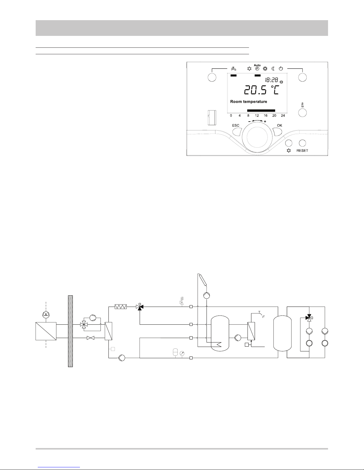
Refrigerant circuit All the components of the refrigerant circuit,
except the finned coil, are contained inside an extractable box
placed in the indoor unit to simplify the maintenance operations.
The box is placed on rubber vibration dampers and is connected
to the hydraulic circuit through flexible pipes in order to avoid
the propagation of the vibrations generated by the compressor
outside the unit. The hermetic rotary compressor (1) is mounted
on damper supports and is protected against overtemperatures
and overcurrents. The heat exchangers on the plant side (2) is
a brazed stainless steel plate heat exchanger, properly insulated
to avoid condensate generation and to minimize thermal losses,
and protected by a flow switch that detects whatever water
flow lack. The source side heat exchanger (3) is a finned coil
realized with grooved copper pipes and hydrophilic aluminium
fins with waved profile to increase the heat exchange coefficient.
A tray is placed under the coil to collect the condensate generated
in heating mode. The expansion device (4), an electronic
expansion valve, allows the unit to adjust itself to the different
operating conditions keeping steady the set superheating. The
refrigerant circuit of each unit contains moreover solid core
hermetic filter dryer (5) to restrain impurity and moisture
residuals that could be present in the circuit, high and low
pressure switches in order to assure the compressor to operate
inside the permitted limits, 4 way reverse cycle valve (6) to
allow operating mode change reversing the refrigerant flow,
pressure connections SAE 5/16” - UNF 1/2” - 20 equipped
with pin, gasket and blind nut, as required for the use of R410A
refrigerant (they allow the complete check of the refrigerant
circuit : compressor inlet pressure, compressor outlet pressure,
thermostatic expansion valve upstream pressure and pressure
drops accross the filter). All the pipes of the refrigerant circuit
are properly insulated to avoid condensate generation and to
minimize thermal losses.
The axial fan (8) is equipped with an high efficiency electronically
commutated (EC) motor, is contained ia a sheet nozzle and is
equipped with a safety grille.
Hydraulic circuit All the pipes are thermally insulated to avoid
condensate generation and minimize thermal losses. The circuit
is equipped with a three speed glandless pump, expansion
vessel, safety valve, pressure gauge and air vents.
Electrical panel. It contains all the power, control and security
components necessary to guarantee the unit to work properly.
The unit is managed by a microprocessor controller to which
all the electrical loads and the control devices are connected.
The user interface, placed on the frontal panel of the unit, allows
to view and to modify, if necessary, all the parameters of the unit.
All the units are supplied with an outdoor temperature sensor,
to be installed outside, in order to realize the climatic control.
1
72
6
4
5