3
EN
Cod. 3542B250 - Rev. 00 - 02/2022
OMNIA S HYBRID C 3.2
SUMMARY
1. SAFETY PRECAUTIONS ..........................................................................................5
1.1 Special requirements for R32 refrigerant ....................................................................... 6
1.2 Information servicing .................................................................................................... 13
2. GENERAL FEATURES............................................................................................16
2.1 Presentation of the system........................................................................................... 16
2.2 Components supplied with the indoor unit ................................................................... 17
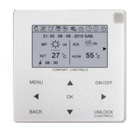
2.3 User interface ............................................................................................................... 17
2.4 Accessories .................................................................................................................. 18
2.4.1 Hydraulic kit .................................................... 18
2.4.2 Fittings cover kit................................................. 18
3. TECHNICAL DATA AN PERFORMANCE..............................................................19
3.1 Heat pump technical data............................................................................................. 19
3.2 ERP data ...................................................................................................................... 20
3.3 Heat pump operational limits........................................................................................ 20
3.4 Boiler technical data ..................................................................................................... 21
3.4.1 Table for boiler technical data ...................................... 21
3.4.2 Boiler ErP product data sheet ...................................... 22
3.5 Available pressure ........................................................................................................ 23
3.5.1 Heat pump circulator + boiler circulator............................... 23
3.5.2 Heat pump circulator ............................................ 23
3.5.3 Boiler circulator ................................................. 23
4. DIMENSIONAL AND PHYSICAL DATA.................................................................24
5. GENERAL VIEW AND INTERNAL UNIT FUNCTIONAL DIAGRAM...................25
5.1 General view ................................................................................................................ 25
5.2 Indoor unit functional diagram ...................................................................................... 25
6. EXAMPLE OF SYSTEM LAYOUT ..........................................................................26
7. INSTALLATION .......................................................................................................27
7.1 Inspections on arrival ................................................................................................... 27
7.1.1 Packing and storing .............................................. 27
7.1.2 Selecting the installation site and minimum operating area for indoor unit .... 27
7.2 Limits to the length and height dierence of refrigerant pipes...................................... 29
7.3 Refrigerant connections ............................................................................................... 30
7.3.1 Airtight test and leakage detection................................... 31
7.3.2 Air purge with vacuum pump ....................................... 31
7.3.3 Heat insulation.................................................. 32
7.3.4 Refrigerant amount to be added .................................... 32
7.4 Hydraulic connections .................................................................................................. 32
7.4.1 Antifreeze system, antifreeze uids, additives and inhibitors .............. 32
7.4.2 Characteristics of the system water.................................. 32
7.4.3 Water lter ..................................................... 33
7.4.4 Tips for a successful installation .................................... 33
7.4.5 Filling with water ................................................ 34
7.4.6 Water circuit anti-freeze protection .................................. 34
7.4.7 Water piping insulation ........................................... 34
7.5 Boiler gas connection ................................................................................................... 35
7.6 Boiler fume ducts.......................................................................................................... 35
7.6.1 Warnings ...................................................... 35
7.6.2 Connection with coaxial pipes ...................................... 35
7.6.3 Connection with separate pipes .................................... 36
7.6.4 Use of exible hose pipe Ø50 and Ø60............................... 38
7.6.5 Connection to collective chimneys .................................. 39
7.7 Connection to boiler condensate discharge ................................................................. 40
7.8 Electrical connections................................................................................................... 40
7.8.1 Electrical data .................................................. 40
7.8.1 Opening the front panel ........................................... 42
7.8.2 User terminal block connections .................................... 42
H-L1-C - Digital inputs for room thermostat.............................. 42
7.8.2 Connection of system add-ons ..................................... 43
7.8.3 How to access the heat pump hydronic board ......................... 43
7.8.4 Heat pump hydronic board ........................................ 44
7.8.5 Connections to the heat pump board ................................ 46
P_o - For outside circulation pump or water pump zone 1 .................. 46
P_c - Water pump of zone 2 ......................................... 46
SV3 - 3-way mixing valve for zone 2 ................................... 46
SV2 - 3-way diverter valve for heat/cool ................................ 46
SG Digital inputs for smart grid input from mains electricity ................. 46
Additional temperature probes ....................................... 46
8. USER INTERFACE...................................................................................................47
8.1 Key function description ............................................................................................... 47
8.2 Meaning of display icons .............................................................................................. 47
8.3 Switching DHW and system on and o ........................................................................ 48
8.4 DHW and system set point conguration ..................................................................... 49
9. GENERAL USER MENU..........................................................................................50
9.1 Boiler menu .................................................................................................................. 50
9.1.1 User boiler menu ................................................ 50
9.1.2 Boiler service menu .............................................. 51
Menu for modifying the [TSP] parameters............................... 51
9.2 Heat pump menu.......................................................................................................... 53
9.2.1 User heat pump menu (hp menu) ................................... 53
Heat / Cool operating mode selection (Operation Mode) ................... 56
Daily schedule / climatic curves / Eco mode (Preset Temp) ................. 56
Cool mode weekly schedule (Preset Temp. Cool)......................... 57
Heat mode weekly schedule (Preset Temp. Heat) ........................ 57
Climate curves (Weather Temp Set) ................................... 57
Economy mode (Eco Mode) ......................................... 57
Silent Mode ...................................................... 57
Holiday mode..................................................... 58
Error code ....................................................... 58
Parameters ...................................................... 58
Display.......................................................... 58
Operation Parameter............................................... 58
9.2.2 Heat pump service menu.......................................... 59
10. SETTINGS TO ENTER BEFORE STARTING UP ...............................................62
10.1 Dip switch setting on indoor unit hydronic board........................................................ 62
10.2 Dip switch setting of outdoor unit cooling circuit board .............................................. 63
10.3 Climatic curves ........................................................................................................... 63
10.3.1 Temperature curves for heating mode and ECO heating mode ........... 63
Climatic curve 9 in heating mode settable by the user ..................... 64
10.3.2 Temperature curves for cooling mode ............................... 65
Climatic curve 9 in cooling mode settable by the user ..................... 65
