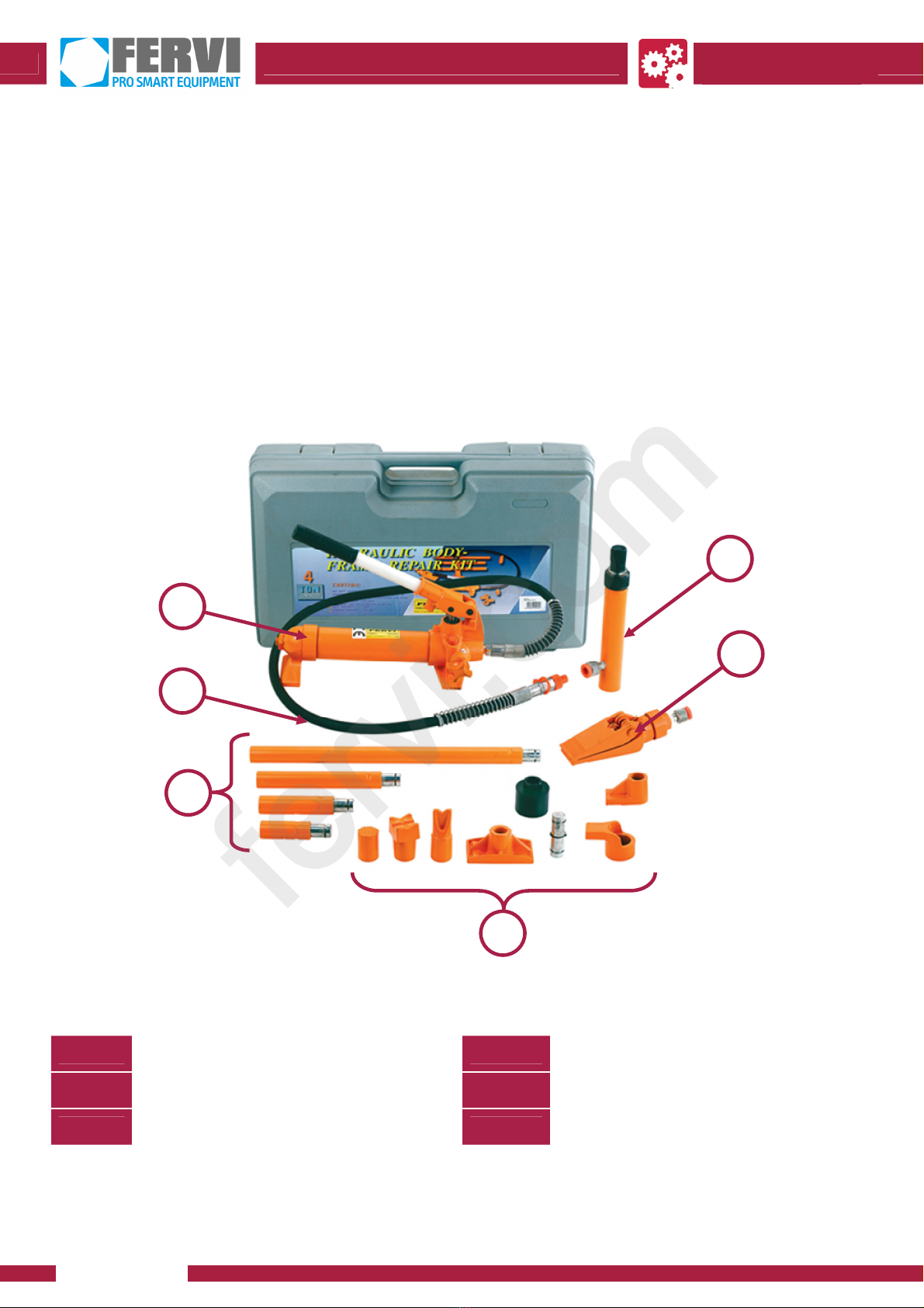
Fervi 0054/10 User manual

OPERATION AND
MAINTENANCE MANUAL
Hydraulic body frame repair kit
Art. 0054/10
ORIGINAL INSTRUCTIONS
fervi.com

MACHINES AND
ACCESSORIES
Page 2 of 17
FOREWORD
Read this manual before operating any machinery
ORIGINAL INSTRUCTIONS
Before starting any operation it is compulsory to read this instruction manual. The guarantee
that the machine will function and perform properly is strictly dependent upon the application
of all the instructions contained in this manual.
Operator Qualification
The operators assigned to using this machine must be supplied with all of the necessary
information and instruction and should be provided with adequate training regarding
safety in pertaining to:
a) The conditions of use of the equipment;
b) Foreseeable abnormal situations, pursuant to Article 73 of Legislative Decree
81/08.
We guarantee the Machine's conformity to the specifications and technical instructions
described in the Manual on the date of issuance and listed herein; On the other hand,
the machine may also be subject to important technical changes in the future, without
the manual being updated.
Therefore, see FERVI for information about modifications that could be implemented.
REV. 2 November 2013
fervi.com

MACHINES AND
ACCESSORIES
Page 3 of 17
CONTENTS
1 GENERAL INFORMATION........................................................................... 4
2 GENERAL SAFETY WARNINGS ................................................................... 5
2.1 Technical support..........................................................................................................5
2.2 Other provisions ...........................................................................................................5
3 DESCRIPTION OF THE HYDRAULIC UNIT .................................................. 6
3.1 Identification Plate and Pictograms ..............................................................................7
3.2 Safety devices...............................................................................................................7
4 TECHNICAL SPECIFICATIONS ................................................................... 8
5 IMPROPER USE AND CONTRAINDICATIONS.............................................. 8
6 TRANSPORTING, LIFTING AND MOVING ................................................... 9
7 USING THE HYDRAULIC BODY FRAME REPAIR KIT ................................... 9
7.1 Commissioning............................................................................................................ 10
7.2 Pressure Release ........................................................................................................11
8 MAINTENANCE ........................................................................................ 11
9 TROUBLESHOOTING................................................................................ 13
10 WAREHOUSE STORAGE......................................................................... 13
11 DECOMMISSIONING ............................................................................. 13
12 REPLACEMENT PARTS........................................................................... 14
12.1 General .................................................................................................................... 14
12.2 Hydraulic cylinder .................................................................................................... 15
12.3 Pump ....................................................................................................................... 16
fervi.com

MACHINES AND
ACCESSORIES
Page 4 of 17
1 GENERAL INFORMATION
This manual is delivered with the machine, and it must be regarded as an inseparable part of
it.
The manufacturer holds all ownership to material and intellectual property of this manual;
any disclosure or copying, even partial, of this publication without prior written consent is
forbidden.
The purpose of this manual is to provide the knowledge necessary for the use and
maintenance of the Hydraulic body frame repair kit Art. 0054/10, and create a sense of
responsibility and a knowledge of the possibilities and limitations of the tool entrusted to the
operator.
Operators must be properly trained and prepared, so make sure that this manual is read and
consulted by the staff responsible for commissioning, operation and maintenance of the
pump. This is to make all operations the safest and most effective possible for those who
carry out these tasks. Therefore, it is imperative to strictly comply with the requirements in
this manual, a necessary condition for safe and satisfactory operation of the pump.
Before using the machine, authorized personnel must:
carefully read this technical document;
know which protections and safety devices are available, their location and how they
work.
The users must be properly trained, that they are aware of all the information and
instructions in this manual and are aware of the potential risks of operating the pump.
The manufacturer waives any and all responsibility for damage to people and/or
things caused by non-observance of the instructions in this manual.
Users will be held fully responsible for any changes made to the trolley and the
manufacturer will not, therefore, be held responsible for any damage caused to
persons and/or property resulting from maintenance performed by unqualified
personnel and in a manner that differs from the operating procedures shown below.
The pump is equipped with safety devices and labels which are there to protect and inform
the user, so as to avoid possible physical damage.
It is strictly forbidden to modify or remove safety devices and caution labels. If this must be
done (for example, for cleaning or repair), make sure that no one can use the pump.
GRAPHIC FORM OF THE ALERTS RELATED TO SAFETY AND OPERATION,AND RISK WARNINGS
The following boxes are designed to attract the attention of the reader/user for the purposes
of proper and safe use of the machine:
Pay attention
This highlights behavioural rules to prevent damage to the machine and/or the occurrence of
dangerous situations.
Residual Risks
This highlights the presence of dangers that cause residual risks to which the operator must
pay attention in order to avoid injury or damage to property.
fervi.com

MACHINES AND
ACCESSORIES
Page 5 of 17
2 GENERAL SAFETY WARNINGS
Even if you are already familiar with the Hydraulic Pump, you must read this manual
carefully to acquire full knowledge of the machine and general precautions to be observed
during operation.
Risks related to Using the Machine
For safe use of the pump, it is necessary to take note of all the requirements for the
prevention of accidents detailed in the various sections of this manual.
The pump must only be used by personnel who have been specially trained by
authorized personnel.
Only use the pump with single-acting cylinders.
Before starting work, make sure that the pump is in good condition.
Do not adjust the safety valve!
Place the pump on a flat, solid and durable work surface.
Do not try to operate the machine at higher performance levels than those for which it
was designed, in particular regarding the magnitude of the load to be lifted. In
other words, do not load the pump beyond its capacity.
If you use the pump to lift a vehicle, lock the wheels of the vehicle with the parking
brake.
Always use a safety support, such as a tripod, to support the load in case you
need to work under the load.
It is recommended that users of this publication, for maintenance and repair, have a
basic knowledge of mechanical principles and of repair technique procedures.
Replace worn or damaged parts, check that the repairs and protection work correctly
before operating.
Make sure that the work environment is forbidden to children, non-employees and
animals.
2.1 Technical support
For any problems or concerns, please do not hesitate to contact the dealer who sold the item.
2.2 Other provisions
The first thing to do when starting work is to check the presence and integrity of the
protections and the operation of the safety devices.
Do not use the Pump if it is defective!
fervi.com

MACHINES AND
ACCESSORIES
Page 6 of 17
3 DESCRIPTION OF THE HYDRAULIC UNIT
The hydraulic unit Art. 0054/10 is designed to provide pressure to cylinders or single-acting
hydraulic tools.
The pump must be used on surfaces that are supportive, flat, smooth, and adequately strong
and hard.
The operating temperature is within the range of –20/+50°C.
The working environment must also be sufficiently well lit to ensure maximum operational
safety (at least 200 lux are recommended).
Other types of use, or the extension of use beyond that envisaged, does not
correspond to the designation attributed by the manufacturer, and therefore the
latter cannot accept any responsibility for any damage resulting therefrom.
Figure 1 – General view
1Hydraulic pump 4Accessories
2Hose 5Hydraulic cylinder
3Set of extensions 6Separator wedge
1
2
3
4
5
6
fervi.com

MACHINES AND
ACCESSORIES
Page 7 of 17
3.1 Identification Plate and Pictograms
The identification plate is affixed to the hydraulic cylinder.
Figure 2 – Identification plate.
MAXIMUM NOMINAL CAPACITY
The plate indicates the maximum thrust capacity, that the pump in combination with the
supplied hydraulic piston can produce in standard conditions, i.e. when:
it is in good conditions of efficiency and conservation;
is applied to a flat, hard and durable surface.
The maximum nominal capacity must never be exceeded!!
3.2 Safety devices
The flexible tube that carries the high-pressure hydraulic oil, is connected by an external hose
and protected by a metal connector, which is adapted to prevent excessive bending at the
connection points.
Figure 3 – Hose protector.
Pump Overload
It is strictly forbidden to alter or modify the hose.
The tube should only be replaced with one of equal characteristics.
fervi.com

MACHINES AND
ACCESSORIES
Page 8 of 17
4 TECHNICAL SPECIFICATIONS
Description Unit of measurement Art. 0054/10
Lifting capacity kg 10,000
Pressure MPa 63.7
Piston Height mm 390
Piston stroke mm 150
Kit weight kg 33
5 IMPROPER USE AND CONTRAINDICATIONS
THE FOLLOW ARE STRICTLY PROHIBITED!:
Using the hydraulic body frame repair kit to lift persons and/or animals that could fall.
Using the hydraulic body frame repair kit to lift loads while people are passing near the
machine.
Working under lifted loads without using additional safety supports, such as a tripod.
Exceeding the maximum capacity of the pump, as indicated on the identification plate.
Lifting "dangerous" loads (molten metals, acids, radio-active materials, fragile and/or
crumbly).
Leaving the hydraulic body frame repair kit unattended while under pressure.
Allowing untrained personnel to use the pump.
Using the hydraulic body frame repair kit if you are not mentally and physically capable
of doing so.
Using the hydraulic body frame repair kit without due care.
Using the hydraulic body frame repair kit other than for its intended use;
Using the hydraulic body frame repair kit in environmental conditions for which it was
not intended (poor weather conditions, refrigerators, high magnetic fields, etc.).
Using the hydraulic body frame repair kit in potentially explosive environments.
Using the hydraulic body frame repair kit in the event of insufficient lighting.
Using the hydraulic body frame repair kit on ships at open sea.
Allowing the hydraulic body frame repair kit to come into contact with foodstuffs.
fervi.com

MACHINES AND
ACCESSORIES
Page 9 of 17
6 TRANSPORTING, LIFTING AND MOVING
The operator may manually lift the pump for transporting. Make sure the drain valve screw is
fully tightened.
The operator should grasp the pump with both hands, using the lever and the base of the
hydraulic cylinder as lifting points.
Avoid Dropping to Protect Feet from Crushing
Move the pump by holding it with both hands, one on the gripping handle and one
below the hydraulic cylinder.
Do not hold with just one hand. It could fall and crush your feet!
The hydraulic body frame repair kit is provided with
a mould case with wheels which are useful for
moving the kit. Hold the case by the upper handle
and pull it along with the case behind you.
Figure 4 – Moving the case.
7 USING THE HYDRAULIC BODY FRAME REPAIR KIT
Avoid Crushing Body Parts
There is a risk of crushing body parts while lifting heavy loads resulting from
mishandling. Workers must be equipped with standard safety equipment, such as
gloves and crush resistant shoes.
Workers involved in load lifting must operate the pump carefully and pay the utmost
attention.
In particular, the pump, lift and load should be controlled during movement.
It is absolutely forbidden to work under a load that is lifted and supported only by a
hydraulic lift.
Hose Rupture
Before operating the pump, check the integrity and correct mounting of the hose.
fervi.com

MACHINES AND
ACCESSORIES
Page 10 of 17
7.1 Commissioning
To commission the hydraulic body frame repair kit for use, it is necessary to do the following:
1. Take out all the necessary components from the
case. Verify the presence of all the components.
F
igure 5 - Mould case
2. Place the pump on a uniform surface that is
strong enough for the task to be performed.
3. Check the oil level in the tank by lifting the
appropriate cap, and eventually fill the tank up to
the optimum level.
4. Install the operating lever by inserting it in its
special housing and turning it clockwise to lock it
F
i
g
ure 6 – Installing the lever.
5. Remove the protective cap from the hydraulic
hose and connect it to a cylinder or a lifting
accessory.
6. Make sure that the vent valve is closed by
turning the control knob clockwise. (Figure 7)
7. To pressurise the pump, raise the rod on the
hydraulic cylinder by manually operating the
pumping lever on the piston pump. Continue
pumping until the desired height is reached.
F
igure 7 – Control knob.
fervi.com

MACHINES AND
ACCESSORIES
Page 11 of 17
7.2 Pressure Release
To lower the piston rod on the hydraulic cylinder,
decrease the pressure inside the circuit by opening the
vent valve and slowly turning the knob anti-clockwise
(Figure 8)
Figure 8 – Control knob.
8 MAINTENANCE
The purpose of this chapter is to provide the timing and maintenance procedures required to
maintain the Hydraulic Pump.
Maintenance and repairs must be performed by qualified personnel.
INTERVENTION Frequency
Daily Weekly Monthly
1. General visual inspection X
2. Check legibility of plates X
3. Check for the absence of oil leaks X
4. General cleaning X
5. Lubrication and greasing X
6. Check the hydraulic oil level and top up X
7. Bleed air from the circuit If necessary
8. Replace the hose By the expiration date
1. General visual inspection: check the general condition of the pump, if there are any
damaged or missing parts.
2. Check the clear visibility and legibility of labels: the identification label on the
pump must be perfectly visible and legible. It is necessary to keep it clean and ask for
a replacement if it becomes illegible.
3. Verify the absence of hydraulic oil leaks: there can be no measurable accidental
loss in the hydraulic circuit, except for slight moisture insufficient to form a drop.
4. General cleaning: cleaning is necessary to free the structure and moving parts from
the accumulation of dust, dirt and stains caused by excess lubricants. Cleaning should
be done with the use of means, equipment and detergents or solvents commonly used
in the cleaning of industrial equipment.
5. Lubrication and greasing: it is necessary to grease the moving parts of the pump,
such as pins, hinges and levers on the pumping system.
6. Check the hydraulic oil level and top up: Check the oil level and if necessary top up
with hydraulic mineral oil.
place the pump in a horizontal position;
fervi.com

MACHINES AND
ACCESSORIES
Page 12 of 17
completely release the pressure by turning
the knob anti-clockwise; as shown in
Figure 8;
unscrew the oil filler cap (see Figure 9),
with a screwdriver;
add hydraulic mineral oil (fill up to the
bottom edge of the opening);
bleed the air;
screw on the cap.
Figure 9 – Hydraulic oil cap.
Precautions when replacing the oil
Only use hydraulic oil top up the oil level.
Do not use brake fluid or engine oil.
Add oil only when the pressure inside the pump has been fully released.
7. Bleed air from the hydraulic circuit: To remove any air bubbles in the hydraulic
system of the pump, which could reduce its efficiency, follow these instructions:
Turn the knob anti-clockwise, then unscrew the oil filler cap using a screwdriver;
Pump repeatedly to release the air;
Replace the cap and use a screwdriver to tighten;
Check that the pump functions properly.
If you still have problems, repeat the procedure or, if necessary, contact the Service
Centre.
8. Replacing the hose: attached hydraulic hoses are marked with working pressure
levels, the burst pressure level and the expiration date. Replace the hose with one
that has the same characteristics.
Replace the hose
Never use the hose past the expiration date provided by the manufacturer and indicated on
the hose itself.
fervi.com

MACHINES AND
ACCESSORIES
Page 13 of 17
9 TROUBLESHOOTING
The following table shows the type of defect / problem, possible causes, and possible
remedies for the malfunction. The table is a useful aid for the maintenance technician when
looking for problems with the machine.
Fault Cause Solution
The oil is not pressurized. The vent valve is not
properly closed. Close the vent valve.
The pressure decreases
under stress.
The vent valve is not
properly closed. Close the vent valve.
The pump is noisy.
The pneumatic circuit is not
properly lubricated.
The spring and/or pump
shaft are worn.
Add lubricating oil inside the
air fitting.
Check the integrity of the
pump with Customer Service.
The pump is weak. Low oil level. Add hydraulic oil.
The oil leaks from the tank. Tank overflow. Remove the excess oil.
10 WAREHOUSE STORAGE
In the event that the machine should be stored and unused for some time, proceed as
follows:
Release all pressure from inside the pump;
Keep the vent valve slightly unscrewed;
Keep the pump indoors and free from moisture.
11 DECOMMISSIONING
If the pump is to be scrapped, its parts must be disposed of in a differently.
Respect the environment!
Contact a specialist centre for the collection of waste materials.
The structure of the pump is made from steel while some seals are made
from polymeric material. The pump and the tank contain hydraulic oil. In
this regard, differentiate the materials according to their nature, with the
assistance of specialist companies authorized for waste disposal, in
compliance with the requirements of the law.
fervi.com

MACHINES AND
ACCESSORIES
Page 14 of 17
12 REPLACEMENT PARTS
12.1General
Part No. Description Part No. Description
0054/10/01 Mould case 0054/10/06 Wedge head
0054/10/02 Extension cord 0054/10/07 V-shaped head
0054/10/03 Base plate 0054/10/08 Male connector
0054/10/04 Piston base 0054/10/09 Knurled saddle piston
0054/10/05 Piston foot 0054/10/10 Rubber saddle
PUMP WEDGE PISTON
fervi.com

MACHINES AND
ACCESSORIES
Page 15 of 17
12.2Hydraulic cylinder
Part No. Description Part No. Description
0054/10/R01 Protective plastic caps 0054/10/R09 Nut
0054/10/R02 Elastic ring 0054/10/R10 Spring
0054/10/R03 Piston 0054/10/R11 Screw
0054/10/R04 Elastic ring 0054/10/R12 Protective cap
0054/10/R05 Plain bearing 0054/10/R13 Ring
0054/10/R06 Nylon Washer 0054/10/R14 Cylinder
0054/10/R07 Gasket 0054/10/R15 Screw
0054/10/R08 Elastic ring 0054/ARF Quick release female connector
ARF
fervi.com

MACHINES AND
ACCESSORIES
Page 16 of 17
12.3 Pump
ARM
fervi.com

MACHINES AND
ACCESSORIES
Page 17 of 17
Part No. Description Part No. Description
0054/10/P01 Locking valve 0054/10/P25 Screw guard
0054/10/P02 Oil filter 0054/10/P26 Screw
0054/10/P03 O-Ring 0054/10/P27 Nylon ring
0054/10/P04 Tank 0054/10/P28 Sealing ring
0054/10/P05 Coupling shaft 0054/10/P29 O-Ring
0054/10/P06 Nylon ring 0054/10/P30 Nylon ring
0054/10/P07 Oil filter screw 0054/10/P31 Screw
0054/10/P08 Locking ring 0054/10/P32 O-Ring
0054/10/P09 Vent valve 0054/10/P33 Nylon ring
0054/10/P10 Screw 0054/10/P34 Piston
0054/10/P11 O-Ring 0054/10/P35 Pin
0054/10/P12 Pump foot 0054/10/P36 Sealing ring
0054/10/P13 Sphere 0054/10/P37 Pin
0054/10/P14 O-Ring 0054/10/P38 Lever housing
0054/10/P15 Maximum valve 0054/10/P39 Lever
0054/10/P16 Hydraulic hose 0054/10/P40 Lever handle
0054/10/P19 Sphere 0054/10/P41 Screw
0054/10/P20 Ball seal 0054/10/P42 Screw
0054/10/P21 Spring 0054/10/P43 Spring
0054/10/P22 Screw 0054/10/P44 Sphere
0054/10/P23 O-Ring 0054/ARM Quick release male connector
0054/10/P24 Screw
fervi.com
Table of contents
Other Fervi Industrial Equipment manuals
Popular Industrial Equipment manuals by other brands

insize
insize ISV-VP280 Operation manual

Interroll
Interroll PF 1100 user manual

Phoenix Contact
Phoenix Contact FL MGUARD 1000 Series Installation and startup guide

Enoitalia
Enoitalia Bag in Box BB 50 Instructions for use and installation

Command access
Command access MLRK1 Series Insert Instructions

Mecc Alte spa
Mecc Alte spa TR1 Series Use and maintenance manual