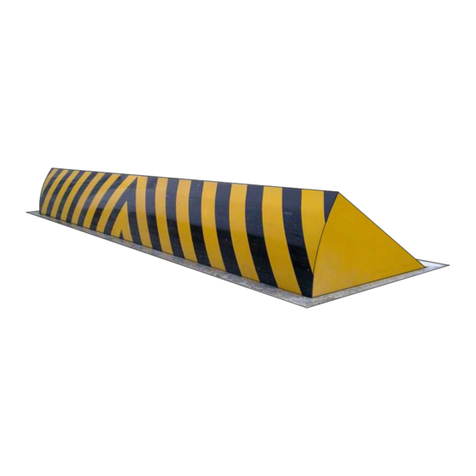
Parking Facilities PF5700 Instruction manual

Parking and access control equipment manufactured in the UK
PF5700 Swing Gate Manual
Rev:1.0
Installation, Operation &
Maintenance Manual
Manual Barriers
Auto Sliding barriers
Auto Bi-Fold barriers
Auto Rising Kerbs
Turnstiles
Auto Rising Bollards

This equipment is part of a large range of traffic flow products. Any of the instructions in this manual should only be carried out
by a qualified service engineer or a competent person.
The following information is a guide only, and whilst we have made every effort to be accurate and correct there may be printing
errors which we cannot be held responsible for.
With a correct installation you can expect to enjoy many years of reliable service from this product, we do however recommend
that the product has a bi-annual service carried out by a qualified engineer.
Thank you for your custom and welcome to the exciting world of Total Traffic Flow Solutions.
/ /20
!
Important Safety Notice
Manual Swing Gates are designed to Control the flow of
vehicular traffic only. It can be dangerous to allow the passage of
pedestrians and any other self-powered animal or device to
utilise this method of access.
It may be necessary for the end user of this product to provide
an alternative, safe method of access to cater for the previously
mentioned categories.
The end user should fit all necessary signage and warning
notices to either side of the gate, which should be visible and
clear from all directions of approach.
Please sign and date below to say that you have read and
understood this notice before ANY installation work:
The “Warnings” leaflet and “Instruction booklet” supplied with this
product should be read carefully as they provide important information
about safety, installation, use and maintenance.
Scrap packing materials (plastic, cardboard, polystyrene etc) according
to the provisions set out by current standards. Keep nylon or polystyrene
bags out of children's reach.
Keep the instructions together with the technical brochure for future
reference.
This product was exclusively designed and manufactured for the use
specified in the present documentation. Any other use not specified in
this documentation could damage the product and be dangerous.
The Company declines all responsibility for any consequences resulting
from improper use of the product, or use which is different from that
expected and specified in the present documentation.
Do not install the product in explosive atmosphere.
The construction components of this product must comply with the
following European Directives: 89/336/CEE, 73/23/EEC, 98/37/EEC
and subsequent amendments. As for all non-EEC countries, the abovementioned
standards as well as the current national standards should
be respected in order to achieve a good safety level.
Information on using
this manual
ŸRead all information thoroughly
ŸPay attention to all safety advice
ŸBe aware of the symbols (shown above right and
above left) as they have different meanings. One is an
information symbol, the other a warning.
ŸThere are many artists impressions of the product in
this manual you should refer to the images as a guide
only. Professional CAD drawings should be used as
a reference drawing and nothing else. As before every
effort has been made to be 100% accurate in this
manual but we cannot make any guarantees.
ŸAs we constantly innovate our products we may
change the quoted spec and any other details that
have been documented in this manual so you should
always refer to the supplier to see if the manual that
was shipped with your product is the latest edition.
ŸAs with all installations, only competent and skilled
personnel should carry out the procedures detailed in
this manual.
ŸBe sure to fill out and complete ALL paperwork where
instructed as this manual is the equipments log book
and maintenance manual.
in Parking and access control equipment manufactured in the UK
Manual Swing Gate

Construction Steel Posts & Frame
Span(s) 2000mm to 6000mm (Single Leaf)
3000mm to 12000mm (Double Leaf)
Height 1000mm
Finish Yellow RAL 1021 (As Standard)
Galvanised (Optional Extra)
Fixing Options Cast-In (As Standard)
Bolt Down
Wall Mounted
Accessories Latch Back Posts (Optional Extra)
Padlock & Keys
Padlock Shroud (Optional Extra)
in Parking and access control equipment manufactured in the UK
Manual Swing Gate

in Parking and access control equipment manufactured in the UK
Manual Swing Gate
SAFETY WARNING:
Before attempting installation of the PF5700 Manual Swing Gate, please ensure that the
information to follow is read and understood. Only competent and skilled personnel should
carry ou any work. This document should be retained for future reference and use.
IMPORTANT INFORMATION:
Any adjustments to the F5700 Manual Swing Gate must be carried out in compliance with
current safety standards.
IMPORTANT INFORMATION:
The PF5700 Manual Swing Gate is designed for the control of motorised vehicles. It is
NOT DESIGNED for pedestrian use or any other use. It is important to ensure an
alternative access route is available for pedestrians and other site users who are not in a
motorised vehicle. Signage is recommended to try and prevent misuse.
Weather conditions may cause the Manual Swing Gate to move if it is not secured
correctly. This could result in serious injury to personnel, vehicles and property. Latch back
posts are highly recommended as a secure way of fixing the gates in the open position.
Parking Facilities Ltd does not accept any responsibility for injury or damage

6
in Parking and access control equipment manufactured in the UK
Swinging Access Gate
Figure 9A : Standard Swing
Arm Barrier Exploded

in Parking and access control equipment manufactured in the UK
Swinging Access Gate
7
Item
ItemItem
Item
Description
DescriptionDescription
Description
01 Barrier Hinge Post
02 Barrier Leaf
03 Closing Post
04 M20 x 120 Hex Hd. Bolt
05 Washer
06 Hex Nut
07 Eye Bolt/ Hinge
08 M8 x 40 Hex Hd. Screw
09 M8 Washer
10 M8 Nyloc Nut
11 Neoprene
12 Latch
13 Padlock & Keys

in Parking and access control equipment manufactured in the UK
Swinging Access Gate
8
METHOD STATEMENT
MAINTENANCE OF A SWING ARM
BARRIER
1. Obtain a Work Permit.
2. Cordon off area as required. (using Warning Signs)
3. Wear Personal Protective Equipment as and when required. ( Hard Hat, Safety Glasses,
High Vis Jackets, Gloves , Safety Boots)
4. Inspect barrier for damage.
5. Ensure hinge mechanism is free from contaminants.
6. Check the locking mechanism for serviceability.
7. Check the Hand-wind handle for ease of operation.
8. Ensure all post holding down bolts, are secure and are tight.
9. Check operation of the barrier and ensure barrier locks in open and closed positions.
10. Wipe down and clean barrier.
11. Remove cordoned off area
12. Depart the site leaving the area clean and tidy.

in Parking and access control equipment manufactured in the UK
Swinging Access Gate
9
HAZARDS WHICH CAN BE FORESEEN:
HAZARDS WHICH CAN BE FORESEEN:HAZARDS WHICH CAN BE FORESEEN:
HAZARDS WHICH CAN BE FORESEEN:
1. Tripping hazards e.g. cables, extension leads, stored materials on site
2. Injuries due to lifting heavy objects.
3. Contact with hazardous substances
4. Electric shock
5. Fire
6. Oncoming vehicular traffic
7. Other Contractors working nearby.
8. Pedestrians
9. Hand entrapment.
CONTROLS IN PLACE TO MINIMISE THE RISK:
CONTROLS IN PLACE TO MINIMISE THE RISK:CONTROLS IN PLACE TO MINIMISE THE RISK:
CONTROLS IN PLACE TO MINIMISE THE RISK:
1. Operators trained and conversant with the mechanics of the barrier operating system.
2. Correct Manual Handling Training techniques to be adhered to at all times.
3. Care is to be exercised to reduce tripping hazards. eg. Removing such hazards away
from the working area.
4. Working area to be cordoned off prior to commencing work.
5. Operators to wear Hi Vis Coats/Waistcoats/Waterproofs.
6. PPE to be worn as and when required and in line with our policy.
(Hard Hat, Safety Glasses, High Vis Jackets, Gloves, Safety Boots)
7. COSHH Regulations to be observed at all times.
8. All electrical power is to be isolated at supply, and checked with a multimeter to ensure
it is switched off before proceeding with the work.
10. Operatives are to be made aware of the clients Health and Safety Procedure and
Emergency Action Plan.
LUBRICATION
The Swing Arm Barrier is a very robust unit and has been designed for minimal
maintenance. The only points requiring lubrication are two-rod eye bearings/ Hinge
assemblies, which will only need a check every 6 months and re-lubricate with a good
quality grease through the nipples provided.

10
in Parking and access control equipment manufactured in the UK
Swinging Access Gate
OPERATION
9.1.
9.1.9.1.
9.1. STANDARD OPERATION OF
STANDARD OPERATION OF STANDARD OPERATION OF
STANDARD OPERATION OF SWING ARM
BARRIER
IMPORTANT INFORMATION
IMPORTANT INFORMATIONIMPORTANT INFORMATION
IMPORTANT INFORMATION:
::
:
The following procedure outlines the safe operation of a swing arm
barrier; these measures should be incorporated into the owner’s on-site risk
assessment.
It is recommended that all operators undergo manual handling training before
attempting to operate the barrier manually.
9.1.1.
9.1.1.9.1.1.
9.1.1. BEFORE OPERATING
BEFORE OPERATINGBEFORE OPERATING
BEFORE OPERATING
i. Vicinity of barrier must be first cleared of all possible obstacles or hazards.
ii. Site should be checked to ensure no vehicles/ pedestrians are within vicinity of
barrier and any present are made aware the barrier will be operating.
9.1.2.
9.1.2.9.1.2.
9.1.2. OPERATION
OPERATIONOPERATION
OPERATION
i. Whilst holding the barrier leaf to retain control of the barrier; unlock and release the
barrier leaf from the close post.
ii. Steadily open the barrier, retaining a firm grip at all times.
iii. Secure in the catch post and lock.
9.1.3.
9.1.3.9.1.3.
9.1.3. AFTER OPERATING
AFTER OPERATINGAFTER OPERATING
AFTER OPERATING
i. Only once fully opened and securely locked into position should users be permitted
access/ egress.
IMPORTANT NOTE:
IMPORTANT NOTE:IMPORTANT NOTE:
IMPORTANT NOTE:
Strong winds may be able to move a gate that has not been properly secured.
Failure to secure the Swing Arm Barrier could result in a serious injury to personnel
or damage to property

in Parking and access control equipment manufactured in the UK
Swinging Access Gate
11
MECHANICAL ADJUSTMENTS
HINGE ADJUSTMENT
The position of the barrier leaf may be adjusted via the barrier
hinges. Though different types of hinges are utilised between
the standard and heavy duty barriers, both are held and
adjusted by two nuts; these nuts are openly accessible on a
standard barrier leaf on the
vertical stanchion.
On the heavy duty barriers these
nuts are located on the hinge
post with one mounted externally
and the other internally; to
access the internal nut you must
first remove the cover plate on
the side of the barrier hinge post,
once inside the hinge may be adjusted in exactly the same
fashion as the standard barriers.
COMMISSIONING
It is preferable that both the installation and commissioning take place when expected through
traffic is at a minimum to avoid disruption.
SAFETY NOTICE:
SAFETY NOTICE:SAFETY NOTICE:
SAFETY NOTICE:
DO NOT place your hands/ fingers inside the barrier when operating
Figure 4: Hinge Adjustment

12
in Parking and access control equipment manufactured in the UK
Swinging Access Gate
BB
BARRIER
ARRIER
For ease of transportation, posts and barrier are despatched separately and should be
erected individually starting with the main barrier hinge post.
Steel packing pieces of various thicknesses should be available to place under the base
plate for levelling purposes. Check that the post is dimensionally positioned correctly with
reference to its closing post, which should be erected in a similar manner. (In the case of a
pair of barriers, check the centre distance between both posts). Ensure that all posts are
vertical before final bolting down.
Barrier Post
::
:
Using a 16mm heavy duty masonry drill bit in a suitable percussion drill, drill through the
four base plate holes to a depth of 180mm taking care to keep the hole free from
excessive dust. The 16mm x 160 long expansion bolts can now be hammered into the
prepared holes, keeping the nuts in the extreme upper position.
Closee//
Catch Posts::
:
Using a 12 mm heavy duty masonry drill bit in a suitable percussion drill, drill through the
four base plate holes to a depth of 170mm taking care to keep the hole free from
excessive dust. The M12 mm x 150 long expansion bolts can now be hammered into
the prepared holes, keeping the nuts in the extreme upper position. Tighten down all
foundation bolts
Barrier Leaf:
Suspend the barrier in a vertical attitude from the crane, or forklift truck, and lower the
barrier into position locating the hinge pins into their hinges.
Once the barrier has been suspended on its hinges, it is necessary to check it for being
horizontal by using a spirit level on the top rail. Any corrections can be carried out at this
stage, both in the open and closed position by careful adjustments to the packing under
the support post base plate, or adjusting the rod eye hinge bearings.
IMPORTANT NOTE:
Ensure that the barrier is safely supported whilst this is being carried out. Once
satisfied that the barrier is hanging correctly, float self-levelling grouting material
under the base plate and finally backfill the foundation cavity with concrete to the
finished road or footpath level as required. If felt desirable, the concrete can be left
50mm below finished level and topped with tarmac or similar to match existing
surface.

in Parking and access control equipment manufactured in the UK
Swinging Access Gate
13
INSTALLATIONINSTALLATION
FOUNDATION
If details of the base have not
been specified, we recommend
a concrete mix to BS EN 206-
1:2000 “Concrete specification,
Performance, Production and
Conformity” to type C32/40,
which is equally suitable for
external and internal
environments. Alternative types
of base construction may be
acceptable, subject to
discussions with our Contract
Engineering Department. It is
not
notnot
not necessary to pre-drill the
base to receive the equipment;
the drilling is carried out when
the equipment is erected. We
recommend a minimum of 7 to
10 days for the concrete to cure,
depending on climate. This time
can be reduced if additive
agents are used.
IMPORTANT NOTE:
IMPORTANT NOTE:IMPORTANT NOTE:
IMPORTANT NOTE:
All bases must be at the same level.
Careful consideration should be made when deciding the location of the barrier to
avoid obstructions such as power cables, telephone cables, trees and similar likely
constructions.
Accessibility around the whole of the barrier should be maintained to a minimum of
1000mm to allow sufficient room for installation, subsequent maintenance and
operation.
IMPORTANT NOTE:
IMPORTANT NOTE:IMPORTANT NOTE:
IMPORTANT NOTE:
PFL should be consulted immediately should any possible restrictions occur
Figure 3 - Foundation Detail

in Parking and access control equipment manufactured in the UK
Swinging Access Gate
Troubleshooting Guide (Mechanical)
Please note these are things that you should look out for with the equipment that has been installed on
your/your customers site. This is in no way a health and safety guide just a few key areas for you to be
aware of and possibly make future changes to.
Plan view (from above)
Sketch system layout, detailing and numbering potential hazard areas for the client.
Potential Hazard Areas - see diagram:
1.................................................................................................................................................................
2.................................................................................................................................................................
3.................................................................................................................................................................
4.................................................................................................................................................................
5.................................................................................................................................................................
Additional Comments / Descriptions concerning safety on this site
................................................................................................................................................................
................................................................................................................................................................
................................................................................................................................................................
................................................................................................................................................................
..................................................................................Signed:.................................................................... 18

System Operation - The user FULLY understands
YES
NO
How to operate the system with all control devices
How to isolate the power to the automation system
How to manually release the system in event of power failure
The safety rules and issues associated with your system
Safety devices on the system have been verified and checked
Safety devices and features suit the site/application for which it was designed
How to open the door on the equipment
Check the following items
YES
NO
Door keys have been handed over
Key switch keys have been handed over
All equipment and site has been left in a clean and safe state
Any warning signage has been fitted by Engineer/Client to make people aware
Any times and special programming instructions undertaken
Product works the way site need it to this includes “no passage time out” etc
System has had the completed conformity certificate
All items on the delivery note have been handed over to client/site -
this should be signed for on the separate sheet which is titled “Delivery Note” (green/ or yellow paper) if parts missing call supplier
The engineer has expressed the importance of regularly maintaining the equipment
POWER ISOLATION - The power isolator for your automation system is located at:
.....................................................................................................................................................
The following denotes that the above has been completed to a satisfactory standard. The engineer has explained the system of
operation to you and any devices that you have had fitted. If this is agreed and has been displayed please sign in the indicated
fields below. All information will be passed on correctly to other system users. The users of the system will use this system
correctly and safely.
Engineers Name: ........................................................................ Engineers Signature: ...........................................
Clients Name: ............................................................................. Clients Signature: .................................................
in Parking and access control equipment manufactured in the UK
Swinging Access Gate
Installation/Commissioning Check List
19

Date
Reason for visit/Action taken
Engineers Signature
/ /20
/ /20
/ /20
/ /20
/ /20
/ /20
/ /20
/ /20
/ /20
/ /20
/ /20
/ /20
/ /20
/ /20
/ /20
/ /20
/ /20
/ /20
/ /20
/ /20
/ /20
/ /20
This Manual must be completed in accordance with the guidelines below, at any point service/repair work is
carried out on the product. This is to achieve two things;
1. To keep a history of the product for yourself and your supplier/manufacturer.
2. To keep an accurate log of any historical or recent modifications, and/or problems, to help an engineer in
the event of any future work required on the product.
!
in Parking and access control equipment manufactured in the UK
Swinging Access Gate
Service Log
20

We certify that the system covered by this certificate has been commissioned satisfactorily.
Contract Reference
Contract Title
Installation Commenced
/ /20
Completion
Engineers Installing
Commissioning
Works Description
Part/Whole Certificate
Handover Date
Part 3.The system(s) designed and installed in accordance with the following documents:
Document Ref:
Revision
Description
PF9500A O&M
5.0
System guides and drawings as defined within O&M Manuals
Part 4.The following test procedures refer:
Check Lists (pages 15 & 16) /Commissioning Certificate
Part 5. Existing Installation Items not covered under warranty/ This certificate:
Installers Name
On Behalf of
Address
Signature
Date of Signing
Position
Parts Handed Over
Qty:
Part 6. Certificate Signing off Section
Client Name
On Behalf of
Address
Signature
Date of Signing
Position
Parts Handed over
Qty:
in Parking and access control equipment manufactured in the UK
Swinging Access Gate
Commissioning Certificate

The machinery which this declaration refers to, is in accordance
with the conditions of the following directives;
Machinery Directive 2006/42/EC.
Low Voltage Directive 2006/42/EC.
Electromagnetic Compatibility Directive 2006/42/EC.
And is in conformity with the following standards & other specifications;
EN292-1 1991 Machinery basis terminology & methodology.
EN292-2 machinery technical principles & specification.
EN6100-6-3 Electromagnetic compatibility – Immunity generic standard
residential, commercial and Heavy Industry.
Made in the UK
Company Representative from manufacturer:
Name: Anthony Green
Position: Managing Director
PF Ltd
Unit One, Kingsbury Link
Trinity Road, Tamworth
Staffs, B78 2EX
Date of Declaration: 01/04/2010
Person Authorised to compile file:
Name: Damian Speer
PF Ltd
Position: Service & Technical Team
Company Installing who is established in the community
Complete below:
Name:
Equipment Serial Number and date of manufacturer of this equipment is affixed net on a white CE sticker
in Parking and access control equipment manufactured in the UK
Swinging Access Gate
Certificate of Conformity
23

GB
2003/108/CE Directive
for waste electrical and
electronic Equipments
DISPOSE OF PROPERLY
ENVIRONMENT - NOXIOUS MATERIALS
EUROPEAN MARK CERTIFYING CONFORMITY
TO THE ESSENTIAL REQUIREMENTS OF THE
STANDARDS 2006/42/EC
Proudly Proudly MadeMade
in the UK in the UK
Proudly Made
Made using
recycled
paper
in Parking and access control equipment manufactured in the UK
Swinging Access Gate
Table of contents
Other Parking Facilities Control System manuals