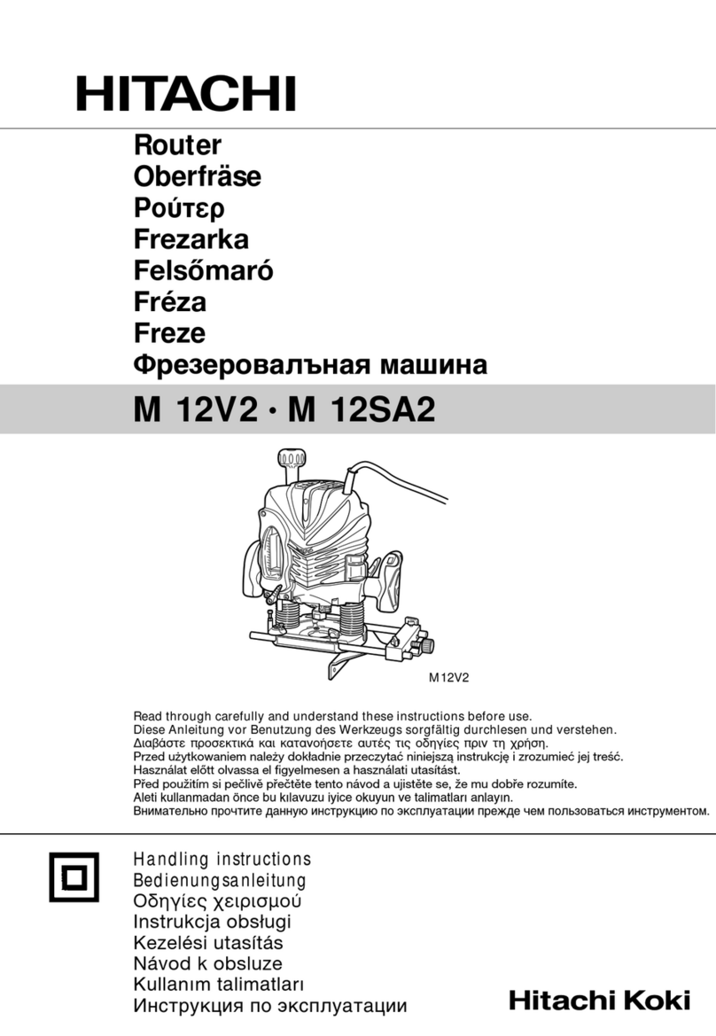
Festool OF 1010 REQ-F User manual

en Original instructions - Router 6
fr Notice d'utilisation d'origine - Défonceuse 17
es Instrucciones de uso originales - Fresadora 30
Read all instructions before using
Lire toutes les instructions avant de démarrer les travaux.
Lea y comprende todas las instrucciones antes de usar.
OF 1010 REQ-F
Festool GmbH
Wertstraße 20
73240 Wendlingen
Germany
www.festoolusa.com
722366_C / 2021-09-20


1-1
1-2
1-3
1-4
1-5
1-6
1-16
1-15
1-14
1-13
1-12
1-11
1-10
1-9
1-8
1-7
1min-1
1 ~
9 500
2 ~ 12 000
3 ~ 14 600
4 ~ 17 200
5 ~ 19 900
6 ~ 23 000
4
5


Contents
1 About this manual....................................... 6
2 Symbols.......................................................6
3 Safety warnings...........................................6
4 Intended use................................................9
5 Technical data............................................. 9
6 Functional description................................ 9
7 Commissioning........................................... 9
8 Settings......................................................10
9 Working with the electric power tool........12
10 Service and maintenance..........................15
11 Accessories............................................... 15
12 Environment..............................................16
1 About this manual
Save these instructions
It is important for you to read and understand
this manual. The information it contains relates
to protecting your safety and preventing prob
lems. The symbols below are used to help you
recognize this information.
DANGER Description of imminent
hazard and failure to avoid
hazard will result in death.
WARN
ING
Description of hazard and
possible resulting injures
or death.
CAUTION Description of hazard and
possible resulting injuries.
NOTICE Description of possible
damage of the device or its
surroundings.
2 Symbols
Warning of general danger
Warning of electric shock
Read the operating instructions and
safety instructions.
Wear ear protection.
Wear protective gloves when changing
tools and working with raw materials.
Wear a dust mask.
Wear protective goggles.
Pull out the mains plug
Safety class II
Tip or advice
Handling instruction
Disconnecting the mains power cable
Connecting the mains power cable
V Volt
A Ampere
Hz Hertz
W Watt
~ Alternating current
n0no load speed
rpm
min-1
tr/mn
revolutions per minute
kg kilogram
lb. pound
" Inch
mm millimetre
3 Safety warnings
3.1 General power tool safety warnings
WARNING! Read all safety warnings, in
structions, illustrations and specifica
tions provided with this power tool. Failure to
follow all instructions listed below may result in
electric shock, fire and/or serious injury.
Save all warnings and instructions for future
reference.
The term "power tool" in the warnings refers to
your mains-operated (corded) power tool or
battery-operated (cordless) power tool.
1 WORK AREA SAFETY
a. Keep work area clean and well lit. Clut
tered or dark areas invite accidents.
b. Do not operate power tools in explosive
atmospheres, such as in the presence of
flammable liquids, gases or dust. Power
tools create sparks which may ignite the
dust or fumes.
English
6

c. Keep children and bystanders away while
operating a power tool. Distractions can
cause you to lose control.
2 ELECTRICAL SAFETY
a. Power tool plugs must match the outlet.
Never modify the plug in any way. Do not
use any adapter plugs with earthed
(grounded) power tools. Unmodified plugs
and matching outlets will reduce risk of
electric shock.
b. Avoid body contact with earthed or
grounded surfaces, such as pipes, radia
tors, ranges and refrigerators. There is an
increased risk of electric shock if your body
is earthed or grounded.
c. Do not expose power tools to rain or wet
conditions. Water entering a power tool will
increase the risk of electric shock.
d. Do not abuse the cord. Never use the cord
for carrying, pulling or unplugging the
power tool. Keep cord away from heat, oil,
sharp edges or moving parts. Damaged or
entangled cords increase the risk of elec
tric shock.
e. When operating a power tool outdoors,
use an extension cord suitable for outdoor
use. Use of a cord suitable for outdoor use
reduces the risk of electric shock.
f. If operating a power tool in a damp loca
tion is unavoidable, use a residual current
device (RCD) protected supply. Use of an
RCD reduces the risk of electric shock.
3 PERSONAL SAFETY
a. Stay alert, watch what you are doing and
use common sense when operating a pow
er tool. Do not use a power tool while you
are tired or under the influence of drugs,
alcohol or medication. A moment of inat
tention while operating power tools may re
sult in serious personal injury.
b. Use personal protective equipment. Al
ways wear eye protection. Protective
equipment such as a dust mask, non-skid
safety shoes, hard hat or hearing protection
used for appropriate conditions will reduce
personal injuries.
c. Prevent unintentional starting. Ensure the
switch is in the off-position before con
necting to power source and/or battery
pack, picking up or carrying the tool. Car
rying power tools with your finger on the
switch or energising power tools that have
the switch on invites accidents.
d. Remove any adjusting key or wrench be
fore turning the power tool on. A wrench
or a key left attached to a rotating part of
the power tool may result in personal in
jury.
e. Do not overreach. Keep proper footing and
balance at all times. This enables better
control of the power tool in unexpected sit
uations.
f. Dress properly. Do not wear loose cloth
ing or jewellery. Keep your hair and cloth
ing away from moving parts. Loose
clothes, jewellery or long hair can be
caught in moving parts.
g. If devices are provided for the connection
of dust extraction and collection facilities,
ensure these are connected and properly
used. Use of dust collection can reduce
dust-related hazards.
h. Do not let familiarity gained from frequent
use of tools allow you to become compla
cent and ignore tool safety principles. A
careless action can cause severe injury
within a fraction of a second.
4 POWER TOOL USE AND CARE
a. Do not force the power tool. Use the cor
rect power tool for your application. The
correct power tool will do the job better and
safer at the rate for which it was designed.
b. Do not use the power tool if the switch
does not turn it on and off. Any power tool
that cannot be controlled with the switch is
dangerous and must be repaired.
c. Disconnect the plug from the power
source and/or remove the battery pack, if
detachable, from the power tool before
making any adjustments, changing acces
sories, or storing power tools. Such pre
ventive safety measures reduce the risk of
starting the power tool accidentally.
d. Store idle power tools out of the reach of
children and do not allow persons unfami
liar with the power tool or these instruc
tions to operate the power tool. Power
tools are dangerous in the hands of un
trained users.
e. Maintain power tools and accessories.
Check for misalignment or binding of mov
ing parts, breakage of parts and any other
condition that may affect the power tool’s
operation. If damaged, have the power
tool repaired before use. Many accidents
are caused by poorly maintained power
tools.
English
7


f. Keep cutting tools sharp and clean. Prop
erly maintained cutting tools with sharp
cutting edges are less likely to bind and are
easier to control.
g. Use the power tool, accessories and tool
bits etc. in accordance with these instruc
tions, taking into account the working con
ditions and the work to be performed. Use
of the power tool for operations different
from those intended could result in a haz
ardous situation.
h. Keep handles and grasping surfaces dry,
clean and free from oil and grease. Slip
pery handles and grasping surfaces do not
allow for safe handling and control of the
tool in unexpected situations.
5 SERVICE
a. Have your power tool repaired by qualified
specialists only and always use original
spare parts. This ensures that the safety of
the power tool is maintained.
b. Only use original parts for repairs and
maintenance. The use of incompatible ac
cessories or spare parts can result in elec
tric shocks or other injuries.
3.2 Machine-specific safety notices
–Hold the power tool by insulated gripping
surfaces only, because the cutter may
contact its own cord. Cutting a "live" wire
may make exposed metal parts of the pow
er tool "live" and could give the operator an
electric shock.
–Use clamps or another practical way to se
cure and support the workpiece to a stable
platform. Holding the work by your hand or
against the body leaves it unstable and may
lead to loss of control.
–Only cutters provided by Festool for this
purpose may be mounted on the power
tool. The use of other cutters is prohibited
due to the increased risk of injury.
–The maximum rotational speed specified
on the tool must not be exceeded or the
rotational speed range must be observed.
Accessories that rotate faster than the per
missible level can rupture.
–Wait until the power tool has come to a
complete halt before placing it down. The
insertion tool can get caught and lead to a
loss of control of the power tool.
– In the case of materials to be processed
which can become statically charged or
lead to static charging, a dissipative overall
system consisting of an antistatic suction
hose (AS) and extraction mobile must be
used.
– Do not clamp tools with an unsuitable
shank diameter in the clamping collet.
– Only use tools that meet standard
EN 847-1. All Festool routing tools fulfi l
these requirements.
– Ensure that the router bit is seated firmly
and that it runs perfectly.
– The clamping collet and locking nut must
not show any signs of damage
– Do not use cracked or deformed router
bits.
–
Wear suitable personal protective equip
ment: Ear protection, protective goggles,
dust mask for work that generates dust,
protective gloves for working with rough
materials and for changing tools.
3.3 Sawing aluminium
When sawing aluminium, the following meas
ures must be taken for safety reasons:
– Install an upstream residual-current circuit
breaker (RCD, PRCD).
– Connect the power tool to a suitable dust
extractor with an antistatic suction hose.
– Regularly clean dust deposits from the mo
tor housing on the power tool.
– Wear protective goggles.
3.4 Health hazard by dust
WARNING! various dust created by pow
er sanding, sawing, grinding, drilling and
other construction activities contains chemicals
known (to the State of California) to cause can
cer, birth defects or other reproductive harm.
Some examples of these chemicals are:
– lead from lead-based paints,
– crystalline silica from bricks and cement
and other masonry products, and
– arsenic and chromium from chemically
treated lumber.
English
8

The risk from these expo
sures varies, depending on
how often you do this type of
work. To reduce your expo
sure to these chemicals:
work in a well ventilated
area, and work with approved safety equipment,
such as dust masks that are specially designed
to filter out microscopic particles. Wash hands
after handling.
WARNING
TO REDUCE THE RISK OF INJURY, USER
MUST READ INSTRUCTION MANUAL.
4 Intended use
The router is designed for routing wood, plas
tics and wood-based materials.
If the cutters are used for the intended purpose
outlined in the Festool Sales, they may also be
used to machine aluminium and plasterboard.
This power tool may only be used by experts or
instructed persons.
The user is liable for improper or non-in
tended use.
5 Technical data
Router OF 1010 REQ-F
Power input 1010 W
Rated current 8.4 A
Speed 9500 - 23000 min-1
Max. speed (no-load) 26000 min-1
Quick depth adjustment 2-1/8" (55 mm)
Fine depth adjustment 5/16" (8 mm)
Drive shaft connecting
thread
M16 x 1.5
Cutter diameter max. 1-3/8" (35 mm)
Weight as per EPTA
procedure 01:2014:
6.8 lbs. (3.1 kg)
6 Functional description
[1-1] Router table
[1-2] Stepped stop
[1-3] Depth stop
[1-4] Locking for trammel unit
[1-5] Nut
[1-6] Spindle stop
[1-7] Handle/Height adjustment
[1-8] Clamp lever
[1-9] Fine adjuster
[1-10] Depth stop indicator
[1-11] Speed adjusting wheel
[1-12] Locking button
[1-13] Handle
[1-14] On/off switch
[1-15] Extractor connector
[1-16] Grooves for guide bars/parallel side
fence
The pictures for the functional description are
on a fold-out page at the beginning of the in
struction manual. While reading the manual
you can fold out the page for comparison and
quick reference.
Accessories shown or described are not always
included in the scope of delivery.
7 Commissioning
WARNING
Unauthorised voltage or frequency.
Risk of accidents
► The mains voltage and the frequency of the
power source must correspond to the
specifications on the name plate.
► In North America, only Festool machines
with the voltage specifications 120 V/60 Hz
may be used.
CAUTION
Heating of the Plug it connection if bayonet
fitting is not completely locked
Risk of burns
► Before switching on the power tool, make
sure that the bayonet fitting at the mains
cable is closed fully and locked.
► Connect and disconnect the mains power
cable - [2].
English
9

2
7.1 Extension Cord
If an extension cord is required, it must have
sufficient cross-section to prevent an excessive
drop in voltage or overheating. An excessive
drop in voltage reduces the output and can lead
to failure of the motor. The table below shows
you the correct cord diameter as a function of
the cord length for this tool.
Cord Size in A.W.G
Tool`s Ampere Rating Cord Length in Feet
25 50 100 150
3-6 18 16 16 14
6-8 18 16 14 12
8-10 18 16 14 12
10-12 16 16 14 12
12-16 14 12 - -
Wire Sizes in mm2
Tool`s Ampere Rat
ing
Cord Length in Meters
15 30 60 120
3-6 0.75 0.75 1.5 2.5
6-8 0.75 1.0 2.5 4.0
8-10 0.75 1.0 2.5 4.0
10-12 1.0 2.5 4.0 -
12-16 - - - -
Use only NRTL listed extension cords.
Never use two extension cords together. In
stead, use one long one.
The lower the AWG number, the stronger
the cord.
7.2 Switching on/off
The switch [1-14] is an on/off switch (press =
ON, release = OFF).
The on/off switch with the locking button [1-12]
can be engaged to operate in continuous mode.
Press the on/off switch again to release the
lock.
8 Settings
WARNING
Risk of injury, electric shock
► Always disconnect the mains plug from the
socket before performing any work on the
machine.
8.1 Electronics
Speed adjustment
You can continuously adjust the speed within
the speed range using the adjusting
wheel [1-11] (see "Technical data").
This enables you to optimise the cutting speed
to suit each surface.
Materi
al Cutterdiameter Recom
mended
cutter
material
1/8" -
1/2" 5/8" -
1" 1-1/8" -
1-3/8"
3 - 14
mm 15 - 25
mm 26 - 35
mm
Rotary controll setting
Hard
wood 6 - 4 5 - 3 3 - 1 HW (HSS)
Soft
wood 6 - 5 6 - 3 4 - 1 HSS (HW)
Lami
nated
chip
board
6 - 5 6 - 3 4 - 2 HW
Plastic 6 - 4 5 - 3 2 - 1 HW
Alumi
nium 3 - 1 2 - 1 1 HSS (HW)
Plaster
board 2 - 1 1 1 HW
Temperature cut-out
Electronic temperature monitoring is integrat
ed in order to protect against overheating (mo
tor burnout). The safety electronics system
switches off the motor before a critical motor
temperature is reached. Let the machine cool
English
10

down for approximately 3–5 minutes before us
ing it and/or fully loading it again. The cool-
down time is significantly reduced when the
machine is running (no-load).
Restart protection
The built-in restart protection prevents the
power tool from starting up again automatically
if the power is disconnected when the on/off
switch is pressed. In this case, the power tool
must be switched off and then switched back on
again.
Due to the built-in restart protection, the power
tool cannot be switched on and off via an exter
nal switch module.
8.2 Changing tools
CAUTION
Risk of injury from hot and sharp insertion
tool
► Do not use any blunt or faulty insertion
tools.
► Wear protective gloves when handling an
insertion tool.
To change tools, place the power tool on its
side.
Inserting the tool
► Insert the routing tool into the open collet
as far as possible or at least up to the
mark on the router shank.
► Turn the spindle until the spindle stop [1-6]
engages when pressing and the spindle
locks.
► Tighten the nut [1-5] using an open ended
spanner (WAF 19).
Removing the tool
► Turn the spindle until the spindle stop [1-6]
engages when pressing and the spindle
locks.
► Undo the nut [1-5] using an open ended
spanner (WAF 19) until you can feel resist
ance. Overcome the resistance by continu
ing to turn the open ended spanner.
► Remove the router.
8.3 Changing the collets
Collets are available for the following shaft di
ameters: 1/4" (6.35 mm); 5/16" (8 mm) (See
Festool catalogue or online at www.festool.com
for the order numbers)
► Completely unscrew the nut [1-5] and re
move it together with the collet.
► Only insert a new collet into the spindle if a
nut is fitted and engaged.
► Gently screw in the nut. Do not tighten the
nut if no cutter is inserted.
8.4 Setting the routing depth
The routing depth is set in three steps:
1. Set the zero point, see 8.5.
2. Specify the routing depth, see 8.6.
3. Clamp the routing depth, see 8.7.
8.5 Setting the zero point
► Release the clamp lever [1-8] so that the
depth stop [1-3] can move freely.
► Position the router with the router ta
ble [1-1] on a level surface. Open the rotary
knob [1-7] and push the power tool down
wards until the cutter sits on the surface.
► Clamp the power tool in this position by
closing the rotary knob [1-7].
► Press the depth stop [1-3] against one of
the three fixed stops of the rotatable step
ped stop [1-2].
A hex key can be used to individually adjust the
height of each fixed stop.
► Push the indicator [1-10] downwards so
that it points to 0" (0 mm) on the scale.
If the zero position is incorrect, this can be
corrected using the screw on the indica
tor [1-10].
8.6 Specifying the routing depth
The required routing depth can be specified us
ing either quick depth adjustment or fine depth
adjustment.
Quick depth adjustment
► Pull the depth stop [1-3] upwards until the
indicator [1-10] points to the required rout
ing depth.
► Clamp the depth stop in this position using
the clamp lever [1-8].
Fine depth adjustment
► Clamp the depth stop using the clamp lev
er [1-8].
► Set the required routing depth by turning
the adjusting wheel [1-9].
Turning the adjusting wheel by a mark
changes the routing depth by 0.004"
(0.1 mm). A full rotation changes the rout
ing depth by 1/16" (1 mm). The maximum
adjustment range for the adjusting wheel
is 5/16" (8 mm).
English
11

8.7 Clamping the routing depth
► Open the rotary knob [1-7] and push the
power tool down until the depth stop touch
es the fixed stop.
► Clamp the power tool in this position by
closing the rotary knob [1-7].
8.8 Dust extraction
WARNING
Heath hazard posed by dust
► Always work with an extractor.
► Comply with national regulations.
CAUTION! If an anti-static suction hose is not
used, static charge may occur. The user may
receive an electric shock and the electronics of
the power tool may be damaged.
A Festool dust extractor with an extractor hose
diameter of 1-7/16" (36 mm) or 1-1/16" (27 mm)
(1-7/16" (36 mm) recommended due to the re
duced risk of clogging) can be connected to the
extractor connector [1-15].
Chip catcher KSF-OF
KSF-OF chip catcher [3-1] (partly accessory)
consists of a hood and cover and can increase
the efficiency ot the extraction when routing
edges. Installation is similar to that of the copy
ing ring., the cover is attached at the top.
The hood can be cut off along the grooves [3-2]
using a hacksaw and can thus be reduced in
size. The chip catcher can then be used for inte
rior radiuses up to a minimum radius of 1-1/2"
(40 mm).
3-1
3-2
3
9 Working with the electric
power tool
When working on the machine, observe
all of the safety warnings that are listed
at the start as well as the following rules:
– Only guide the power tool towards the
workpiece when it is switched on.
– Always secure the workpiece in such a way
that it cannot move during machining.
– When working, always hold the power tool
with both hands on the handles [1-7] +
[1-13]. This is a prerequisite for precise
work and is essential for plunge-cutting.
Plunge into the workpiece slowly and even
ly.
– When routing, ensure that the power tool's
feed direction is the same as the tool's cut
ting direction, see figure [4].
4
Y4-1
4-2
9.1 Freehand routing
Freehand routing is the method normally used
for lettering or shapes, and for routing edges
using cutters with a guide pin or ring.
9.2 Routing with a parallel side fence
For work running parallel to the workpiece
edge, the supplied parallel side fence [5-4] can
be used.
WARNING
Risk of injury
Upon installation on the wrong side, the
router may touch the parallel side fence.
► Only install the parallel side fence on the
side of the power tool depicted in the im
age [5].
► Clamp the two guide rods [5-7] to the paral
lel side fence using the two rotary
knobs [5-2].
► Insert the guide rods into the grooves of the
router table to the required extent and
clamp them using the rotary knob [5-3].
English
12

5-3
5-2
5-3
5-4
5-2
5-5
5-1
5-6
5-7
5-1
5
This distance can be adjusted faster and more
precisely with the fine precision adjust
ment [5-6] available as an accessory:
► Turn the adjusting screw [5-5] in the plastic
part of the guide.
► Clamp the guide rods with the rotating
knobs [5-1] in the precision adjustment.
► Loosen the rotating knobs [5-2] of the par
allel guide.
► Set the desired distance with the adjusting
screw and retighten the rotating knobs.
For better extraxtion, a special suction
hood is available as an accessory for the
side stop.
9.3 Routing with the FS guide system
The guide system (available as an accessory)
makes it easier to route straight grooves.
► Secure the guide rail adapter [6-4] to the
router table using the guide rods [6-3] of
the parallel side fence.
► Secure the guide rail [6-6] to the workpiece
using fastening clamps [6-7].
Ensure that there is a safety distance X of
(see figure [6]) 7/32" (5 mm) between the
front edge of the guide rail and the cutter,
or the groove.
► Place the guide rail adapter on the guide
rail, as shown in figure [6]. To ensure that
the router stop can be guided without play,
use a screwdriver through the top open
ings [6-5] on the side to adjust the two
guidance jaws.
► Tighten the height-adjustable support [6-2]
on the threaded hole of the router table so
that the underside of the router table is par
allel to the workpiece surface.
X
6-4
6-6
6-5
6-2
6-1
6-3
6-7
6
When working with marking-up lines, the
marks on the platen [6-1] and the scale on the
support [6-2] show the centre axis of the cutter.
For a more precise setting, a fine adjust
ment is available as an accessory for the
guide system.
9.4 Routing with the beam compasses
With the SZ-OF 1000 beam compasses (acces
sory) you can make circular cuts or segments
of circles with diameters from 6-1/32 to 29-7/8"
(153 to 760 mm).
► The beam compasses are pushed into the
front groove of the platen until the desired
radius is set.
► Lock the beam compasses with the rotating
knob [1-4].
To prevent the tip of the compasses
from making a hole in the workpiece,
fix a thin board at the centre point by
means of double-sided adhesive tape.
9.5 Copy cutting
A copying ring or the copying device is used to
exactly reproduce existing workpieces (acces
sories).
English
13

7-1
7-2
7-3
7-57-4 7-6
7-7
7
8-1
8
Copying ring
When choosing the size of the copying
ring [4-1], ensure that the cutter [4-2] being
used fits through its opening.
► Secure the copying ring to the router table
from below in place of the covering
ring [8-1].
Excess Y (figure [4]) of the workpiece to the
template is calculated as follows:
Y = (copying ring diameter - cutter diameter)/2
The copying ring can be exactly centred with the
ZD-OF centring mandrel (accessory).
Copying device
The copying device requires the angle arm WA-
OF [7-2] and the copier scanning set KT-OF,
consisting of a roller support [7-6] and three
copying rollers [7-7].
► Use the rotary knob [7-1] to tighten the an
gle arm to the required height on the
threaded hole [7-3].
► Fit a copying roller to the roller support and
use the rotary knob [7-5] to tighten it on the
angle arm. Make sure that the copying roll
er and the router have the same diameter.
► The distance between the feeler roller and
the cutter axis can be adjusted by turning
the adjusting wheel [7-4].
9.6 Edge band trimming
Protruding edge bands can be flush trimmed
with the angle arm WA-OF [9-2] in connection
with the guide plate UP-OF [9-5] (accessory).
► Screw the angle arm into the platen’s
threaded bore [9-1] with the rotating
knob [9-3].
► Bolt the guide plate to the angle arm with
the rotating knob [9-4].
► Adjust the milling depth so that this is equal
to the thickness of the edge band +1/16"
(2 mm).
► Move the guide plate [10-1] as close as
possible to the cutter by loosening the ro
tating knob [10-3].
► Adjust the depth of the guide plate with the
adjusting wheel [10-2] so that during trim
ming a few decimillimetres of the edge
band are left protruding which can then be
sanded down by hand.
9-1 9-2
9-3
9-4 9-5
9
English
14

10-2 10-3
10-1
10
10 Service and maintenance
WARNING
Any maintenance or repair work that re
quires opening of the motor or gear housing
should only be carried out by an authorised
Customer Service Centre (name supplied by
your dealer)!
► Maintenance or repair work carried out by
an unauthorised person can lead to the
wrong connection of the power cord or oth
er components, which in turn can lead to
accidents with serious consequences.
WARNING
To prevent accidents, always remove the
plug from the power supply socket before
carrying out any changes or maintenance
work on the tool!
► Do not use compressed air to clean the
electrical tool! Do not try to clean parts in
side the tool in this way, as you could let
foreign objects in through the openings of
the tool housing.
CAUTION
Certain cleaning agents and solvents are
harmful to plastic parts.
► Some of these include, but are not limited
to: Gasoline, Acetone, Methyl Ethyl Ketone
(MEK), Carbonyl Chloride, cleaning solu
tions containing Chlorine, Ammonia, and
household cleaners containing Ammonia.
Customer service and repairs must
only be carried out by the manufac
turer or service workshops. Find the
nearest address at:
www.festoolusa.com/service
Always use original Festool spare
parts. Order no. at:
www.festoolusa.com/service
EKAT
1
235
4
The tool is equipped with special self-discon
necting carbon brushes. If they wear out, the
power supply is disconnected automatically and
the tool stops.
Check all warnings on the electric power tool
for readability and completeness. Replace
missing or illegible warnings.
Observe the following instructions:
► Damaged safety devices and components
must be repaired or replaced in a recog
nised specialist workshop, unless otherwise
indicated in the operating instructions.
► To ensure constant air circulation, always
keep the cooling air openings in the housing
clean and free of blockages.
11 Accessories
Use only original Festool accessories and
Festool consumable material intended for this
machine. These components are designed spe
cifically for this machine. Using accessories
and consumable material from other suppliers
will most likely affect the quality of your results
and limit warranty claims. Machine wear or
your own personal workload may increase de
pending on the application. Protect yourself and
your machine, and preserve your warranty
claims by always using original Festool acces
sories and Festool consumable material!
The order numbers of the accessories and tools
can be found in the Festool catalogue or on the
Internet under "www.festoolusa.com".
11.1 SYSTAINER
Systainer
Many Festool products are shipped in a unique
system container, called "Systainer". This pro
vides protection and storage for the tool and ac
cessories. The Systainers are stackable and
can be interlocked together. They also can be
interlocked atop Festool CT dust extractors.
English
15

To open the Systainer
Turn the T-loc [SYS-b-1] to this posi
tion.
To lock the Systainer
Turn the T-loc [SYS-b-1] to this posi
tion.
To connect two Systainers
Place one Systainer on the top of the other
(Fig. [SYS-a]).
Turn the T-loc [SYS-b-1] to one of
this positions (Fig. [SYS-b]).
The Systainers are connected and locked.
A Systainer Classic Line can be connected
to a Systainer T-Loc or to a Systainer3
from below via its four locking devices.
A Systainer T-Loc can be connected to a
Systainer3 both from below and from
above.
SYS-a
SYS-b-1
SYS-b
open
lock
connect
connect
T-loc
12 Environment
Do not dispose of the device as domestic
waste! Dispose of machines, accessories and
packaging at an environmentally responsible
recycling centre. Observe the respective nation
al regulations.
English
16

Sommaire
1 À propos de ce manuel..............................17
2 Symboles................................................... 17
3 Consignes de sécurité...............................18
4 Utilisation conforme..................................20
5 Caractéristiques techniques.....................21
6 Éléments de l'appareil..............................21
7 Mise en service..........................................21
8 Réglages....................................................22
9 Utilisation de l'outil électroportatif...........24
10 Maintenance et entretien..........................27
11 Accessoires............................................... 28
12 Environnement..........................................29
1 À propos de ce manuel
Conservez ces instructions
Il est important pour vous de lire et de com
prendre ce manuel. Les informations qu'il con
tient, se rapporte à la protection de votre sécu
rité et de prévention des problèmes. Les sym
boles suivants sont utilisés pour vous aider à
reconnaître cette information.
DANGER Description du risque immi
nent et l'incapacité à éviter
tout risque qui peut entraî
ner la mort.
AVER
TISSE
MENT
Description des dangers
possibles et des blessures
qui en résultent ou la mort.
ATTEN
TION
Description des dangers et
des éventuelles blessures
qui en résultent.
AVIS Description des dommages
potentiels sur l'appareil ou
dans son environnement.
2 Symboles
Avertit d'un danger général
Avertit d'un risque de décharge électri
que
Lire le mode d'emploi et les consignes
de sécurité !
Porter une protection auditive !
Portez des gants de protection pour
changer de lame et pour manipuler
des matériaux rugueux !
Porter une protection respiratoire !
Porter des lunettes de protection !
Débrancher la fiche secteur
Classe de protection II
Conseil, information
Instruction
Débrancher le câble de raccordement
secteur
Brancher le câble de raccordement
secteur
V Volt
A Ampère
Hz Hertz
W Watt
~ Courant alternatif
n0Vitesse de rotation à vide
rpm
min-1
tr/mn
Tours par minute
kg kilogramme
lb. Livre
" Pouce
mm millimètre
Français
17

3 Consignes de sécurité
3.1 Consignes générales de sécurité pour
outils électroportatifs
AVERTISSEMENT ! Veuillez lire toutes
les consignes de sécurité, instructions,
illustrations et caractéristiques techniques qui
accompagnent le présent outil électroportatif.
Des négligences relatives aux instructions sui
vantes peuvent occasionner un choc électrique,
un incendie et/ou des blessures graves.
Conserver l'ensemble des consignes de sécu
rité et des instructions afin de pouvoir les con
sulter ultérieurement.
Le terme « outil électroportatif » utilisé dans
les consignes de sécurité se rapporte aux outils
électroportatifs fonctionnant sur secteur (avec
câble) et aux outils électroportatifs fonction
nant sur batterie (sans câble).
1 SÉCURITÉ DU POSTE DE TRAVAIL
a. Veillez à ce que la zone de travail soit pro
pre et bien éclairée. Un poste de travail en
désordre ou mal éclairé peut entraîner des
accidents.
b. Ne vous servez pas de l'outil électroporta
tif dans un environnement où il y a un ris
que d'explosion dû à la présence de liqui
des inflammables, de gaz ou de poussiè
res. Les outils électroportatifs peuvent gé
nérer des étincelles susceptibles d'enflam
mer la poussière ou les vapeurs.
c. Éloignez les enfants et d'autres personnes
pendant l'utilisation de l'outil électropor
tatif. Si vous êtes distrait, vous pouvez per
dre le contrôle de l'outil électroportatif.
2 SÉCURITÉ ÉLECTRIQUE
a. Le connecteur de l'outil électroportatif
doit correspondre à la prise électrique. Le
connecteur ne doit être modifié d'aucune
façon. N'utilisez pas d'adaptateur avec des
outils électroportatifs mis à la terre. Des
connecteurs intacts et des prises corres
pondantes diminuent le risque d'un choc
électrique.
b. Évitez tout contact avec des surfaces mi
ses à la terre telles que des tuyaux, chauf
fages, cuisinières et réfrigérateurs. Un
risque élevé de choc électrique existe si vo
tre corps est relié à la terre.
c. Protégez les outils électroportatifs de la
pluie et de l'humidité. L'infiltration d'eau
dans un outil électroportatif augmente le
risque de choc électrique.
d. Ne détournez pas l'utilisation du câble de
raccordement pour porter l'outil électro
portatif, l'accrocher ou pour tirer le con
necteur de la prise. Éloignez le câble de la
chaleur, de l'huile, de bords tranchants ou
de pièces en mouvement. Des câbles de
raccordement endommagés ou enchevê
trés augmentent le risque de choc électri
que.
e. Si vous travaillez avec un outil électropor
tatif à l'extérieur, utilisez uniquement des
rallonges prévues pour l'extérieur. L'utili
sation d'un câble prévu pour l'extérieur di
minue le risque d'un choc électrique.
f. Utilisez un disjoncteur à courant de défaut
quand le fonctionnement de l'outil élec
troportatif en environnement humide ne
peut pas être évité. L'utilisation d'un dis
joncteur à courant de défaut diminue le ris
que d'un choc électrique.
3 SÉCURITÉ DES PERSONNES
a. Soyez attentif à ce que vous faites, faites
preuve de bon sens lorsque vous travail
lez avec l'outil électroportatif. N'utilisez
pas l'outil électroportatif si vous êtes fati
gué ou si vous êtes sous l'influence de
drogues, de l'alcool ou de médicaments.
Un moment d'inattention lors de l'utilisa
tion de l'outil électroportatif peut entraîner
des blessures graves.
b. Portez un équipement de protection indi
viduelle et des lunettes de protection en
permanence. Le port d'un équipement de
protection individuelle tel que masque
contre la poussière, chaussures de sécu
rité antidérapantes, casque ou protection
auditive, en fonction du type et de l'utilisa
tion de l'outil électroportatif, diminue le
risque de blessures.
c. Évitez toute mise en service involontaire.
Assurez-vous que l'outil électroportatif
est déconnecté avant de le raccorder à
l'alimentation électrique et/ou à la batte
rie, avant de le soulever ou de le porter.
Si, en portant l'outil électroportatif, vous
avez le doigt sur l'interrupteur ou si vous
raccordez l'outil électroportatif connecté à
l'alimentation électrique, cela peut entraî
ner des accidents.
d. Retirez les outils de réglage ou les clés
anglaises avant de connecter l'outil élec
troportatif. Un outil ou une clé qui se trou
ve dans une partie de l'outil électroportatif
en rotation peut entraîner des blessures.
Français
18

e. Évitez toute position de travail anormale.
Veillez à maintenir une position stable et
un bon équilibre à tout moment. Vous
pourrez ainsi à tout moment contrôler l'ou
til électroportatif dans des situations inat
tendues.
f. Portez des vêtements adaptés. Ne portez
pas de vêtements amples ou de bijoux.
Éloignez vos cheveux et vos vêtements
des pièces en mouvement. Des vêtements
amples, des bijoux ou des cheveux longs
pourraient se prendre dans les pièces en
mouvement.
g. Si des dispositifs d'aspiration et de récu
pération des poussières peuvent être
montés, raccordez-les et utilisez-les cor
rectement. L'utilisation d'une aspiration
des poussières peut diminuer les dangers
dus aux poussières.
h. Ne vous croyez pas faussement en sécu
rité et n'enfreignez pas les règles de sé
curité destinées aux outils électroporta
tifs, même si vous maîtrisez l'outil élec
troportatif après de multiples utilisations.
Un manque d'attention peut en un quart de
seconde entraîner de graves blessures.
4 UTILISATION ET TRAITEMENT DE L'OUTIL
ÉLECTROPORTATIF
a. Ne surchargez pas l'outil électroportatif.
Utilisez l'outil électroportatif destiné à vo
tre travail. L'outil électroportatif adapté
vous permet de travailler mieux et avec
plus de sécurité dans la plage de puissance
indiquée.
b. N'utilisez aucun outil électroportatif dont
l'interrupteur serait défectueux. Un outil
électroportatif qui ne peut plus être mis en
marche ou arrêté est dangereux et doit
être réparé.
c. Débranchez le connecteur de la prise de
courant et/ou retirez une batterie amovi
ble avant d'effectuer des réglages sur
l'appareil, de remplacer des pièces d'outil
ou de déposer l'outil électroportatif. Cette
mesure de précaution empêche un démar
rage involontaire de l'outil électroportatif.
d. Rangez toujours les outils électroportatifs
inutilisés hors de portée des enfants. Ne
laissez aucune personne à laquelle vous
ne faites pas confiance ou qui n'a pas lu
ces consignes se servir de l'outil électro
portatif. Les outils électroportatifs sont
dangereux lorsqu'ils sont utilisés par des
personnes inexpérimentées.
e. Prenez soin de vos outils électroportatifs
et outils. Vérifiez que les parties mobiles
fonctionnent sans problème, qu'elles ne
coincent pas et qu'il n'y a pas de parties
cassées ou endommagées qui pourraient
entraver le bon fonctionnement de l'outil
électroportatif. Faites réparer les parties
endommagées avant d'utiliser l'outil élec
troportatif. De nombreux accidents sont
dus à un mauvais entretien des outils élec
troportatifs.
f. Maintenez les outils de coupe affûtés et
propres. Des outils de coupe entretenus
avec soin dotés de bords de coupe affûtés
se coincent moins et sont plus faciles à uti
liser.
g. Utilisez l'outil électroportatif, les outils,
etc. en respectant ces instructions. Tenez
compte des conditions de travail et de la
tâche à effectuer. L'utilisation des outils
électroportatifs pour d'autres applications
que celles prévues peut entraîner des situ
ations dangereuses.
h. Veillez à ce que les poignées et surfaces
des poignées soient sèches, propres et
exemptes d'huile ou de graisse. Des poi
gnées et surfaces de poignées glissantes
ne permettent pas une utilisation en toute
sécurité ni un contrôle de l'outil électro
portatif dans des situations imprévues.
5 SERVICE
a. Faites réparer votre outil électroportatif
uniquement par un personnel qualifié ; les
réparations doivent être uniquement ef
fectuées avec des pièces détachées d'ori
gine, afin de garantir la fiabilité de l'outil
électroportatif.
b. Pour la réparation et l'entretien, n'utilisez
que des pièces d'origine. L'utilisation d'ac
cessoires ou de pièces détachées non
adaptés risque de provoquer une électro
cution ou des blessures.
3.2 Consignes de sécurité spécifiques à
l'appareil
–Tenez l'outil électroportatif uniquement
par les parties isolées car la fraise peut
entrer en contact avec son propre câble de
raccordement. Le contact avec un câble
sous tension peut également mettre des
pièces métalliques de l'appareil sous ten
sion et provoquer une décharge électrique.
–Fixez et bloquez la pièce sur un support
stable au moyen de serre-joints ou d'au
tres accessoires. Si vous maintenez la piè
Français
19

ce uniquement avec la main ou la bloquez
uniquement contre votre corps, elle reste
instable, ce qui peut conduire à une perte
de contrôle.
–L'outil électroportatif doit uniquement
être équipé de fraises proposées à cette
fin par Festool. L'utilisation d'autres frai
ses est interdite en raison d'un risque ac
crue de blessures.
–Ne pas dépasser la vitesse de rotation
maximale indiquée sur l'outil monté et
respecter la plage de vitesse. Les acces
soires dont la vitesse de rotation est supé
rieure à la valeur admissible risquent de se
briser ou d'être projetés.
–Attendez que l'outil électroportatif soit
complètement immobilisé avant de le dé
poser. L'outil monté peut s'accrocher et
provoquer une perte de contrôle de l'outil
électroportatif.
– Pour travailler les matériaux qui se char
gent d'électricité statique ou peuvent pro
voquer une accumulation d'électricité stati
que, il est nécessaire d'utiliser un système
global limitant la formation d'électricité
statique. Celui-ci se compose d'un tuyau
d'aspiration antistatique (AS) et d'un aspi
rateur.
– Pour le serrage des outils, utiliser unique
ment le diamètre de tige pour lequel la pin
ce de serrage est conçue.
– Employez exclusivement des outils confor
mes à EN 847-1. Toutes les fraises de Fes
tool remplissent les exigences de ce stan
dard.
– Veiller à bien fixer la fraise et s'assurer
qu'elle fonctionne parfaitement.
– La pince de serrage et l'écrou-raccord ne
doivent présenter aucun dommage.
– L'utilisation de fraises fissurées ou défor
mées est interdite.
–
Portez un équipement de protection indi
viduelle approprié : une protection auditi
ve, des lunettes de protection, un masque
anti-poussière lors des travaux impliquant
un dégagement de poussière et des gants
de protection dans le cas des matériaux ru
gueux et lors du changement d'outil.
3.3 Sciage de l'aluminium
Pour des raisons de sécurité, prenez les mesu
res suivantes en cas de sciage d'aluminium :
– Installer en amont un disjoncteur différen
tiel.
– Raccordez l'outil électroportatif à un aspi
rateur approprié en utilisant un tuyau d'as
piration antistatique.
– Retirez régulièrement les dépôts de pous
sière accumulés dans le carter moteur de
l'outil électroportatif.
– Portez des lunettes de protection !
3.4 La poussière, un risque pour la santé
AVERTISSEMENT! certaines poussières
créées par le ponçage mécanique, le
sciage, le meulage, le perçage et autres activi
tés reliées à la construction contiennent des
substances chimiques connues (dans l’État de
la Californie) comme pouvant causer le cancer,
des anomalies congénitales ou représenter
d’autres dangers pour la reproduction. Voici
quelques exemples de telles substances:
– plomb provenant de peintures à base de
plomb,
– silice cristallisée utilisée dans les briques,
le ciment et autres matériaux de maçonne
rie, et
– arsenic et chrome du bois d’oeuvre traité
avec un produit chimique.
Le risque d’exposition à de
tels produits varie selon la
fréquence à laquelle vous
faites ce genre de travail.
Pour réduire les risques
d’exposition à ces substan
ces chimiques : travaillez dans un endroit adé
quatement ventilé et utilisez un équipement de
sécurité approuvé, tel que masques antipous
sières spécialement conçus pour filtrer les par
ticules microscopiques.
AVERTISSEMENT
POUR RÉDUIRE LE RISQUE DE DOMMAGES,
L'UTILISATEUR DOIT LIRE LE MANUEL
D'INSTRUCTION.
4 Utilisation conforme
La défonceuse est conçue pour le fraisage du
bois, des matières plastiques et des matériaux
similaires au bois.
Il est également possible de travailler l'alumi
nium et les plaques de plâtre en utilisant les
fraises prévues à cette fin indiquées dans les
documents de vente de Festool
Français
20
Table of contents
Languages:
Other Festool Wood Router manuals
Popular Wood Router manuals by other brands

Metabo HPT
Metabo HPT M 12VE Safety instructions and instruction manual

Porter-Cable
Porter-Cable A15149 instruction manual

HOLZMANN MASCHINEN
HOLZMANN MASCHINEN TFM610V operating manual

Makita
Makita RF1100 instruction manual

Porter-Cable
Porter-Cable 893PK instruction manual

Wen
Wen RT1460 instruction manual