FFS Brands Vizu 400 Pass Through Multi Stack User manual
Page 1of 28
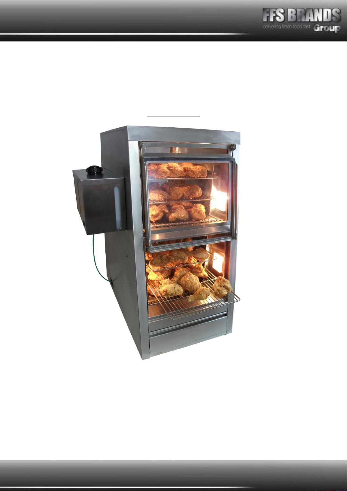
VIZU®400 Pass Through
Multi Stack
VI400PTMS
Counter top ‘Pass Thru’ With a small footprint
Cooked food holding with multi-level racks (multi stack)
Front and rear flap access for quick loading and unloading
Thermostatically controlled environment
Automatic water fill for humid environment
Illuminated interior

Page 2of 28
Contents
VIZU® Multi Stack Pass Thru.........................................................................................1
MULTI STACK PASS-THRU SPECIFICATION PAGE .........................................................3
Model VIMSPT...........................................................................................................3
Assembly and Installation Instructions.........................................................................6
Instructions for use ...................................................................................................7
Description of Multi Stack Auto Fill Pass Thu machines ..................................................8
Use of Auto Fill Pass-Thru machines..........................................................................11
Cleaning of Auto Fill Pass-Thru machines ...................................................................12
Exploded View ........................................................................................................13
Wiring Diagram .......................................................................................................14
Spare Parts List.......................................................................................................15
Cleaning instructions - Daily .....................................................................................19
FAULT FINDING ......................................................................................................20
Terms and Conditions .................................................................................................22
Claims....................................................................................................................22
Returns ..................................................................................................................22
Damage Claim Form ...................................................................................................23
Warranty ...................................................................................................................24
Page 3of 28
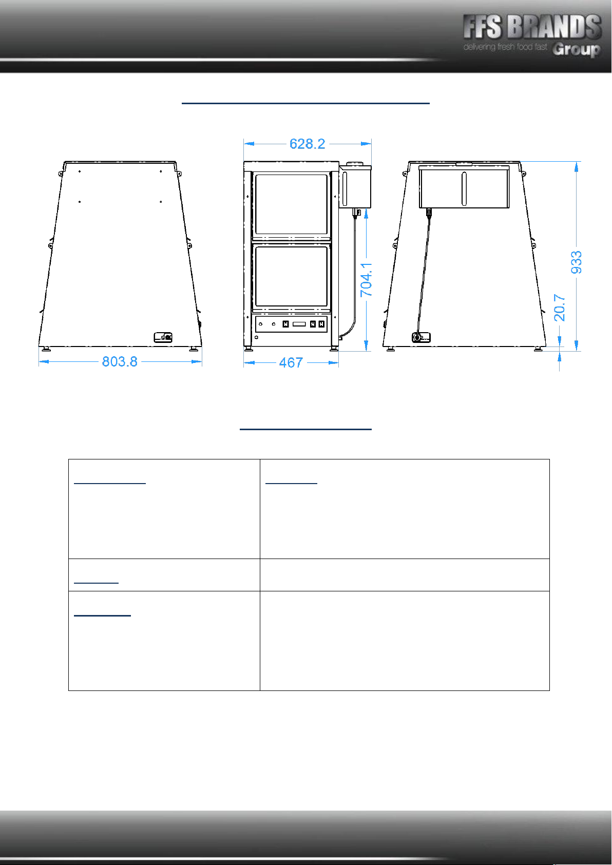
VI400PTMS SPECIFICATION PAGE
Model VI400PTMS
Dimensions
Height
Width
Depth
Machine
935.00 mm
630 / 470 mm
805 mm
Weight
kg
Electrical
Running Amps
Connection Type
International Option
1400w, 1 phase, 50Hz ac
230v, 6 Amps
BSCHUKO 2/3 PIN PLUG
N/A
Page 4of 28
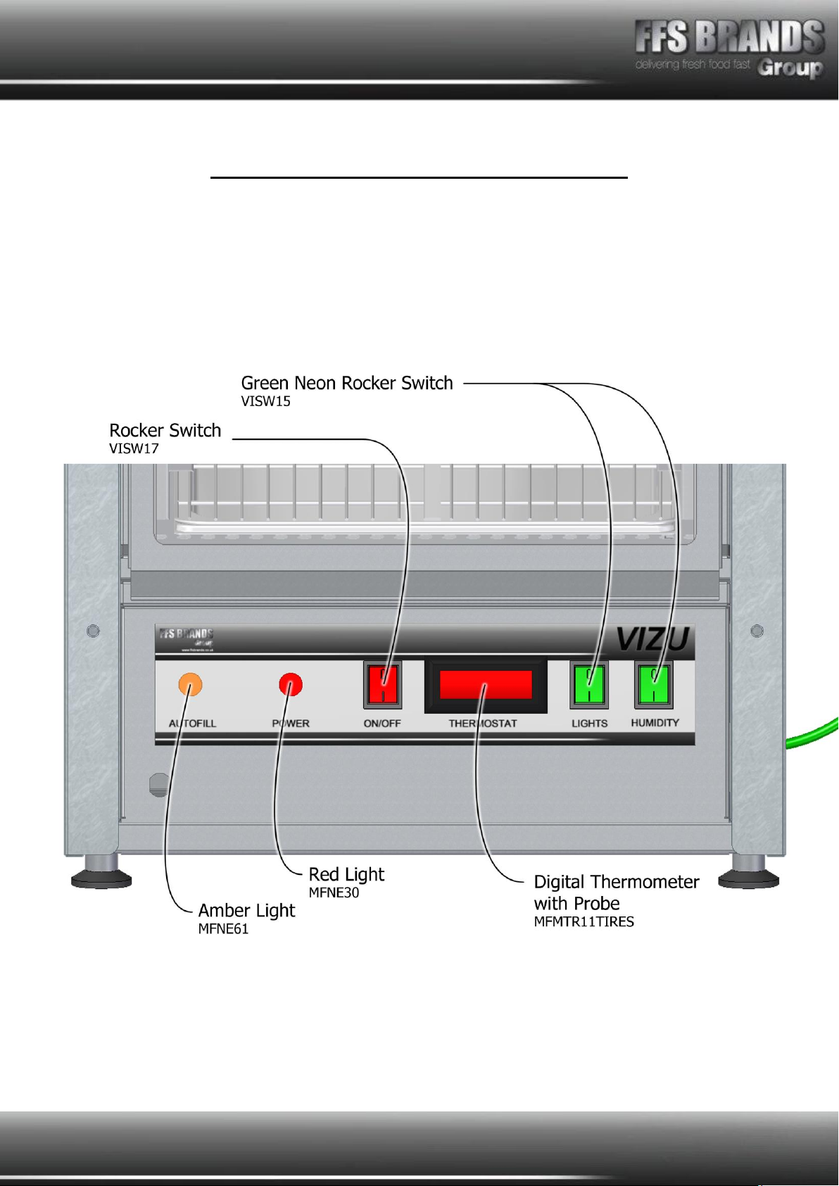
VI400PTMS Control Panel- Labelled Views
The below image shows the individual parts and part names for the ‘Multi Stack
Pass-Thru’ Control Panel situated on the back of the machine. Please refer to this
image for more information regarding the product installation as well as use
instructions.
Page 5of 28

Page 6of 28
All
Vizu 400 Pass Through Multi Stack’s
have been tested and checked for proper
operation before leaving the factory.
Upon delivery please check the unit for damage. If the unit is damaged, contact the carrier,
or Fast Food Systems, immediately and file a damage claim (found in the back of the
manual) Please retain all packing materials.
Damage must be reported within 7 days of delivery
General Description
The unit has been designed to hold cooked foods in a humid atmosphere. Being a pass-thru
unit the machine can be loaded from one side and unloaded from the other.
Assembly and Installation Instructions
1. Unpack machine from packaging
2. Peel all surfaces of plastic film and wipe down with warm soapy water
3. Position machine on a level surface
4. Machine must be affixed to a fresh mains water supply, or side mounted bottle filled
daily with fresh water
5. Machine must be plugged into a 13Amp power supply.
6. Install all removable parts including; Element Cover, Side mounted ‘Rack Supports’,
Gastro Pans and wire racks.
7. Install racking by sliding it into the ‘Rack Supports’
8. Make sure all parts are seated correctly by checking all parts at both sides of the
machine.

Page 7of 28
Switch Controls
Red Switch –‘ON/OFF’
-Controls the temperature within the cabinet via the digital thermostat
Green Switch - ‘LIGHTS’
-Operates the lights within the unit
Green Switch –‘HUMIDITY’
-Operates humidity system within the unit –Can work with main supply or
supplied bottle
Instructions for use
1. Ensure Mains power is on –The red ‘POWER’ light should be lit
2. Ensure either Mains water is on and connected, or the bottle is filled and connected
3. Turn red ‘ON/OFF’ switch to ‘ON’
4. Turn green ‘LIGHTS’and ‘HUMIDITY’ switches to ‘ON’
5. Leave the machine for 20 minutes to heat and humidify
6. Turn on load food as required, from the ‘Control Side’ and unload from the ‘Draw
Side’
7. If using the bottle, please make sure to keep an eye out for the water level in the
bottle.
LED Indication
When the unit is on the red POWER LED indicator with be lit.
When the ON/OFF switch is lit, the unit has power to the heating system, this is
also be indicated by the Digital display being lit
When the GREEN LIGHTS switch is lit, power will be going to the lighting system
When the GREEN HUMIDTY switch is lit, power will be going to the humidity
system
When the AMBER LED indicator is lit, the machine will be filling the internal water
tray to the correct water level

Page 8of 28
Description of Multi Stack Auto Fill Pass Thu machines
The Multi Stack Auto Fill Pass Thru unit must only be used to keep cooked food hot and
moist; it must not be used to re-heat cooked foods.
The machine is suitable for holding cooked meats and fish.
This unit is more complex machine than a standard Pass-Thru and as such there are a few
more rules of use.
When the machine is placed in the position that it will be used in it is important to
ensure that it is level. Ensure that the surface the Pass-Thru is mounted on is flat
and well supported.
The machine can be either connected to a Mains water supply or the supplied water
tank (which must be refilled by the machine operator).
The unit is supplied as standard with the remote water tank. The water pressure
reducing valve is pre-set, however if the location the machine is being installed in
has a different water pressure this may need to be adjusted.
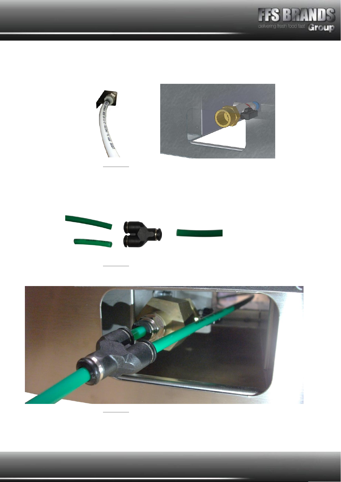
If the tank is to be re-positioned, OR mains feed is to be made the water feed
connection to the machine must be dis-connected. See Fig. 1 & Fig. 2 below.
Figure 1 Figure 2
The standard plumbing fitting used for a washing machine can be fitted to the
remaining threaded piece shown in Fig 2
The tank can be mounted on the opposite side of the unit if desired, alternatively the
tank can be placed on an up-stand or other location –If this is the case it is
important that the tank is NOT at a lower position than it would be if it were
mounted on the side of the machine, otherwise the water flow will be adversely
affected.
Page 9of 28
1. To connect the mains supply, simply screw the mains inlet pipe into the thread on
the fitting, as shown in Fig. 3. Ensure a tight waterproof seal - use PTFE tape.
Figure 3
2. When two VIMSPT’s are next to each other these can be connected together (Only
when using the Bottle), using the Supplied ‘Green Tube’. Cut a piece 1 inch long
(make sure to use a sharp knife to result in a clean cut) and then arrange the parts
as shown in Fig 4.
Figure 4
3. Now connect all the parts together as shown in Fig 5.
Figure 5
Page 10 of 28
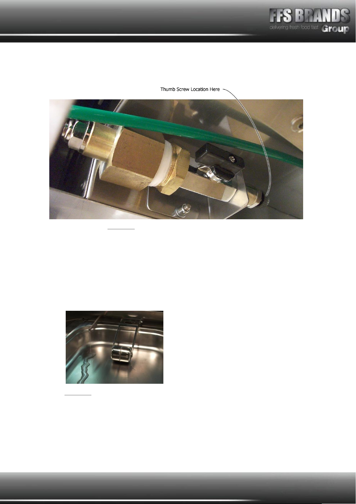
4. When installing the machine to a mains water supply the pressure regulating valve
within the machine must be adjusted to reduce the pressure. This is done by winding
the thumb screw in until the desired pressure is achieved, see Fig. 6.
Figure 6
5. Ensure that the water tray is pushed in to the unit fully (it should lock in position –
pull gently to check). The water filling sequence can now begin. Switch the ‘ON/OFF’
switch for ‘HUMIDITY’ to the ‘ON’ position. The float of the machine will sense that
the water tray is empty and it will begin to fill the machine. (If this does not happen
please check that the draw is fully pushed in (activating the micro-switch) and that
the water supply is connected and able to flow). The amber light on the panel will
light during filling stage, (this is a slow process). The correct pressure should see the
water flow in to the water tray without causing splashing –see Fig 7.
Figure 7
6. It is important that the machine fills slowly so that the water can be heated by the
under pan heater, allowing the machine to fill too quickly will cause the temperature
to drop.
The machine is factory set to 70C. This is adequate to hold cooked food at a safe
and legal temperature (i.e. above 63C)

Page 11 of 28
Use of Auto Fill Pass-Thru machines
1. Switch the machine on (red switch), then switch the auto-fill and lights on (green
switches).
2. The machine should be left for 20 minutes to allow it to reach the correct operating
temperature. By having an automatically filling water system the internal atmosphere
of the unit will be humid, improving the “hold time” that products can be kept for.
3. Whenever the flaps are raised on the Pass Thru unit they should also be lowered in a
controlled manner and not allowed to drop and bang against the side of the
machine. Allowing the flaps to hit the machine can result in damage to the doors but
more importantly weaken the bulbs and reduce their life.
4. Ensure that the water supply is maintained –otherwise the machines humidity will
be affected.
Page 12 of 28
Cleaning of Auto Fill Pass-Thru machines
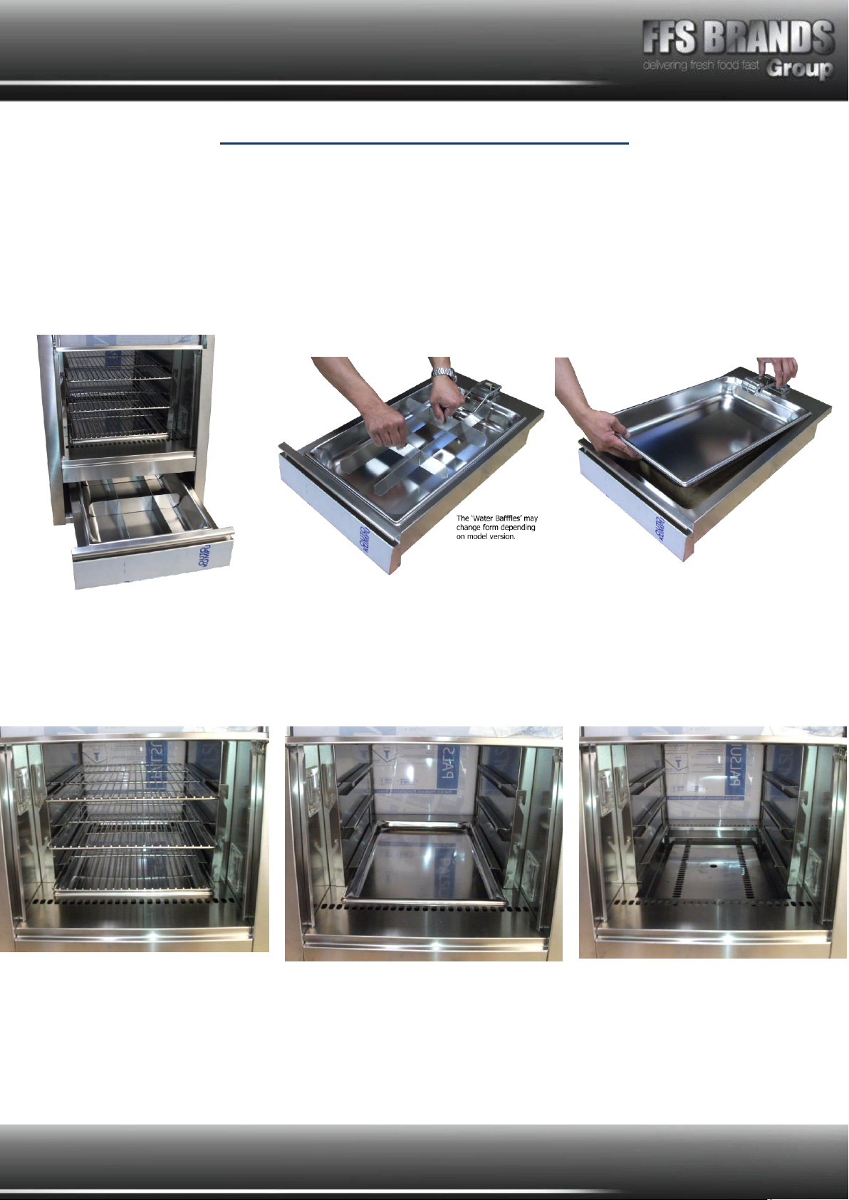
1. The water drawer should be removed daily for cleaning.
TAKE CARE WHEN REMOVING THE WATER DRAWER
Gently lift the front of the water drawer and then slide drawer out of machine, the water will
cut-off automatically when the drawer is removed. Next drain water in to a sink. The water
pan can be removed from the drawer by carefully lifting the float and then removing the pan.
Be careful not to damage float and mechanism.
With the water draw removed the rest of the removable pieces can be removed, Once the
parts have all been removed these can be cleaned in warm soapy water (soak the parts in
warm soapy water if required).
CARE MUST BE TAKEN WHEN CLEANING THE INTERIOR OF THE MACHINE
BECAUSE ELEMENTS, PANELS ETC. MAY REMAIN HOT FOR SOMETIME AFTER THE
HEATING HAS BEEN SWITCHED OFF.

Page 13 of 28
Exploded View
This page can be used as a reference when communicating with FFS Brands Manufacturing
team to help describe parts and locations in the machine.
Page 14 of 28
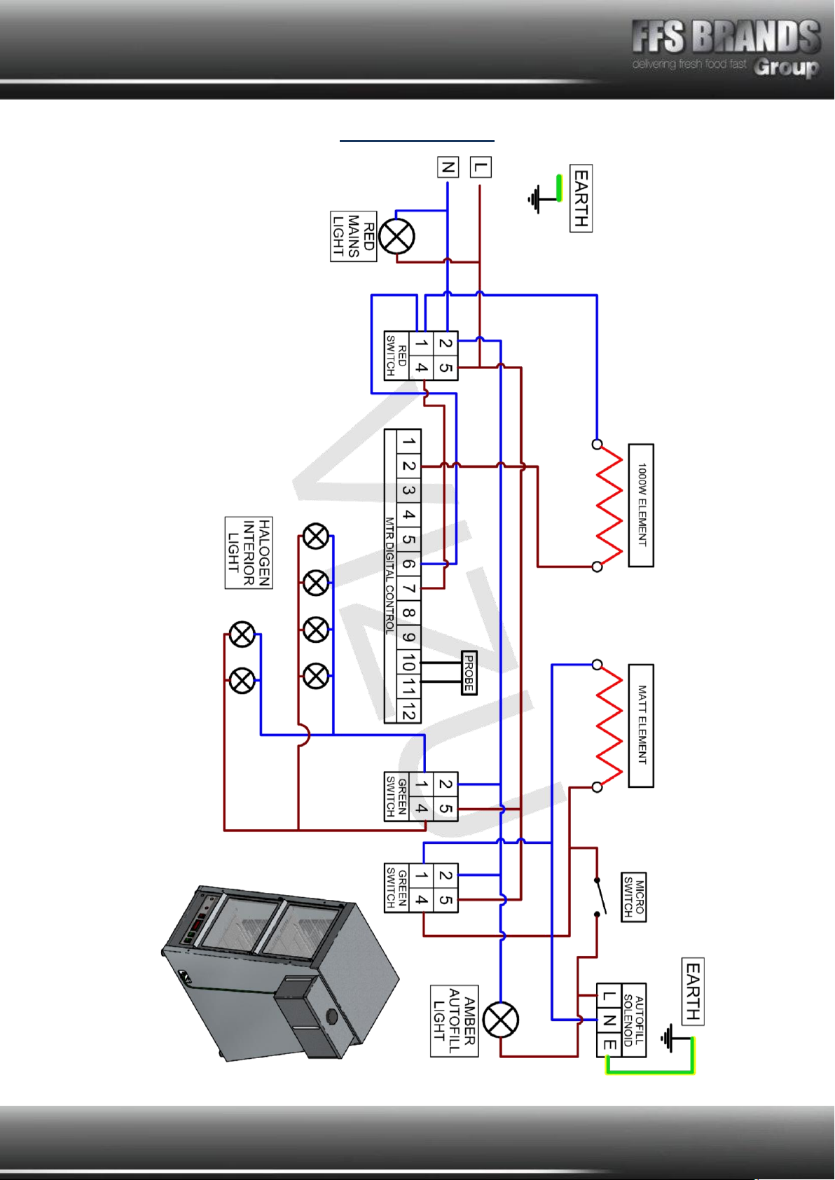
Wiring Diagram
Page 15 of 28
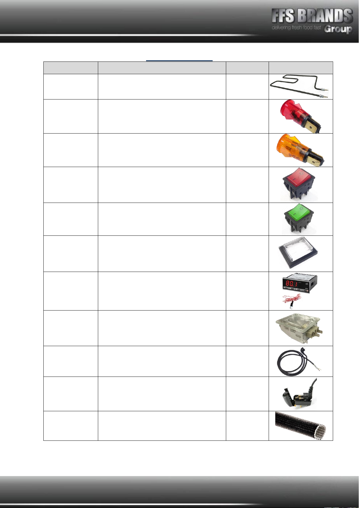
Spare Parts List
PART NO.
PART NAME
QTY.
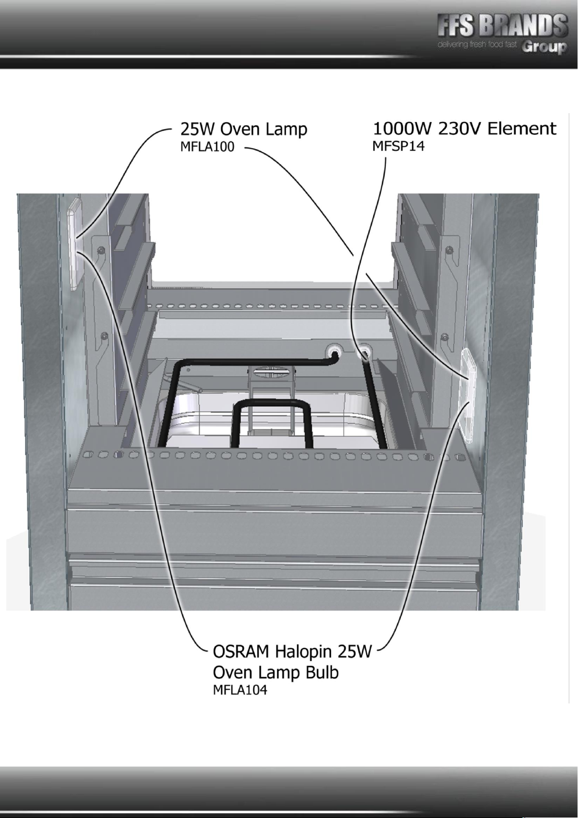
MFSP14
1000W 230V HEATING ELEMENT
1
MFNE30
RED LIGHT
1
MFNE61
AMBER LIGHT
VISW17
ROCKER SWITCH REVOLVA MFC1553ALR
1
VISW15
GREEN NEON ROCKER VIZU
BURGER/PASSTHRU
2
VILE14
SWITCH COVER BEVEL MF1026
3
MFMTR11TIRES
LTR-5TSRE-A(P) DIGI THERM. WITH PROBE
1
MFLA100
OVEN LAMP ASSEMBLY 25W
6
BESCHUKO
H05RR-F 2MTR RUBBER C032
1
MFEUROCONVERT
EURO TO UK CONVERTER PLUG BLACK 19-1032
1
MFOHSL01
HIGH TEMPERATURE SLEEVING
0.8

Page 16 of 28
PART NO.
PART NAME
QTY.
MFLA104
HALOPIN OSRAM OVEN 25W 230V G9
6
MF285-100
FLAP WINDOW 375mm wide x 5mm deep x 321mm
high
4
MF285-101
FLAP RUBBER
4
C07911/100
GN 1/1 GRID / SHELF STAINLESS
6
GSGAST90002
1/1 GASTRONORM PAN - 20mm DEEP
2
GSGAST?????
GASTRONORM PAN 1/4 65mm DEEP
1
MF51LHSPRING
LH TORSION SPRING (PLATED PIANO WIRE)
2
MF51RHSPRING
RH TORSION SPRING (PLATED PIANO WIRE)
2
MF817-8877
NYLON STRAIGHT RELIEF CABLE BUSH
1
MF354Z
2 POLE 5 AMP TERM BLOCK
3
MFFFR12/04
BRASS F-F ADAPTER 3-4 BASPT 1-4 BSPT
1

Page 17 of 28
PART NO.
PART NAME
QTY.
MFRC12/04
BRASS M-M ADAPTER 3-4 BSPT –1-4 BSPT
2
MFVM04
Mini Ball Valve 1/4'' Bspp Brass
2
MFMCU7061/4
Mcu706 1/4 Flow Control
1
MF20231/4-1/4
2023 1/4''-1/4'' Flow Control Concection Ring
1
MFF4PB6-1/4
Union (Male) Bspp
3
MFPU22001-
230V1/8
1/8A Solenoid Valve With Coil
1
MFWADE-
ME106/083
6MMx1/8 Bspt Male Stud Elbow 20X20X10MM
2
MF51FLOAT
Magnetic Float Switch S/S Floating Ball
1
MF515-767
Microswitch Used On Float VI1100/700PT
1
MF12LTRTANKQTR
OUT
12L Tank With 1/4Bsp Female 150X420X200
1

Page 18 of 28
PART NO.
PART NAME
QTY.
MFLTR035G04S
180 Degree S/S Torsion Spring
1
MF483-4964a
Green Standard Nylon Tube 30m x 6mm
1.5 + 0.8
MF605-649
Grommet
2
MF55310-6
6mm push fit plastic y connector
1
MF225WELEMENT
225W mat element 0.75Amps 0.225Kw 230V
1
MF0A074
TONG STORE CLIP LOCK ASSY
4

Page 19 of 28
Cleaning instructions - Daily
1. Disconnect the machine from the power supply before cleaning and allow to cool.
2. Remove food as well as gastronorme pans and wire racks, wash thoroughly in warm
soapy water, rinse and dry.
3. Remove the side racks and wash in warm soapy water, rinse and dry.
4. Remove the element cover and wash in warm soapy water, rinse and dry
5. Doors may be wiped with a soft damp cloth, dry thoroughly taking care not to
damage the plastic.
6. Remove the water tray assembly, lift the float and take out water gastronome plan
and clean thoroughly, (take care not to damage float assembly).
NEVER use wire wool, scourers, abrasive cleaners, acids or bleach.
DO NOT flood or allow electrical parts to become wet.
NEVER handle the lamps; if they become dirty they should be wiped with a soft, damp,
grease free cloth.
DO Dry all surfaces thoroughly removing all moisture.
A stainless steel cleaner/polish may be applied to the exterior.
N.B - For Hard Water Areas
To avoid the risk of scale build up, we advise to either fit an in-line softener if using the
mains supply or use a water softener. If the unit is being used with a remote water tank,
use de-ionised water.
Please be aware of these guidelines as scale is not covered by our warranty, as noted earlier
in this manual

Page 20 of 28
FAULT FINDING
Any servicing must only be carried out by qualified personnel. Unit must be removed from
electrical supply before servicing.
Problem
Probable Cause
Solution
1. Indicated ON/OFF
switch does not light
up
No power to machine.
ON/OFF switch faulty
Check machine is plugged in and switched
on.
Check fuse in 13a plug, replace if faulty.
Check circuit breaker at main supply board
is in (ON) position.
Check Switch, replace if faulty.
2. Digital thermostat
does not indicate
temperature reading.
ON/Off switch OFF
Unit overheated
ON/OFF switch faulty
Digital thermostat faulty
Switch ON
Allow to cool.
Replace switch
Replace if thermostat faulty
3. Lamps do not work
No power
Green switch OFF
Lamp not correctly seated.
Faulty lamp
See section 1
Switch ON Red switch
Switch ON Green switch.
Check fitted correctly
Replace lamp/bulb
4. Unit does not heat
up.
No power to machine
ON / OFF switch OFF
ON / OFF switch faulty
Digital thermostat faulty
Thermocouple faulty
Switching relay faulty
Heat element faulty
See section 1.
Switch ON
Replace Switch
Replace thermostat
As indicated on controller replace
thermocouple
Replace relay
Replace element
This manual suits for next models
1
Table of contents
Other FFS Brands Commercial Food Equipment manuals


