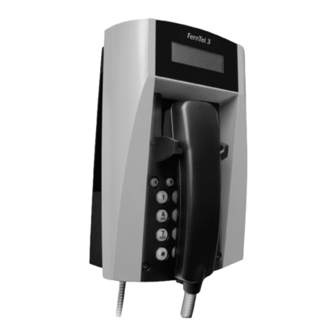
FHF FernTel 3 Z2 User manual

Explosionproof version of the
weatherproof FernTel 3 telephone
Operating manual
FHF BA 9620-64 04/10
FernTe l 3 Z2

2
The FernTel 3 Z2 telephone is an explosionproof version of the weatherproof FernTel 3
telephone with all its features. The operating manual is still valid with the addition of the
following items.
Operation
The FernTel 3 Z2 telephone is used as a stationary device in areas potentially endange-
red by an explosive gas or dust atmosphere.
Designed for Device Group II and Categories 3G and 3D it may be operated within
zones 2 and 22.
The FernTel 3 Z2 telephone may only be operated in the analogue public telephone
network and via analogue terminals of branch exchanges.
Commissioning
After having been connected to the telephone line the telephone is operational.
Operating utilization position
The telephone may be mounted on a wall or used as a desk telephone.
Service
The telephone contains no serviceable parts.
Care and maintenance
The telephone is maintenance-free. Still if the operating area is highly contaminated by
dust fat oil etc. the device should be cleaned from time to time.
The device may only be cleaned using a damp cloth in order to avoid electrostatic
charging.
Never use sharp objects for cleaning.
During maintenance check accessible seals for function e.g. regarding possible
damage or positioning. If the seals are damaged operating the telephone is not allo-
wed. Damaged seals must be replaced.
Disposal
The complete device should be disposed of as electronic waste. When the device is
disassembled plastics metals and electronics components are to be disposed of
separately. In every single case the national requirements and regulations for waste
disposal must be observed.

3
Warnings and security information
This device is a explosionproof weatherproof telephone especially designed for use in
rough industrial environments.
Please note the following warnings and security information:
– The installation and adjustment of the device must be carried out by qualified per-
sonnel in accordance with the prescribed installation regulations taking the specified
types of protection into account.
– This apparatus is a Protective Class lI device and may only be connected to and
operated at the voltage it was designed for.
Make sure the connections are in perfect order.
– Make sure the telephone housing the connecting cable and the receiver cord are
not damaged. If the device is damaged it may not be operated.
– While operating the device in commercial facilities the accident prevention regula-
tions of the Employers' Liability Insurance Association regarding the use of electrical
systems and devices must be observed.
– The device may be operated solely under the stated ambient conditions. Unfavoura-
ble ambient conditions can lead to damage of the device and thus present a poten-
tial danger for the user.
Unfavourable ambient conditions include:
• Humidity of air too high (>75% rel. condensing)
• moisture dust (pay attention to the degree of protection)
• flammable gases vapours and solvents not covered by the
device’s type of protection
• too high ambient temperatures (>+55°C)
• too low ambient temperatures low (<-20°C)
– During operation of the device the temperature must not exceed nor fall below the
prescribed range of ambient temperatures. It is not allowed to operate the device
with an additional cover.
– Repairs may be carried out by the manufacturer or by a person appointed by the
manufacturer followed by a renewed product conformity inspection.
– Make sure the wiring is disconnected from the power supply upon connecting or
disconnecting the wires in the terminal room.
– If electrical connections must be carried through in the hazardous area the enclosu-
re must be opened and closed as follows:
• Remove voltage from the device
• Loosen the fastening screws from the keypad insert
• Remove the keypad insert and unfasten the keypad cable

4
• Make the connections while the device is open
• When the work is done plug the keypad back on and place the keypad insert
back on the lower part of the device.
Make sure the seal is correctly positioned and in perfect working order. Then tighten
the fastening screws in a diagonal pattern.
– Only blind plugs and cable glands as prescribed by the manufacturer may be used.
Should these points not be observed the explosion protection of the device cannot be
guaranteed. The device then poses a potential threat to the user’s life and can cause
the ignition of an explosive atmosphere.
CE symbol
The FernTel 3 Z2 fulfils the demands of the R&TTE Directive 1995/5/EC and the ATEX
directive 94/9/EC. The CE symbol confirms the conformity of the device with the
above-mentioned Directives.
EMC-Directive
The device complies with the requirements of the new EMC-directive 2004/108/EC the
low voltage directive 2006/95/EC and the R&TTE directive 1999/5/EC.
The conformity with the above directives is confirmed by the CE sign.
Technical Specifications
Electrical characteristics
Connection data DC voltage La / Lb: Ui = 66 Vdc
Ringing voltage 24 Vac - 90 Vac / 16 Hz…68 Hz
Sounder input
impedance ≥6.0 kΩat 25 Hz
≥3.5 kΩat 50 Hz
General specifications
Enquiry key (flash) for dual-tone
multifrequency only 80 ms 120 ms 600 ms
Dialling procedure Dual-tone multifrequency Frequencies according to ITU-T Q.23
Tone duration unlimited or 90 ms
Pulse dialling Pulse/Pause ratio
1.5: 1 (60 ms/40 ms) or
2:1 (66.7/33.3 ms)
Ringing volume max. approx. 95 dB(A) at 1 m distance

5
Housing Height x Width x Depth 293 x 191 x 128 mm
Weight Approx. 2300 g
Receiver Microphone Electret-foil microphone
Receiver inset dynamic receiver inset with magnetic
field generator
Connecting terminals
Labelling
Power cable 2-pin TCP/La - TCP/Lb
Secondary sounder cable 2-pin W - W1
Conductor cross section
flexible fine-wired 0.75 – 2.5 mm2/ AWG14
rigid single wired 0.75 – 2.5 mm2/ AWG14
When connecting the wire, observe the fulfilment
of the Class II requirements as follows:
1. For connection always use the required terminal (5)
2. The shielding isolation must be long enough to reach at least to the upper edge
of the cable gland.
3. The exposed conductors from which the isolation has been removed
must be situated in the terminals.
In order to avoid electrostatic discharge the potential must be evened out. ( 7)

6
Dimensions connecting cable / cable entry
Cable entries M20 x 1.5 / M12 x 1.5
Blind plugs M20 x 1.5 / M12 x 1.5
Connecting cable diameter 6 – 13 mm
Connection potential compensation 1.5 – 4 mm2
Ambient temperature range and explosion protection
Type of protection II 3 G Ex nA L IIC T5
II 3 D Ex tD A22 IP65 80°C
Ambient operating temperature -20°C ≤Ta ≤+55°C
Storage and transport temperature -25°C ≤T≤+70°C
Housing degree of protection IP 65
Labelling
Company FHF Funke+Huster Fernsig GmbH
Type FernTel 3 Z2
20°C ≤Ta ≤+55°C IP 65 Ui = 66 Vdc / 90 Vac
II 3 G Ex nA L IIC T5 /
II 3 D Ex tD A22 IP65 80°C
DEKRA BVS 07 ATEX E 098
Do not open while energized.
For cleaning moist cleaning-rag must be used
CE 0158 II 3 G Ex nA L IIC T5 /
II 3 D Ex tD A22 IP65 80°C
IECEx Ex nAnL IIC T5
IECEx BVS 08.0008

7

Subject to alterations
or errors
FHF Funke+ Huster Fernsig GmbH
Gewerbeallee 15-19 · D-45478 Mülheim an der Ruhr
Phone +49 / 208 / 82 68-0 · Fax +49 / 208 / 82 68-286
Table of contents
Other FHF Telephone manuals
