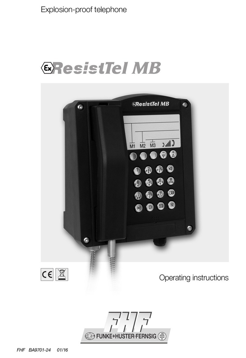
FHF ResistTel IP2/IP154 How to use

Exp osion proof and weatherproof VoIP-te ephones
Short Manua
FHF BA 9710 06/14 V8 / V9
44

BA 9710 06/14 V8/V9
ResistTel IP2 / IP152 – Short man al
ExResistTel IP2 / IP154
Brand names are sed with no g arantee that they may be freely employed. Almost
all hardware and software designations in this man al are registered trademarks or
sho ld be treated as s ch.
All rights reserved. No part of this man al may be reprod ced in any way (print,
photocopy, microfilm or by any other means) or processed, d plicated or distrib ted
sing electronic systems witho t explicit approval.
Texts and ill strations have been compiled and software created with the tmost
care, however errors cannot be completely r led o t. This doc mentation is
therefore s pplied nder excl sion of any liability or warranty of s itability for
specific p rposes. FHF reserves the right to improve or modify this doc mentation
witho t prior notice.
Note
Please read the operating man al caref lly before installing the device.
This is only a short manual. The most important operating procedures
and the mounting and installation instructions are part of this document.
For the complete configuration and operating of all features the
knowledge of the complete manual is necessary.
The complete man al is attached on the CD.
Please check the contents of the box for completeness.
Copyright © 2014
FHF F nke + H ster Fernsig GmbH
Gewerbeallee 15 – 19
45478 Mülheim an der R hr
Tel +49 (208) 8268 - 0
Fax +49 (208) 8268 - 377
http://www.fhf.de

Short Man al
ResistTel
IP2
/
IP152
Page
3
ExResistTel
IP2
/
IP154
Table of Contents
1
VoIP Telephone esistTel IP2 / IP152 and
Ex esistTel IP2 / IP154 .............................................. 5
1.1
Keypad ......................................................................... 5
1.2
Keypad Description ..................................................... 6
1.3
Display ......................................................................... 7
1.3.1
Defa lt Display .................................................................. 7
1.3.2
Men and Listing Display ................................................... 9
1.4
As-Delivered Condition ............................................... 9
1.4.1
Defa lt Version one LAN Connection with a Cable Screw Cap
...................................................................................... 10
1.4.2
Version one LAN Connection with a Female Ho sing
Connection ..................................................................... 10
1.4.3
Version one Switch LAN Mod le with two LAN Connections
with Cable Screw Cap ...................................................... 11
1.4.4
Version one Switch LAN Mod le with two LAN Connections
with Cable Screw Cap ...................................................... 11
1.5
Mounting and Installing ............................................ 11
1.5.1
LAN-Connections ............................................................. 16
1.5.1.1
Defa lt Version one LAN Connection with a Cable Screw Cap
...................................................................................... 16
1.5.1.2
Version one LAN Connection with a Female Ho sing
Connection ..................................................................... 16
1.5.1.3
Version with Switch LAN Mod le with two LAN Connections
with Cable Screw Caps .................................................... 17
1.5.1.4
Version with Switch LAN Mod le with two LAN Connections
with two Female Ho sing Connections .............................. 17
1.5.2
External Power S pply Connection ................................... 18
1.5.3
Relay Connection ............................................................ 18
1.5.4
Other Terminals .............................................................. 19
1.5.5
Sling Holder .................................................................... 20
1.5.6
General ........................................................................... 20
1.6
EMC-Directive ............................................................ 20
2
Operating Manual ...................................................... 21
2.1
Operating Basics ....................................................... 21
2.1.1
Adj sting the Vol me ...................................................... 21
2.1.2
Adj sting the Ringer Vol me ............................................ 22
2.1.3
Do not dist rb ................................................................. 23
2.1.4
Different Types of Call N mbers ....................................... 23
2.1.5
Inp t of Characters and Special Characters ....................... 23
2.2
Operating Modes ....................................................... 24
2.2.1
Changeover from Handset Mode to Handset Mode with Open
Listening ......................................................................... 25

Page
4
Short Man al
ResistTel
IP2
/
IP152
ExResistTel
IP2
/
IP154
2.2.2
Changeover from Handset Mode with Open Listening to
Handset Mode ................................................................. 25
2.2.3
Changeover from Handset Mode (with or witho t Open
Listening) to Hands Free Mode ......................................... 25
2.2.4
Changeover from Handset Mode (with or witho t Open
Listening) to Headset Mode.............................................. 25
2.2.5
Changeover from Hands Free Mode to Handset Mode ........ 25
2.2.6
Changeover from Hands Free Mode to Headset Mode ........ 25
2.2.7
Changeover from Headset Mode to Headset Mode with Open
Listening ......................................................................... 26
2.2.8
Changeover from Headset Mode with Open Listening to
Headset Mode ................................................................. 26
2.2.9
Changeover from Headset Mode (with or witho t Open
Listening) to Handset Mode ............................................. 26
2.2.10
Other Changeover of the Operating Mode ......................... 26
2.3
Call Functions ............................................................ 26
2.3.1
Answering Calls ............................................................... 26
2.3.2
Terminating a Call ........................................................... 27
2.3.3
Making Calls .................................................................... 27
2.3.3.1
Single Dialling ................................................................. 27
2.3.3.2
Block Dialling .................................................................. 28
2.3.3.2.1
Men Parameter Inp t Indirect Dialling ............................ 29
2.3.3.3
Dialling d ring existing Connections.................................. 30
2.3.4
Redialling ........................................................................ 30
2.3.5
Call Back ......................................................................... 31
2.3.6
M ting ............................................................................ 32
2.3.7
Making second Call .......................................................... 32
2.3.8
Switching ........................................................................ 33
2.3.9
Transferring a Call ........................................................... 34
2.3.10
Transferring a Call directly ............................................... 35
2.3.11
Initiating a Conference .................................................... 35
3
Technical Data weatherproof Telephones ................ 37
4
Notes ......................................................................... 39

Short Man al
ResistTel
IP2
/
IP152
Page
5
ExResistTel
IP2
/
IP154
1VoIP Telephone esistTel IP2 / IP152 and
Ex esistTel IP2 / IP154
1.1 Keypad
Figure 1: Keypad of the VoIP-Telephone

Page
6
Short Man al
ResistTel
IP2
/
IP152
ExResistTel
IP2
/
IP154
1.2 Keypad Description
Sy
m
bol
Description and Key Functions
The L
o dspeaker key is sed to control the hands free and
listening mode.
The Men key is sed to open the main men or
to
save changes.
The Disconnect key is sed to terminate calls or any men .
(short)
The Enq
iry key is sed to enable the "Hold" and "Switch"
f nctions. In idle mode, the Enq iry key is sed to call p the list
of missed calls. To exec te the enq iry f nction the Enq iry key
has to be pressed short (shorter than 0.5 seconds).
(long)
The Redial
key
is sed to select the list of 100 phone n mbers last
dialled. In the men , the redial key confirms the c rrent selection.
The telephone has no single Redial key. To exec te the redial
f nction the Redial key has to be pressed long (longer than a
second).
Arrow keys are sed for navigation in the men and browsing in
the telephone directory. The vol me can only be adj sted d ring a
call.
(long)
The
asterisk
key also serves as a m te key
. D ring a call, a long
er
press switches the microphone off or on.
...
Digit keys for entering phone n mbers
.
The
asterisk
and h
ash
keys have special f nctions. To enter asterisk
and Hash the keys
have to be pressed short (shorter than 0.5 seconds). To enter
M te (asterisk) and Shift (hash) the keys have to be pressed long
(longer than a second). After pressing of shift the digit keys (1 – 9
and 0) become f nction keys (F1 – F10). After exec ting a
f nction key the shift mode is ended.
The Clearing key is sed in inp
t mode to delete the characters
left to the c rsor.

Short Man al
ResistTel
IP2
/
IP152
Page
7
ExResistTel
IP2
/
IP154
Sy
m
bol
Description and Key Functions
(long)
The headset key
is sed to make and to end a call in the headset
mode. The phone ResistTel IP2 / IP152 has no single headset key.
To exec te the headset key f nction the key has to be pressed
long (longer than a second) and then the lo dspeaker key has
to be pressed. The headset key can be sed only, if the headset is
config red to on (see man al). This makes sense only, if a
headset is connected to the phone.
Table 1: Keys and Function Elements
1.3 Display
The displays of the VoIP Telephones ResistTel IP2 / IP152 and
ExResistTel IP2 / IP154 have 7 lines with max. 30 characters and a state line for
showing information.
1.3.1 Default Display
The name and telephone n mber of the c rrent registration is displayed in the first
line.
The middle lines display special information relating to the condition.
The date, time and registration stat s is displayed in the last line.
1 4 2 3 5
Torsten 72
06.04.10 14:40
Figure 2: Default Display (Idle State)
In the b sy state state-information, date, time and the d ration of the active
connection are displayed in the last line.

Page
8
Short Man al
ResistTel
IP2
/
IP152
ExResistTel
IP2
/
IP154
1 4 2 5 3
Thorsten 72
06.04.10 14:40 0:12
Figure 3: Default Display (Busy State)
Posit
i
on
Sy
m
bol
Descripti
on
1
Name (H.323
or SIP
ID or nickname of the PBX config ration)
2
Stat s line; provides information on the c rrent stat s of the
telephone by means of the following symbols.
06.04.10
Date
14:00
Time
No connection to t
he gatekeeper
Connection established to the gatekeeper
Connection established to the secondary gatekeeper
Connection to the gatekeeper broken. (Both symbols are
displayed in m t al change
Open
listening
Hands free
Mode
Microphone
switched off (symbol flashing)
Call diversion activated
Handset activate
Headset active
Telephone locked
Calling n mber transmission locked
3
Own call n mber (E.164)
4
Called party
Calling party
Unknown number/name, unresolved number
Diverting party
Transferring party
Returning call
Call pending
Call on hold
5
Shift Mode
Headset configured
A dio connection of the active call is scrambled (SRTP)
0:12
D ration of the active call
Table 2: Contents of the Default Display

Short Man al
ResistTel
IP2
/
IP152
Page
9
ExResistTel
IP2
/
IP154
1.3.2 Menu and Listing Display
The first six lines are sed for the men and listing display.
The last line is sed for display of men level, display name, scroll information and
type of entry.
1 2 3
display name
Figure 4: Menu and Listing Display of the VoIP Telephone
Posit
i
on
Sy
m
bol
Description
1
Men or listing level 0
<
Men or listing level 1
Men or list
ing level 2
Men or listing level 3
Men or listing level 4 or lower
2
Display name
3
Scrolling p possible
Scrolling p
and down
possible
Scrolling down possible
a
A
lphan meri
cal
inp t
1
N merical inp t
Choice
,
next level
Table 3: Contents of the Menu and Listing Display
1.4 As-Delivered Condition
The phone is available for delivery in different versions.
•Handset with armed co rt.
•Single LAN connection or switch LAN mod le with two LAN connections with
internal connection and cable screw connection or external LAN connection
and pl g in connection.
•Ho sing in black or colo red in red or bl e.
•Some Sealing pl gs to connect option eq ipment
•Optional: max. 5 cable screw caps
•Optional: relay mod le

Page
10
Short Man al
ResistTel
IP2
/
IP152
ExResistTel
IP2
/
IP154
Accessories (optional):
- Headset with connection cable and attachment of the bracket.
- LAN connector from Phoenix Contact Type VS-08-RJ45-5-Q/IP67, order-no.:
1656990
- LAN female connector for cable mo nting from AMP NETCONNECT (TE
Connectivity), order-no. 116604-2
- Cable screw cap
- Sealing pl gs
- 2 keys for TORX socket screws TX20, TX30
1.4.1 Default Version one LAN Connection with a Cable Screw
Cap
•1 LAN connection internal
•Ho sing with 1 cable screw caps and 2 bored holes with sealing pl gs at the
pper side.
Box contents
The scope of the delivery incl des:
- Telephone
- Printed short man al
- Man al on CD
- 1 LAN female connector for cable mo nting from AMP NETCONNECT (TE
Connectivity), order-no. 116604-2
- 2 keys for TORX socket screws TX20, TX30
1.4.2 Version one LAN Connection with a Female Housing
Connection
•1 LAN connection female ho sing connection
•1 LAN connection (witho t LAN interface) and sealing pl g at the ho sing
•Ho sing with 1 bored hole with sealing pl g at the pper side
Box contents
The scope of the delivery incl des:
- Telephone
- Printed short man al
- Man al on CD
- LAN connector from Phoenix Contact Type VS-08-RJ45-5-Q/IP67, order-no.:
1656990
- 2 keys for TORX socket screws TX20, TX30

Short Man al
ResistTel
IP2
/
IP152
Page
11
ExResistTel
IP2
/
IP154
1.4.3 Version one Switch LAN Module with two LAN
Connections with Cable Screw Cap
•2 LAN connections internal
•Ho sing with 1 cable screw caps and 2 bored holes with sealing pl gs at the
pper side.
Box contents
The scope of the delivery incl des:
- Telephone
- Printed short man al
- Man al on CD
- 1 LAN female connector for cable mo nting from AMP NETCONNECT (TE
Connectivity), order-no. 116604-2
- 2 keys for TORX socket screws TX20, TX30
1.4.4 Version one Switch LAN Module with two LAN
Connections with Cable Screw Cap
•1 LAN connection female ho sing connection
•1 LAN connection and sealing pl g at the ho sing
•Ho sing with 1 bored hole with sealing pl g at the pper side
Box contents
The scope of the delivery incl des:
- Telephone
- Printed short man al
- Man al on CD
- LAN connector from Phoenix Contact Type VS-08-RJ45-5-Q/IP67, order-no.:
1656990
- 2 keys for TORX socket screws TX20, TX30
1.5 Mounting and Installing
The device m st be installed on a plane s rface only, in vertical operating position.
Loosen the cover screws (2) (see Fig re 6 to Fig re 8) and detach the pper part of
the telephone (1). If the optional accessory headset or a second earpiece is being
employed, attach the bracket (10) sing two screws (11) to the rear panel of the
lower part of the telephone. (With the accessories named before, the bracket and
screws are in the scope of delivery. With all accessories a cable gland is delivered.)
P t fo r screws, having a head diameter of 10 to 13 mm into the holes (20) and
attach the lower part of the telephone (3) to the wall or to a holder.

Page
12
Short Man al
ResistTel
IP2
/
IP152
ExResistTel
IP2
/
IP154
G ide the telephone wire thro gh the cable screw cap (4) and place it on the
terminals. Only wires having a sheath diameter of 5 to 9 mm sho ld be sed beca se
otherwise the IP66 ho sing protection standard is not g aranteed.
Prior to assembly, check cover seal for tightness. Using the pl g connector (7), pl g
the ribbon cable onto the pin contact strip (8) in the pper part of the ho sing.
Attach the pper part of the telephone and fasten it to the lower part of the
telephone with the fo r cover screws (2). Upon disassembly of optional accessories,
s ited sealing pl gs m st be sed to close the res lting openings.
In this telephone connected cords may have hazardo s voltages.
To ens re that no water gets into the enclos re it is essential that no gaskets are
damaged d ring installation. The ingress of water can ca se accessible parts of the
telephone to become live.
Installation and connection m st be carried o t by competent personnel familiar with
electrical and network installations.
Figure 5: Drilling Diagram Wall Mounting

Short Man al
ResistTel
IP2
/
IP152
Page
13
ExResistTel
IP2
/
IP154
The diameter of the drilled hole is dependent on the screw employed (screw
diameter max. 8 mm) and the type of s pporting base material (steel, wood,
concrete, plasterboard etc.) and m st be chosen accordingly. The distance in the
width is 201 mm and the distance in the height is 195 mm.
Figure 6: Set View
Figure 7: Inside View of Telephone upper Part

Page
14
Short Man al
ResistTel
IP2
/
IP152
ExResistTel
IP2
/
IP154
Figure 8: Inside View of Telephone lower Part
Figure 9: Connection Diagram with Single LAN Module
1 2 3 4 5 6 7 8 9 10
11
12
13
X
1
0
X11
X1
X2
X3
X4
X5 X6
LAN
PoE
X7
X
8
X
1
2
X
9

Short Man al
ResistTel
IP2
/
IP152
Page
15
ExResistTel
IP2
/
IP154
Figure 10: Connection Diagram with Switch LAN Module
Connector
description
X1
empty
X2
Lo dspeaker
(
left
)
X3
Heater of the Display
X4
Ill mination of the Display
X5
Display
X6
LAN Mod le
X7
Keypad
X8
Hookswitch
(Reed Contact)
X9
RS232 Mod le (optional)
X10
Amplifier Mod le (optional)
X
11
Handset
X12
Relay Mod le (optional)
LAN PoE
LAN with PoE (LAN
-
Link, single LAN Mod le)
LAN1 PoE
LAN1 with PoE (LAN
-
Link, Switch LAN Mod le)
LAN2 (PC)
LAN2 (PC
-
Link, Switch LAN Mod le)
1
-
13
Terminals (Config ration see the following Chapters)
Table 4: Plug in Connectors and Terminals of the esistTel IP2 / IP152
with Hardware-ID: 103
1 2 3 4 5 6 7 8 9 10
11
12
13
X
1
0
X11
X1
X2
X3
X4
X5
X7
X
8
X
1
2
X
9
X6
LAN1
PoE LAN2

Page
16
Short Man al
ResistTel
IP2
/
IP152
ExResistTel
IP2
/
IP154
1.5.1 LAN-Connections
1.5.1.1 Default Version one LAN Connection with a Cable
Screw Cap
The telephone has in the defa lt version one internal LAN-connection with a cable
screw cap. For the connection a LAN cable m st be p lled thro gh the cable screw
cap. Inside the phone the female LAN connection from AMP NETCONNECT (TE
Connectivity) has to be pressed on the cable (Refer to chapter 1.4 beginning on page
9). A female LAN cable connector belongs to the as-delivered condition. With the
inside the phone existing little LAN connection cable, the LAN can be connected with
the phone.
The LAN delivery can be available with PoE (Power over Ethernet). Alternatively the
phone can be s pplied with power external.
All not sed cable feed thro gh have to be closed with sealing pl gs.
1.5.1.2 Version one LAN Connection with a Female Housing
Connection
The phone has in this version one LAN-connection with a female LAN connection at
the ho sing. LAN-cable, sed for pl g into the telephone ResistTel IP2 / IP152, have
to be adapted with a connector from Phoenix contact (Refer to chapter 1.4 beginning
on page 9), to preserve the IP66 degree of protection. A LAN cable connector
belongs to the as-delivered condition.
The LAN-lead wire has to be connected to the connector in the front. Die LAN lead
wire can to be with PoE (Power over Ethernet). Alternatively the phone can be
s pplied with power external.
The second LAN connector of the ResistTel IP2 / IP152 is a blind connector closed
with a protective cap to preserve the IP66 degree of protection
All not sed cable feed thro gh have to be closed with sealing pl gs.
Caution
Yo can se PoE (Power over Ethernet) or an external connection to s pply the
ResistTel IP2 / IP152 with power.
Don’t se both at the same time, to prevent damage to the eq ipment.

Short Man al
ResistTel
IP2
/
IP152
Page
17
ExResistTel
IP2
/
IP154
1.5.1.3 Version with Switch LAN Module with two LAN
Connections with Cable Screw Caps
The telephone has in this version two internal LAN-connections with a cable screw
cap. For the connection the LAN cable m st be p lled thro gh the cable screw cap.
Inside the phone the female LAN connection from AMP NETCONNECT (TE
Connectivity) has to be pressed on the cable (Refer to chapter 1.4 beginning on page
9). A female LAN cable connector belongs to the as-delivered condition. With the
inside the phone existing little LAN connection cable, the LAN can be connected with
the phone.
The LAN1 delivery can be available with PoE (Power over Ethernet). Alternatively the
phone can be s pplied with power external.
The LAN2 delivery doesn’t s pport PoE. Also it can’t be sed to connect a phone
directly, which sho ld be powered with PoE.
All not sed cable feed thro gh have to be closed with sealing pl gs.
1.5.1.4 Version with Switch LAN Module with two LAN
Connections with two Female Housing Connections
The phone has in this version two LAN-connections with a female LAN connection at
the ho sing. LAN-cable, sed for pl g into the telephone ResistTel IP2 / IP152, have
to be adapted with a connector from Phoenix Contact (Refer to chapter 1.4
beginning on page 9), to preserve the IP66 degree of protection. A LAN cable
connector belongs to the as-delivered condition.
The LAN-lead wire has to be connected to the connector in the front. Die LAN1 lead
wire can to be with PoE (Power over Ethernet). Alternatively the phone can be
s pplied with power external.
The second LAN connector of the ResistTel IP2 / IP152 doesn’t s pport PoE. Also it
can’t be sed to connect a phone directly, which sho ld be powered with PoE.
If the second LAN connector of the ResistTel IP2 / IP152 will not be sed, it has to
be closed with the at the phone available protection pl g to preserve the degree of
protection IP66.
All not sed cable feed thro gh have to be closed with sealing pl gs.

Page
18
Short Man al
ResistTel
IP2
/
IP152
ExResistTel
IP2
/
IP154
1.5.2 External Power Supply Connection
An external power s pply can be adapted to the terminals 5 (+) and 6 (-). The
voltage has to be:
Witho t sing the optional voltaic separated inp ts: 15 V – 57 V DC, 12.95 W
With sing the optional voltaic separated inp ts: 21,5 V – 57 V DC, 12.95 W
If the external power connection will be sed, yo m st not se PoE at the LAN
connection.
1.5.3 elay Connection
The phone can be b ild p with a relay mod le with two relays with a single
changeover switch optional.
The maximal breaking capacity of a relay is depending on the voltage:
•240 V, 6 A, AC
•24 V, 6 A, DC
•32 V, 5 A, DC
•48 V, 1 A, DC
Figure 11: Connection Diagram elay Module
Caution
Do not open the ho sing of the telephone while the relay contacts are energized.
K1
Relay 1 Relay 2
1 2
3
1
2
3

Short Man al
ResistTel
IP2
/
IP152
Page
19
ExResistTel
IP2
/
IP154
Connector
Description
K1
Cable to the mai
n board (connection to pl g in X12)
1 (relay 1)
Idle
contact relay 1
2 (relay 1)
Base
contact relay 1
3 (relay 1)
Switching contact relay 1
1 (relay 2)
Idle
contact relay 2
2 (relay 2)
Base
contact relay 2
3 (relay 2)
Switching contact relay 2
Table 5: Plug in Connectors and Terminals of the elay Module of the
Telephone esistTel IP2 / IP152
Pay partic lar attention to the following points if hazardo s voltages (>48V) are to
be connected to the relay o tp ts:
•Cable and cords m st be ins lated and have to be cond cted below the cover.
•The circ its that the relay o tp ts are connected to m st be of the same type;
i.e. both mains, both SELV or both TNV circ its.
•It is not permissible to connect different types of circ its to these relays.
1.5.4 Other Terminals
The terminals 1 – 4 are for connecting a headset. A detailed description is enclosed
in the man al.
The terminals 7 – 13 five voltaic separated inp ts are provided. All of the voltaic
separated inp ts have a common n ll potential. Closing contacts (e. g. external
p sh-b ttons) can be connected at the inp ts. The maxim m switching load for the
closing contacts is 60 V DC, 10 mA.
Terminal
Description
7
N ll potential of the voltaic
separated inp ts
8
N ll potential of the voltaic
s
eparated inp ts
9
Inp t 1
10
Inp t 2
11
Inp t 3
12
Inp t 4
13
Inp t 5
Table 6: Terminals of the voltaic separated Inputs

Page
20
Short Man al
ResistTel
IP2
/
IP152
ExResistTel
IP2
/
IP154
Caution
While sing the voltaic separated inp ts with external power s pply, the inp t
voltage has to be 21.5 V – 57 V DC.
1.5.5 Sling Holder
The holding strength for the handset is contin o sly adj stable.
Loosen the screws (12) and move the stopping catches (13) (See Fig re 6 on page
13). P shing the stopping catches together increases the holding strength whereas
p lling them apart red ces it. Tighten the screws again.
1.5.6 General
The receiver is eq ipped with a leakage field spool for co pling of hearing aids. Users
of a hearing aid with ind ctive receiver may receive the signal from the receiver inset
directly.
1.6 EMC-Directive
The device complies with the req irements of the new EMC-directive 2004/108/EC,
the low voltage directive 2006/95/EC and the R&TTE directive 1999/5/EC.
The conformity with the above directives is confirmed by the CE sign.
This manual suits for next models
1
Table of contents
Other FHF Telephone manuals
