FHF InduTel IP User manual

IP
Weatherproof telephone
FHF BA 9605-05 09/16 V1
Operating instructions

BA9605-0EN 09/16 V15-
Manual
InduTel IP
Brand names are used with no guarantee that they may be freely employed. Almost
all hardware and software designations in this manual are registered trademarks or
should be treated as such.
All rights reserved. No part of this manual may be reproduced in any way (print, pho-
tocopy, microfilm or by any other means) or processed, duplicated or distributed us-
ing electronic systems without explicit approval.
Texts and illustrations have been compiled and software created with the utmost
care, however errors cannot be completely ruled out. This documentation is there-
fore supplied under exclusion of any liability or warranty of suitability for specific
purposes. FHF reserves the right to improve or modify this documentation without
prior notice.
Note
Please read the operating manual carefully before installing the de-
vice.
Please check the contents of the box for completeness.
Copyright © 2016
FHF Funke + Huster Fernsig GmbH
Gewerbeallee 15 –19
45478 Mülheim an der Ruhr
Tel +49 (208) 8268 - 0
Fax +49 (208) 8268 - 377
http://www.fhf.de

3
Table of Contents
1About this Manual ....................................................... 5
1.1 Tips for Reading .......................................................... 5
1.2 Overview of the Chapters ........................................... 6
2General Notes on Operation........................................ 8
2.1 At the Time of Delivery ............................................... 8
Contents of the Packaging ................................................. 82.1.1
Default Settings of the Telephone ...................................... 92.1.2
2.2 Assembly and Installation .......................................... 9
Wall Assembly................................................................... 92.2.1
Connection of a separate DC Voltage Supply ..................... 102.2.2
Connection of the internal Relay Contact .......................... 102.2.3
Terminal Configuration .................................................... 102.2.4
Assembly of LAN-Connector RJ45 ..................................... 112.2.5
Crimping Tool ................................................................. 112.2.5.1
RJ45 Plug-in Connector with Insulation Displacement2.2.5.2
Termination .................................................................... 12
2.3 Operating Elements................................................... 12
Version with Keypad........................................................ 122.3.1
2.4 Dimensions................................................................ 13
2.5 Operation .................................................................. 14
Calling / Taking Call......................................................... 142.5.1
Dialling ........................................................................... 142.5.2
Speed Dialling ................................................................. 142.5.3
Re-Dialling ...................................................................... 142.5.4
Disconnecting ................................................................. 142.5.5
Announcement of the Current IP Address ......................... 142.5.6
3Web Server................................................................ 15
3.1 Authorization............................................................. 15
3.2 Menus ........................................................................ 16
Info................................................................................ 163.2.1
Info................................................................................ 163.2.1.1
About ............................................................................. 173.2.1.2
System Details ................................................................ 173.2.1.3
Configuration .................................................................. 193.2.2
Network Settings............................................................. 193.2.2.1
SIP Settings .................................................................... 203.2.2.2
Phone Settings................................................................ 243.2.2.3
Audio Settings................................................................. 253.2.2.4
Speed Dial ...................................................................... 263.2.2.5
System Administration ..................................................... 273.2.3
Username & Password..................................................... 273.2.3.1
Manual Upgrade.............................................................. 283.2.3.2
Reset Settings................................................................. 29
3.2.3.3

4
4General Notes............................................................ 31
4.1 Service....................................................................... 31
4.2 Servicing and Maintenance ....................................... 31
4.3 Warnings and Safety Instructions ............................ 31
5Abbreviations ............................................................ 33
6Overview ................................................................... 42
6.1 Tables ........................................................................ 42
6.2 Figures....................................................................... 42
7Index ......................................................................... 43
8Technical Data........................................................... 44
9Declaration of EC-Conformity ................................... 46
9.1 Support...................................................................... 46
9.2 Disposal ..................................................................... 46

5
1About this Manual
This manual describes the operation and administration of the weatherproof VoIP
telephone InduTel IP. In order to create a VoIP gateway or a VoIP PBX, please con-
tact the gateway or PBX manufacturer for more information. All advice and instruc-
tions for the operation of the VoIP telephone must be followed carefully and the tel-
ephone should only be used as specified.
This manual is updated regularly.
1.1 Tips for Reading
Symbols can be found together with a box at various chapters of this manual. They
are intended to refer you to chapters of particular significance, as shown below.
Note
Notes provide you with information that you may first need to be-
come familiar with in order to configure the equipment properly.
Tip
Tips provide you with information on how to operate the terminals in
a particularly easy or convenient way.
Caution
Notes provide you with information that you may first need to be-
come familiar with in order to configure the equipment properly.

6
1.2 Overview of the Chapters
This manual offers extensive information about the VoIP telephone InduTel IP. Apart
from the general basics, it also offers detailed operating instructions as well as ad-
ministrator instructions.
General information on the phone is provided in chapter 2. It contains the setup of
the phone and descriptions of the available keys.
Chapter 2.5 is particularly interesting for the user of the phone. Here it is shown in
detail, which possibilities are available.
Chapter 3 is intended for the administrator of the system. The Web interface allows
for comfortable administrative setup of the VoIP telephones.
Note
This configuration can be accessed after password entry only. Refer
to chapter 2.
Follow the safety instructions in the manual at all times!
Note
Parameters that are transmitted to the telephone per DHCP cannot be
overwritten by a local configuration.

7
Tip
For searching of special information in this document you can use the
following assistance:
Table of contents
Index
Abbreviations
Overview tables
Overview figures
This document is available as a PDF file. With a PC it is possi-
ble to search selective for keywords.
This document is available in the following languages:
oGerman
oEnglish
For general questions concerning the operation of VoIP telephones or
information that must be respected for operation with special PBX’s or
gatekeepers, a FAQ (frequently asked questions) document is availa-
ble.

8
2General Notes on Operation
1. The InduTel IP is a VoIP (Voice over Internet Protocol) telephone and is oper-
ated on a 10/100 BaseT Ethernet network. The connections are established
via the Session Initiation Protocol (SIP).
2. The power supply may be established via Power over Ethernet (PoE) from the
network or via a separate direct current voltage source (see chapter 2.2.2).
3. The programming and parameter setting are carried out solely via the web
server of the telephone. The web server can be reached via the standard web
browser of a PC. In order to access the web server, entering the username
and the password is mandatory. The factory settings for the username and
password are:
Username: admin
Password: fhf
On default since software version 1.0 r8xx the device is working in the DHCP
client mode. If no DHCP server is available, then the device uses the preset IP
address 192.168.0.77 and mask 255.255.255.0.
4. The telephone has a handset rest with a magnetic contact as a hook switch.
In order to end an existing call, the handset must be hung up, or the cut-off
key (see chapter 2.3.1) on the keypad must be pressed.
5. The internal relay contacts only allow voltages of 30 VAC or 60 VDC to be
switched. The maximum permissible current depends on the mode of opera-
tion (see chapter 8).
6. The handset of the telephone is fitted with a stray field coil for connection to
hearing aids. Those who wear a hearing aid with an inductive receiver can re-
ceive the signal of the earphone capsule directly over the hearing aid.
2.1 At the Time of Delivery
Contents of the Packaging2.1.1
Telephone InduTel IP
These operating instructions
LAN device connector plug

9
Default Settings of the Telephone2.1.2
DHCP mode
client
IP address (fall back)
Mask (fall back)
192.168.0.77
255.255.255.0
Announcement of the current
dial *558800
Master Reset to Factory
dial **314159265359
Username
admin
Password
fhf
Number redial memory
empty
Speed dial memory
empty
Relay function
switched off
Tone call melody
2
Tone call volume
3
Handset volume
5
Microphone sensitivity
6
Table 1: Default Settings of the Telephone
2.2 Assembly and Installation
Since all telephones have the same preset IP address, the network settings should be
configured with the web server of the telephone before the telephone is assembled.
The username and password at the time of delivery should be changed for security
reasons.
The assembly of the telephone should only be carried out by qualified specialist per-
sonnel.
Wall Assembly2.2.1
Assembly is carried out on a firm and even surface.
Fasten the telephone to the wall with four screws (of a size of up to Ø 8 mm).
Lead the LAN cable trough the cable screws and fasten the delivered device connect-
or plug in to the LAN cable and plug the connector into the RJ45 plug-in. Then fasten
the cable screw.
10
Connection of a separate DC Voltage Supply2.2.2
If a PoE supply is not available, the telephone can also be operated with a DC volt-
age of 24 V to 48 V.
Take off the handset. Unscrew the keypad plate. Guide the supply line through the
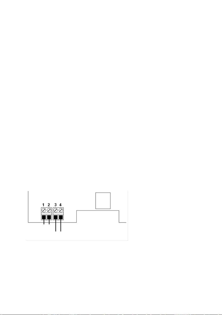
screwed cable gland and put the two connecting leads onto the terminals 3 and 4
(any polarity). Fix the supply line with the cable gland. Make sure that the cable con-
nection to the keypad is plugged in. Then place the keypad plate back onto the tele-
phone and fasten it with four screws. Then put the handset back.
Connection of the internal Relay Contact2.2.3
Take off the handset. Unscrew the keypad plate. Guide the connection line through
the screwed cable gland and put the two connecting leads onto the terminals 1 and
2. Fix the connection line with the screwed cable gland. Make sure that the cable
connection to the keypad is plugged in. Then place the keypad plate back onto the
telephone and fasten it with four screws. Then put the handset back.
Only use lines with a sheathing diameter of 5 mm to 9 mm, since the degree of pro-
tection IP 66 is not ensured otherwise. If you wish to use a separate DC voltage
supply and the relay contact at the same time, you must use a four-core cable.
If a separate DC voltage supply and connection of the internal relay contact are not
required, it is to be ensured that the sealing element is in the screwed cable gland.
Terminal Configuration2.2.4
Figure 1: Terminal Configuration
Relay contact
DC voltage supply

11
Assembly of LAN-Connector RJ452.2.5
Figure 2: LAN Connector RJ45
Figure 3: PIN Description according to T568A and T568B
PIN assignment depends on the condition of installation on site.
Crimping Tool2.2.5.1
recommended tool:
LogiLink crimping tool Universal
WZ0003
Figure 4: LogiLink Crimping Tool Universal WZ0003

12
RJ45 Plug-in Connector with Insulation Displacement2.2.5.2
Termination
If Ethernet cables with rigid conductors are used, then it is recommended to use
RJ45 plug-in connectors with insulation displacement termination. Because these
plug-in connectors can be mounted without tools, the can be used with strand wires
without using a crimping tool for mounting. A usable plug-in connector is the indus-
trial Ethernet plug-in connector of the company Weidmüller, order number: IE-PS-
RJ45-FH-BK.
2.3 Operating Elements
Version with Keypad2.3.1
________________________
Digit keys
Speed dialing (1st key)
Disconnect
Re-dialing
Figure 5: Operating Elements
13
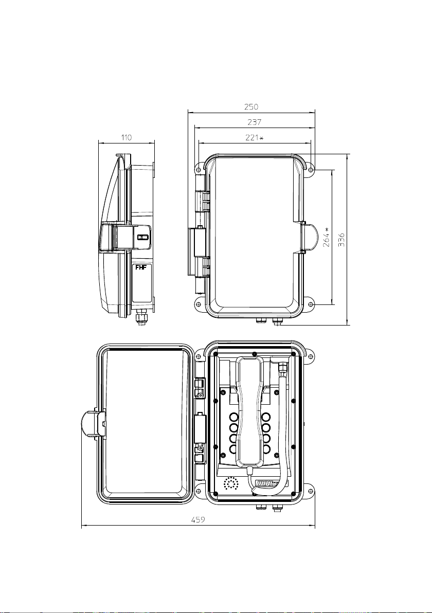
2.4 Dimensions
Figure 6: Dimensions in mm

14
2.5 Operation
Calling / Taking Call2.5.1
You can answer a call by taking off the handset or dial the number of the person you
wish to speak to.
Dialling2.5.2
You can enter the desired telephone number using the number keys. Once a connec-
tion has been established, you can transmit tone dialling signals with the number
keys, star and hash key.
Numbers are dialled in so-called block dialling. This means that the numbers must be
entered quickly one after the other. After a pause of a certain length, the numbers
entered so far are then dialled.
Speed Dialling2.5.3
With the key and then a number key you can dial telephone numbers you saved
previously using the web server of the InduTel IP.
Re-Dialling2.5.4
After taking off the handset and pressing the redial key, the telephone number last
entered will be automatically dialled as long as the InduTel IP has not been restart-
ed.
Disconnecting2.5.5
If you want to end a conversation and start a new one straight away, you do not
need to hang up the handset but merely press the cut-off key. The old conversation
will be terminated and after a short time you will hear the dial tone. You can now
enter the telephone number for the new conversation.
Announcement of the Current IP Address2.5.6
The InduTel IP is able to announce the current IP address. For this purpose, the fol-
lowing “telephone number” must be dialled:
IP announcement = *558800
The address will be announced on the telephone earpiece.
15
3Web Server
This section describes the administration/configuration of the telephone InduTel IP.
All functions and properties of the telephone can be set via the web server.
Note
Before parameters become effective they have to be saved with "Ap-
ply Changes".
In the certain parameters, the InduTel IP must be restarted in order
for them to take effect.
3.1 Authorization
The web server is accessed via a web browser. You should use an up-to-date version
of a commonly used web browser.
In the delivery condition the DHCP client mode is active. If no DHCP server is reach-
able, then the telephone falls back to the following network settings:
IP-Address: 192.168.0.77
Net mask: 255.255.255.0
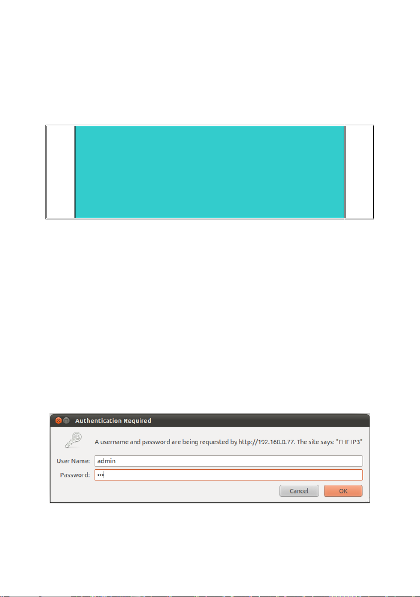
You will be requested to enter username and password.
The factory settings for the username and password are:
User Name: admin
Password: fhf
Figure 7: Authorization

16
3.2 Menus
The web server is the central control unit and is divided into various main menus and
submenus, which are arranged on the left-hand side.
Info3.2.1
In the main menu info different information submenus are merged.
Info3.2.1.1
If you are successfully authorized, you will be taken to the main menu "Info" and the
submenu of the same name.
This browser page is divided into four sections:
Device Info: Device and network parameters as well as parameters for the
fall back setups are displayed here. Furthermore information about host
names, NetBIOS configuration and NTP server are displayed.
SIP Configuration: SIP account settings are displayed here
Status: This part indicates which state the telephone is in (unregistered,
ready, dialling, startcall, talking, busy, incoming, callended, fault) and what
the registration status of the PBX is (auth., Request, Registered, Unregistered,
- ).
Version: The current hardware and software versions are shown here.
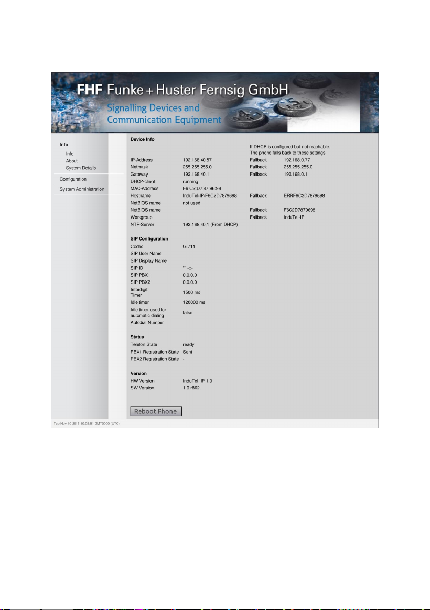
17
Figure 8: Info
About3.2.1.2
The GNU licence terms are given in the submenu "About".
System Details3.2.1.3
In the submenu "System Details" there is additional information for the adminis-
trator. Moreover, the functions "PING" and "TRACE ROUTE" are available with
which another IP address can be pinged or traced from the telephone.

18
.
Note
The "TRACE" command in particular can take up a great amount of
time. Even if the web server indicates a "Timeout / Refresh Error"
of the page, the "TRACE ROUTE" or "PING" command is still active
in the background and the result can be shown later on by means of
"Show Last Ping" or "Show Last Trace" –as long as no reboot or
something similar interrupts the execution of the command. There-
fore it is recommended to limit the number of pings or hops and to
start with a small number (one or two) and to increase these step by
step if necessary.
Figure 9: System Details

19
Configuration3.2.2
In order to save the entered data on the following menus, the "Apply Changes"
button must be clicked.
For the changes to take effect, the telephone must be restarted ("reboot").
Network Settings3.2.2.1
In this submenu you can choose whether the IP address is to be assigned dynamical-
ly via the network (DHCP) or manually. In case of manual assignment, the fields
"Subnet Mask" and "Gateway Address" must additionally be entered in respect
to the network parameters. You can also configure the IP address of an NTP server
so that the date and time (GMT) in the bottom left-hand corner of the web server
are shown correctly.
In the field "IP Address" will be always shown the actual IP address. Therefore a
dynamically received IP address can be used static. If the DHCP server transfers a
NTP address, this information will be used nether the less to the information in the
field "NTP Server". If the DHCP server distributes more than one NTP address, then
the first one will be used.
For the identification of the telephone in a network a host name can be defined. The
length is limited to 255 characters and may consist of the characters [a-z][A-Z][0-
9][-] and [.] (RFC952). With the field "Append MAC-Address" the MAC address of
the telephone can be appended to the host name for a unique identification. If the
field is activated and the host name is not set, then the MAC address only (without
leading hyphen) will be used as host name.
For supporting compatibility with windows networks a NetBIOS name and a
workgroup can be defined and activated with the field "Use NetBIOS name".
With the parameters below "Fallback Settings" can be defined the network set-
tings to be used, if the phone is set to DHCP client mode and no DVCP server is
reachable. This configuration will be displayed at the "Info" page. The host name in
this case is not changeable and consists always of the string "ERR" followed by the
MAC address of the telephone.

20
Figure 10: Network Settings
SIP Settings3.2.2.2
You will find all settings related to SIP here. There are 4 sections altogether.
SIP Account Settings
In this section "User ID", "Displayname", "Phone Number" and "Do-
main" can be set. If "Displayname" as well as "Phone Number" are set,
the "Displayname" will be used for registration on the PBX.
Table of contents
Other FHF Telephone manuals


