FHF RESISTEL MB User manual

Explosion-proof telephone
Operating instructions
FHF BA9701-24 01/16

2
Foreword
Our explosion-proof, weatherpoof phone offers precision, comfort,
extended service life and reliability. It is programmable and it can
withstand harsh environmental conditions. The phone can be used
under severe conditions including seawater, high humidity, dust and it
withstands strong mechanical shock in connection with explosion
protection. It is fitted with an indestructible keypad made of V4A steel
and an extremely robust body made of shock and impact-resistant
compression moulded plastic. All components used for making this
phone are resistant against lye and lubricants. The 21-part keypad
optimised for "use with gloves" and made of V4A steel is easy to
operate and thus meets all requirements for a modern and reliable
communications device. The ExResistTel MB phone offers a reliable
communication channel when connected to the public network or to
PBX systems.

3
Table of contents
General operating conditions ............................................................. 5
Device overview ................................................................................. 6
Keypad ............................................................................................... 9
Package contents ............................................................................... 9
Explosion protection - device description........................................... 10
Characteristic data ............................................................................. 13
Identification ....................................................................................... 14
Assembly and installation .................................................................. 15
Connection diagram ........................................................................... 16
Support hook...................................................................................... 16
Hole pattern ....................................................................................... 17
Putting into service ............................................................................ 17
Maintenance....................................................................................... 17
Handset operation ............................................................................. 18
Open listening ................................................................................... 18
Hands-free mode ............................................................................... 18
Using the headset ............................................................................. 19
Operation ......................................................................................... 20
Receiving calls ............................................................................ 20
Making a call ................................................................................ 20
Redialling .................................................................................... 20
Making a second call ................................................................... 20
Operation with active phone lock .................................................. 20
Changing the phone settings ...................................................... 21
Signal tones ................................................................................ 21
Configuration .................................................................................... 22
Setting the ringer volume ............................................................ 22
Selecting a ringtone .................................................................... 22
Setting the handset volume ........................................................ 22
Setting the speaker volume for open listening .............................. 22
Setting the speaker volume for hands-free operation .................. 22
Setting the headset volume ........................................................ 22
Setting or deleting phone numbers for speed dialling.................. 23
Setting the call procedure ........................................................... 23
Storing or deleting a trunk access code ...................................... 23
Setting the length of pause after dialling a trunk access code
......... 23
Setting the duration of the loop current interruption (flash time)
when pushing the second call button
........................................... 24
Activating/deactivating the change lock ...................................... 24
Determine phone lock .................................................................. 24
Determine or delete a preset direct call number .......................... 24
Setting the PIN number................................................................ 25
Restoring factory settings ............................................................ 25
Setting the procedure when disconnecting the headset .............. 25
Factory settings ................................................................................. 26

4
Technical data .................................................................................. 27
Service ............................................................................................. 30
Care and maintenance ...................................................................... 30
Disposal ........................................................................................... 30
Warning and safety instructions ....................................................... 30
CE symbol ......................................................................................... 31

5
General operating conditions
1. The ExResistTel MB weatherproof phone can be connected to the
telephone lines of analogue exchanges.
2. The handset is fitted with a stray field coil for connecting hearing aid
devices. Persons wearing a hearing aid device with an inductive
receiver can directly receive the signal of the earphone.
3. The phone has a receiver mount with a reed contact hook switch.
The handset must be placed back on the mount to end the call. A
conversation is ended and a new call is started by pressing the
disconnect button on the keypad (see page 9).
4. If the you do not make a selection within 2 minutes, the exchange
can cut off the power supply. Then you will stop hearing the dial
tone. In this case, please place back the handset, wait for 2 seconds
and lift the handset again.
5. An acknowledgement tone confirms that the settings have been
stored.
6. When you receive a call, the ExResistTel MB phone rings with the
selected volume.
7. Changing the settings can be prevented by setting a PIN number.
Forgetting the PIN number is similar to losing a key. If you forgot the
PIN number, please contact our technical support service.
8. There is a warranty period of 36 months from the date of purchase.
In case of any problems please contact our technical support
service in Germany, Mülheim an der Ruhr:
Phone number: 0208 82 68 0
Fax: 0208 82 68 286
E-mail: fhf-support@eaton.com
Please use the country code if calling from outside Germany:
Phone number: +49 208 82 68 0
Fax: +49 208 82 68 286
6
In case of issues which cannot be solved by phone, please send the
complete device with a copy of the sales receipt to the following
address:
FHF
Support ExResistTel MB
Gewerbeallee 15-19
D-45478 Mülheim an der Ruhr
If no errors are found during the inspection, we shall issue an
invoice for the processing fee.
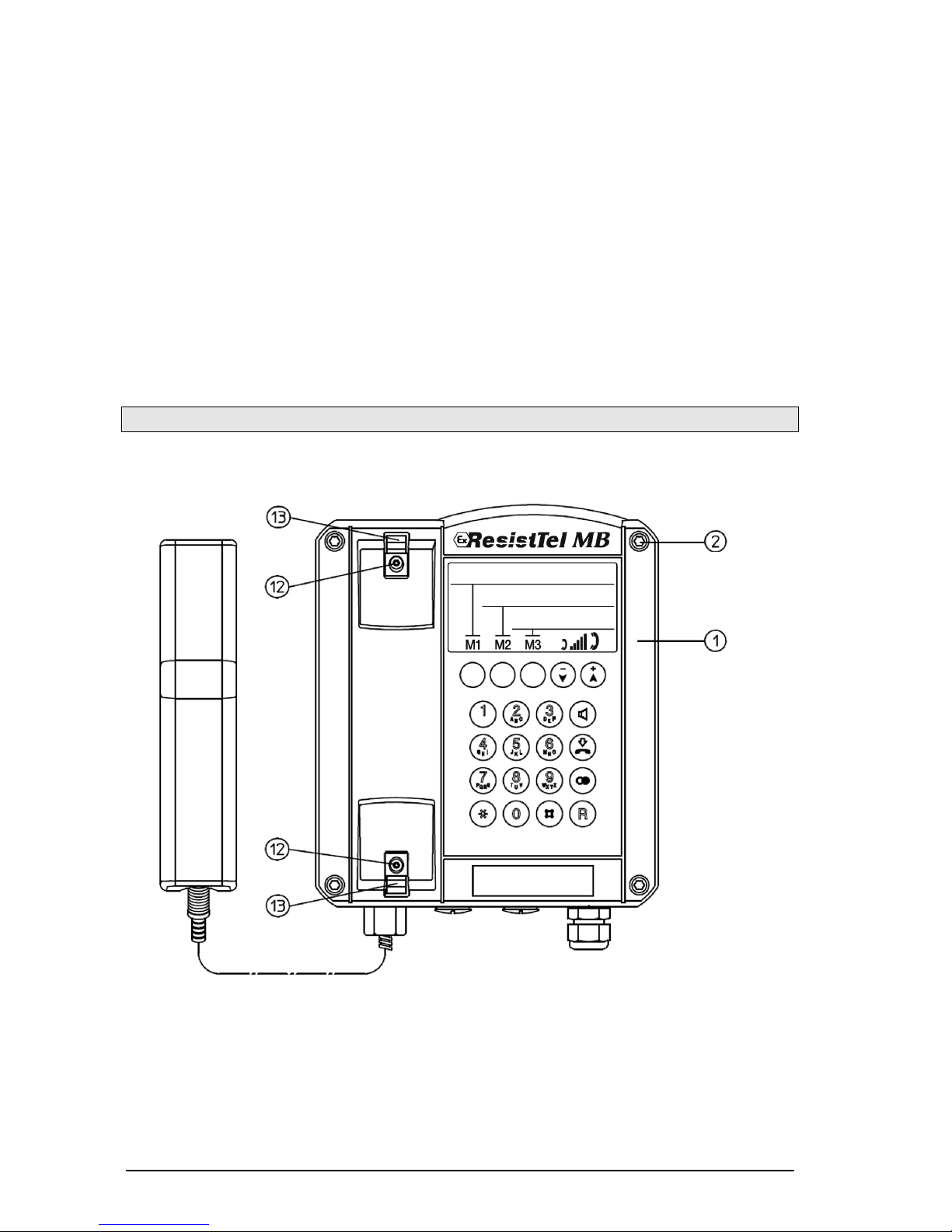
Device overview
(Cover screws)
(Top part of
the phone)
(Screws)
(Snap-in hook)

7
Device overview
Exterior view of the lower part of the phone
Interior view of the upper part of the phone
(Screws)
(Hook)
(Top part of
the phone)
(Top part of
the phone)
(Pin
header)

8
Device overview
Interior view of the lower part of the phone
…
No images needed here.
Keypad
(Speaker cable)
(Reed contact
cable)
(Sealing plug)
(Cable gland)
(Sealing plug)
(Screws)
(Lower part
of the phone)
(Keypad
connector)
(Programming
interface)

9
Keypad
Package contents
The package contains:
-Telephones ExResistTel MB
-Operating instructions ExResistTel MB
-Operating instructions cable entry
-EU declaration of conformity (ATEX)
-2 sticky label panels
-MB sticker
Label field
Volume settings buttons for
setting the volume of the handset,
speaker (hands-free and open
conversation) and headset during
the conversation
Speed dialling
button
Loudspeaker button
Disconnect button
Redial button
Second call button
Numeric keys

10
Explosion protection - device description
The ExResistTel MB serves for making calls within operating facilities in
danger of explosion in the zones: Zone 1, Zone 2, Zone 21 and Zone 22.
The ExResistTel MB telephone is designated to analogue telephone
networks.
The headset, second receiver and external secondary alarm
accessories are not a component of the ExResistTel MB telephone, but
rather can be connected as an option.
The ExResistTel MB telephone has an casing made of electrical-static,
conductive press plant material and a stainless steel keyboard.
The casing consists of a box shaped lower part, in which a tub is
integrated to hold the electronic system, as well as a curved cover with
a keyboard.
The cover is pressed under the medium layer of a surrounding seal with
four screws on the casing lower part and forms the non-secure and
secure connection space. The electronic system conductor board is
located in the tub from the casing lower part, which is completely
embedded in the compound.
Non-secure connection clamps with increased security:
From the casting, a 4-pin connection clamp (See connection diagram on
page 16) comes out in increased security, to connect the non-secure
telephone network (A, B), clamp 13 and 14 as well as for the connection
for an optional, external, explosion protected second alarm (Bell shunt1,
Bell shunt), clamp 15 an 16.

11
Secure connection clamps:
From the casting, a secure connection clamp series (see connection
diagram on page 16) comes out to connect the receiver integrated in the
telephone casing, clamps 1 to 4, as well as the secure accessories,
clamps 5 to 10.
The clamps 7 and 8 are intended for the connection of dynamic
earphones, as used in second receiver and headsets. This output is
therefore optionally used to connect a second receive or a headset, this
means second receivers and headsets cannot be connected
simultaneously as accessories.
Clamp
Note
Usage
1
Dynamic earphone connection 1
Earphone ear piece
2
Dynamic earphone connection 2
3
Electret microphone connection (+)
Earpiece microphone
4
Electret microphone connection (-)
5
Electret microphone connection (+)
Headset microphone
6
Electret microphone connection (-)
7
Dynamic earphone connection 1
Headset or second
receiver earphone
8
Dynamic earphone connection 2
9
Bridges between the clamps 9 and
10 recognize the telephone as a
connected headset
Headset recognition
10
To connect the accessory, the blank plugs installed in the telephone
casing are to be exchanged through suitable explosion protected cable
and line guides (M20x1.5).
Before connecting intrinsically safe accessories, and if a system
certificate for the intended connection does not exist, the constructor
should perform an evaluation of the intrinsic safety according to
EN 60079-25.
The technical data for the evaluation of the intrinsic safety can be found
in the chapter “Characteristic data”.
Further information see EN 60079-14.
A metal bracket is supplied for hanging up the intrinsically safe second
earpiece or headset. The metal bracket should be attached to the
telephone by means of the two threaded bushes in the floor of the
telephone housing. The corresponding bores in the metal bracket can
be used to screw the bracket securely onto to the housing floor (see
overview of the device on page 6). Thus, if the constructor wants to use

12
the metal bracket, the first thing he has to do, is to fix it to the housing
floor. Subsequently, the device may be mounted on the wall.
Secure program interface
From the cast, an 8-pin, secure connecting plug comes out (14) (see
device overview on page 8). It is only used by the manufacturer for
programming purposes. The connecting plug is to be left blank.
Programming through the raiser is not permissible.
Secure strand connection to the installed speaker
From the casting, a secure 2-pin strand line (16) (see device overview
on page 8), guided to the installed speaker. It is soldered under casting
and on the speaker.
Secure strand connection to the reed contact
From the casting, a secure 2-pin strand line (17) (see device overview
on page 8) led to a board, on which a magnet contact (reed contact) is
found. It is soldered under casting and on the conductor board with the
magnet contact.
Secure keyboard connection
From the casting, a secure 14-pin flat band line with connector is guided
through (7) (see device overview on page 8)
This connector should be placed on the 14 pin pin in the casing cover
before the device is screwed down.
.

13
Characteristic data
1. Non-secure power circuits
1.1 Telephone network
(Clamps A/B no.: 13 – 14)
Maximum input voltage Um(call voltage) AC 90 V
Permissible frequency range 16...54 Hz
or
Maximum input voltage Um(supply voltage) DC 66 V
Maximum input rated current 100 mA
Maximum input short circuit current IK35 A
(In the input of this device is a fuse
with a disconnect threshold of 35 A.)
1.2 External second alarm: only for the connection to passive
conductors
(Clamps Bell shunt1, Bell shunt no.: 15 –16)
Maximum call voltage AC 90 V
Frequency range 16...54 Hz
or
Maximum supply voltage DC 66 V
2. Secured Circuits
2.1 Headset (microphone)
(Clamp pair HSM no.: 5 – 6)
Maximum output voltage Uo17 V
Maximum output current Io90 mA
Maximum output rating Po80 mW
Maximum external capacity Co375 nF
Maximum external inductance Lo1,2 mH
2.2 Headset (earphone) or second receiver
(Clamp pair HSR No.: 7 – 8)
Maximum output voltage Uo17 V
Maximum output current Io110 mA
Maximum output rating Po190 mW
Maximum external capacity Co375 nF
Maximum external inductance Lo1,2 mH

14
2.3 Headset (recognition)
(Clamp pair HSS No.: 9 – 10)
Maximum output voltage Uo17 V
Maximum output current Io8 mA
Maximum output rating Po33 mW
Maximum external capacity Co375 nF
Maximum external inductance Lo100 mH
2.4 All secure output circuits have a linear output response curve.
3. Ambient temperature range
-25°C < Ta < 60°C for the temperature class T5
-25°C < Ta < 40°C for the temperature class T6
Identification
DMT 02 ATEX E 183 IECEx BVS 11.0033
F-No. ................... Insp. ................ Ik 35A IP66 IK09
Art.-No. ....................... Um = AC 90V / Um = DC 66V

15
Assembly and installation
The device can be installed only on a solid and vertical wall. Loosen the
screws of the cover (2) (see the overview of the device on page 6 to 8)
and take off the top part of the phone (1). When using the optional
accessories: headset or second headset, mount the hook (10) with two
screws (11) on the rear side of the lower part of the phone (In case of
the above accessories, the hook and the screws and also in case of all
optional accessories the cable gland is included in the respective
package). Insert four screws with a head diameter of 10 to 13 cm in the
opening (20) and mount the lower part of the phone (3) on the wall or a
panel.
The telephone network cable should be passed through the cable entry
(4) and connected to terminals 13 and 14 (A, B) in accordance with the
connection diagram.
In case of factory fitted cable glands the attached operating instructions
have to be considered.
On the telephone with a sealing plug or a 1/2” NPT metal adapter, the
customer is responsible for mounting a cable entry. Follow the
manufacturer’s operating instructions supplied with the cable entry
assembly. Only cable entries with EU type approval for IP66 enclosure
protection rating and -25°C ≤Ta ≤60°C should be used and they should
provide a good seal and fit tightly to the cable. If a torque of more than
20 Nm is used to tighten down the sealing rings of the cable entry, then
the side of the cable entry assembly nearest the housing should be
secured against rotating.
Prior to assembly, check cover seal for tightness.
Using the plug connector (7), plug the ribbon cable onto the pin contact
strip (8) in the upper part of the housing.
Attach the upper part of the telephone and fasten it to the lower part of
the telephone with the four cover screws (2).
The locking torque of the upper part screws is: 1.2 ... 1.5 Nm.
Regarding the assembly and installation please observe the respectively
applicable installations regulations.

16
Connection diagram
!
!
Support hook
The support force for holding the handset is infinitely adjustable.
Loosen the screws (12) and slide the snap-in hook (13). If you slide the
snap-in hook together, the support force increases, if you slide them
apart, the force decreases. Tighten the screws again.
Handset
Second
earpiece
Telephone-network
External second ringer
ye
gn
wh
br
Headset

17
Hole pattern
Please use the following dimensions (in millimetre) for making a drilling
template:
The diameter of the hole depends on the screws used (max. screw
diameter 8 mm) and the type of the surface (steel, wood, concrete,
sheetrock etc.) and please select accordingly.
Putting into service
The ExResistTel MB phone is ready for operation immediately after
connecting it to the network.
Maintenance
The ExResistTel MB phone does not contain any components requiring
maintenance.
18
Handset operation
If you lift the handset, the phone starts in handset mode. You can
modify the handset volume for the conversation using the and
buttons. For a permanent modification of the handset volume, please
access the configuration of the phone (see page 22). You can switch to
open listening with the button. Hold down the button and put the
handset back to switch to hands-free mode.
Open listening
You can modify the volume for open listening using the and
buttons. For a permanent modification of the speaker volume, please
access the configuration of the phone (see page 22). The handset
volume cannot be modified in open listening mode. You can switch to
handset mode with the button. Hold down the button and put the
handset back to switch to hands-free mode.
Hands-free mode
If you turn on the ExResistTel MB phone with the button, it starts up
in hands-free mode. You can modify the speaker volume of the
conversation using the and buttons. For a permanent
modification of the speaker volume, please access the configuration of
the phone (see page 22). You can end the conversation with the
button. If you lift the handset, the phone switches to handset mode.
19
Using the headset
If the headset is connected, the phone switches from open conversation
to headset mode. Open conversation is therefore not possible with the
headset. If you turn on the ExResistTel MB phone with the button, it
starts up in headset mode. If you lift the handset in the headset mode,
the handset is given priority. This means that you can listen and speak
using the handset, and you can only listen with the headset.
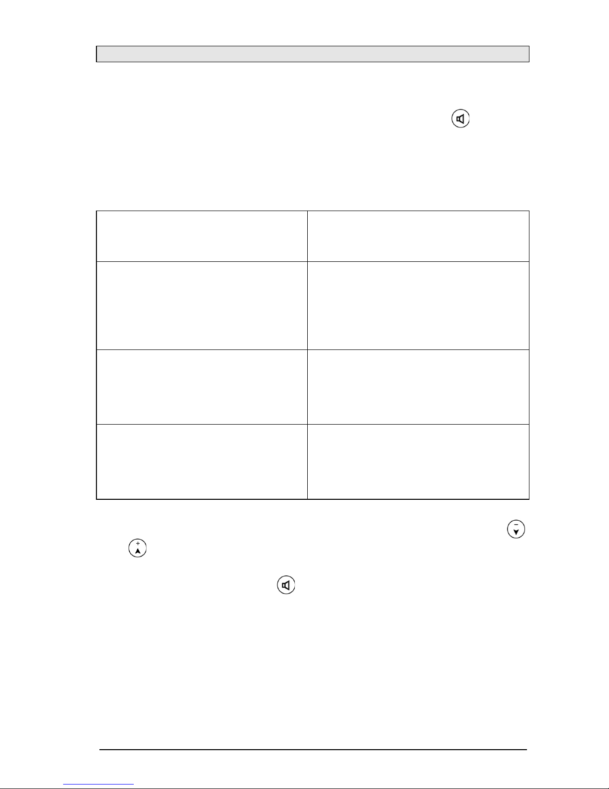
Compare the operation without and with the headset connected:
Operation without the headset
Operation with the headset
Handset operation
Handset operation with the
headset
- Handset is used for speaking and
listening
- headset is used for listening only
- Speaker is turned off
Open listening
Open listening with the headset
- Handset is used for speaking and
listening
- headset is used for listening only
- Speaker is turned on
Hands-free mode
Headset mode
- Handset is placed back
- headset is used for speaking
and listening
- Speaker is turned off
You can modify the headset volume of the conversation using the
and buttons. For a permanent modification of the headset volume,
please access the configuration of the phone (see page 22). You can
end the conversation with the button.
You can specify the operation of the ExResistTel MB phone after
disconnecting the headset in the configuration.

20
Operation
Receiving calls
Calls received are indicated with acoustic signals of the built-in speaker.
If the external speaker is connected and activated, the external speaker
is used for acoustic signalling. Lift the handset to establish the
connection with the caller. For activating the hands-free mode or
headset mode press the speaker button instead.
Making a call
Lift the handset, and you can hear the dial tone (dial ready tone) of the
public network or of the PBX network respectively.
Press the speed dialling button or the redial button or use the numeric
keys to select the phone number of the other party automatically or
manually.
Instead of lifting the handset, you can press the speaker button to make
a call in open conversation or headset mode.
For selecting a new phone number, you do not need to place the
handset back, you can press the disconnect button. The present
conversation is ended and you can hear the dial tone to select a new
phone number.
Redialling
If you press the redial button, the phone selects the last phone number
dialled after lifting the handset or pressing the speaker button.
Making a second call
During the conversation, you can disconnect and place the present
conversation on hold to make a second call with a different party. Press
the second call button and you will hear the dial tone. Dial the phone
number of the second party. After ending the second call, you can return
to the first call on hold by pressing the second call button again. You
can also connect the two parties of the first and second call with each
other: Place the handset back or press the speaker button in hands-free
or headset mode.
Making a second call is an additional service of the network operator or
of the PBX you use.
Operation with active phone lock
In case of active phone lock the dialling is limited or completely blocked.
If the blocked keys are still pressed, the phone generates the signal
“error tone”.
Table of contents
Other FHF Telephone manuals


