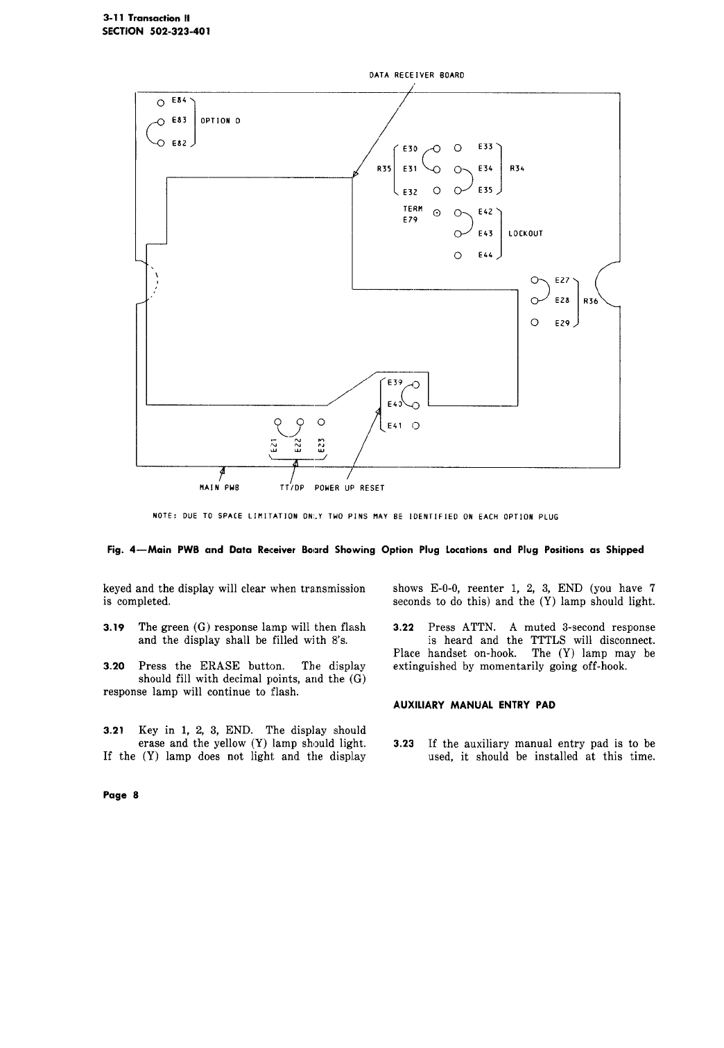
.06 It is recommended that at this time the set
should be opened up (3.07) and all option
lugs on main printed wiring board (PWB) and
ontrol board checked to insure that they are in
heir "when shipped" positions as shown by Tables
and D or Fig. 4 and 5. Check wiring terminations
nd if any loose connections are found, reterminate
er Fig. 11.
.07 To open set in order to access option plugs
and/or terminals proceed as follows:
(1) Disconnect power plug from AC outlet, if
connected.
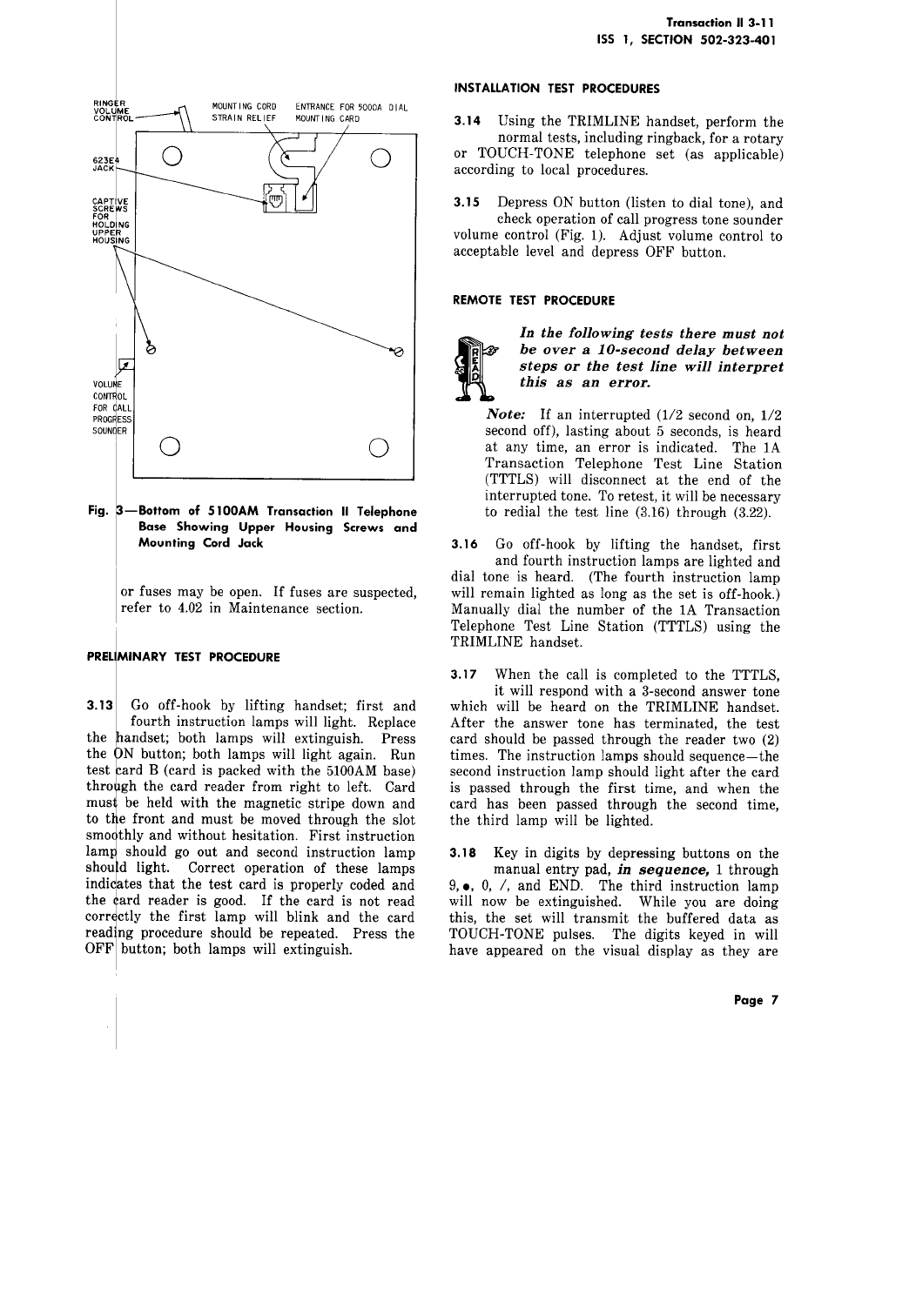
(2) Invert set and loosen the two captive screws
holding the upper housing and chassis (Fig.
3).
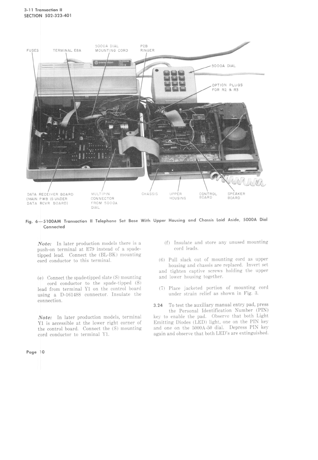
(3) Lay the upper housing and chassis to the
right, as shown by Fig. 6,without disconnecting
any cables.
(4) To reassemble, reverse procedure.
.08 Set the TOUCH-TONE signal output level
for the actual measured loss of the loop
3.05) as follows:
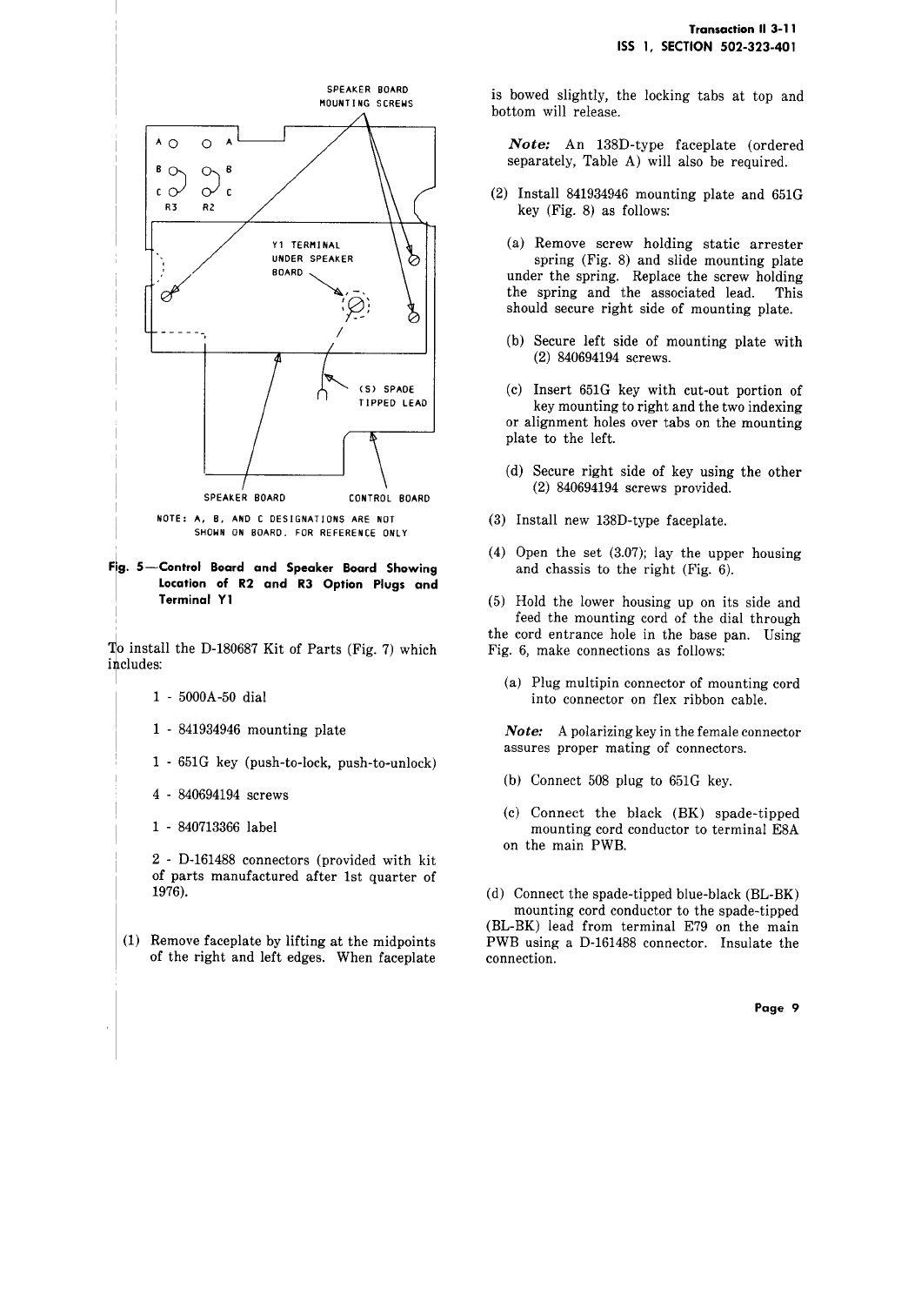
(1) Place the options on their proper positions.
See Fig. 4 and Table C.
(2) If the loss of the loop is 3.9 dB, or less,
resistors R2 and R3 on the control board
should be placed in the circuit. This is done
by moving the option pins from B-C to A-B as
shown by Fig. 5.
(3) If loss of loop exceeds 12 dB the quality of
the service may be impaired. Defer, according
to local procedures, until an acceptable loop is
made available.
.09 Connect the set to the telephone line by
inserting the mounting cord into the connecting
lock.
.10 Remove the gum-backed "OPTIONS" sticker
which is packed with the base and attach
the bottom of the base near the front. If
he service order does not call for the implementation
f any options (Dial Pulse, Lockout, or disconnection
f the ringer) at this time, reassemble set and
roceed to 3.12.
TransactionII 3-11
155 1, SECTION 502-323-401
Note: If the order calls for making dial of
hand telephone set inoperable, do not disable
dial until all testing is completed.
OPTIONS
3.11 If the service order specifies that the Dial
Pulse and/or Lockout options be activated,
or that ringer be disconnected, access the main
PWB (3.07) and proceed as follows:
(a) If both Dial Pulse and Lockout options are
called for:
(1) Place TT/DP option plug for DP per Table
D.
(2) Place upper housing and chassis back on
set and reconnect AC power cor_d.
(3) Go off-hook and, using manual entry pad,
dial any test number and verify that the
call is completed. This tests the dial pulse
feature .
(4) Disconnect power cord, lay upper housing
and chassis aside, and move Lockout
option plug to lockout position per Table D.
(5) Reassemble set and reconnect AC power
cord.
(6) Test lockout by going off-hook and
depressing any button on manual entry
pad to verify absence of TOUCH-TONE
frequency signals.
(b) If only Dial Pulse option is specified:
(1) Proceed as in (a) Steps (1), (2), (3) and
(5).
(c) If only Lockout option is specified:
(1) Move Lockout option plug per Table D.
(2) Reassemble set and reconnect AC power
cord.
(3) Test lockout by going off-hook and
depressing any button on manual entry
pad to verify absence of TOUCH-TONE
frequency signals.
Page 5