Fike 313-0001 Sita Soundpoint User manual

26-0190 Issue 9
General Description
The Sita Soundpoint unit allows for audible indication when the system enters an alarm
condition. This is an addressable unit that attaches to the loop. Digital communication
technology to the control panel is implemented allowing for accurate data transfer at high
transmission speeds. This device is only compatible with the Sita200plus, Duonet and
Quadnet ranges of control panels.
Before Installation
The sounder must be installed in compliance with the control panel installation
manual. The installation must also meet the requirements of any local authority. For
maximum performance the sounder should be installed in compliance to BS5839
Pt1 : 2002 + A2 : 2008.
Spacing
Fike recommends spacing of sounders in accordance with BS5839 Pt1. For more
specific information regarding sounder spacing, placement and special applications
please refer to BS5839 Pt1 : 2002 + A2 : 2008.
Device Installation
All wiring must be installed in compliance with the recommendations laid out by BS 5839 as well as any special
recommendations documented in the control panel installation manual. The cabling used should be of a 2-core
1.5mm2screened, fire resistant type, with the following characteristics:
Max Capacitance Core to Screen................................................... 180pF / m
Max Capacitance Core to Core ...................................................... 100pF / m
Max Inductance .............................................................................. 1.0mH / km
Max Resistance Two Core Screened 1.5mm²................................ 12.1Ω/ km
It is to be wired in the form of a screened 2-core loop returning to the control panel. The use of spurs on
this system is not permitted.
Fix the surface back box to a flat vertical surface using at least two of the four mounting holes provided. The back
box may be drilled to allow cable access as required. A 20mm hole is already provided at the rear. Cables may be
terminated into the connectors, as shown below.
The Soundpoint may be flush mounted utilising the optional adaptor plate, combined with any standard single gang
flush mounting back box (with a minimum internal depth of 47mm). After installing the back box securely, attach the
adaptor plate using the two screws provided and terminate the loop cables directly into a flying terminal block (not
supplied).
Care should be taken when terminating devices to ensure all cables are correctly sleeved and connections are
secure. Improper connections will prevent a system from responding properly in the event of a fire.
Terminal Description
RED Loop +ve IN
YELLOW Loop +ve OUT
BLUE Loop -ve IN and OUT
E Screen IN and OUT
INSTALLATION AND MAINTENANCE INSTRUCTIONS
313-0001 Sita Soundpoint, Red
313-0002 Sita Soundpoint, White
E

26-0190 Issue 9
The Loop +ve (positive) IN and the Loop +ve (positive) OUT connections are split within the module, for cable
continuity readings at the commissioning stage they must be temporarily removed and connected through. Please
remember that all high voltage testing must be carried out before the installation of the electronics, otherwise the
electronics will be damaged. Please also note that the E terminal should only be connected to the loop screen and
NOT to the building earth.
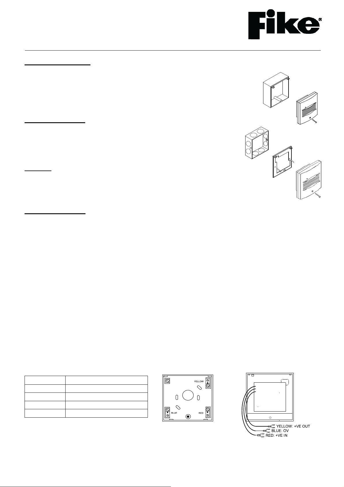
Once all testing has been carried out on the cabling and continuity & insulation has been proven, the sounder
can be connected, with each of the three wires from the Soundpoint front being connected to the corresponding
terminal in the backbox according to the wire colour. The Soundpoint front may then be installed by locating the
upper mounting hooks into the receivers in the back box and then pushing the unit gently home. The single fixing
screw may then be tightened as required.
If the device is flush mounted then the loop cabling must be attached to the device via a suitable connection block
(not supplied). Cut off crimp fork terminals, strip ends for desired length and twist conductor strands together
neatly. Terminate your cables directly into a flying terminal block. If using a metal back box, do not connect the
screen to the back box earth terminal or allow it to come into contact with the metal box
NOTE: Before installing the sounder remember to note the serial number of the device (located on the rear of the
unit) on to your drawings or configuration sheets to enable you to prove its location later. The address allocation for
the device is carried out automatically by the control panel whilst in initialisation mode, so addresses do not need to
be set manually. See the system Installation and Operating Instructions for further details.
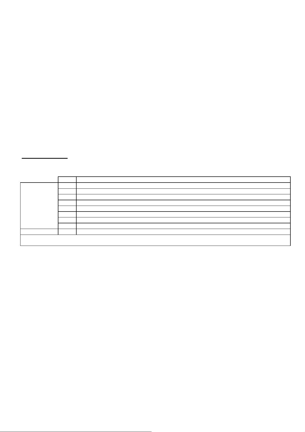
Device Settings
The sounder modes may be configured using the relevant panel software configuration package (OSP).
Type Description
Sound Pattern: SP0 Sounder off
SP1 Single tone, 970 Hz continuous
SP2 Pulsed UK alert signal, 970 Hz 1s on, 1s off
SP3 Dual tone UK evacuate signal, 970 Hz 0.25s, 800 Hz 0.25s
SP4 Sweep up, 800 Hz to 970 Hz over 1s
SP5 Slow whoop up, 500 to 1200 Hz over 3s, 0.5s off
SP6 Sweep down, 1200 Hz to 500 Hz over 1s
SP7 Dual tone French warble, 550 Hz 0.1s, 440 Hz 400ms
Sound Volume: L/M/H Low, medium and high settings are available.
See the Engineering & Commissioning Manual for your control panel (Sita, Duonet or Quadnet) for further details of how to
program the above.

26-0190 Issue 9
Technical Data
Dimensions: Width x Height 89mm x 89mm
Depth: Standard inc base 62mm
Depth: Flush mounted 34mm
Flush Back Box Dimensions: Required Minimum Depth 47mm
Operating Temperature: -10
oC to +50oC.
Voltage Range (Loop): 24 to 42V DC
Flammability: UL94-V2
IPRating: IP 21C
System Compatibility: Sita200plus V2.30 onwards.
Duonet and Quadnet V1 onwards.
PRODUCT DESCRIPTION VOLUME LEVEL (dBA)
Type Product
Code Name Low Medium High
SNDR 313 0001
313 0002
Sita Soundpoint Mk3 (Red)
Sita Soundpoint Mk3 (White) 65+ 80 85
LOOP CURRENT (mA)
Type Product
Code Name Quiescent SP0 - Off Low Medium High
SNDR 313 0001
313 0002
Sita Soundpoint Mk3 (Red)
Sita Soundpoint Mk3 (White) 0.18 - 1.74 3.87 5.39
BATTERY CURRENT (mA)
Type Product
Code Name Quiescent SP0 - Off Low Medium High
SNDR 313 0001
313 0002
Sita Soundpoint Mk3 (Red)
Sita Soundpoint Mk3 (White) 0.18 - 3.62 8.05 11.22
DLU RATING
Type Product
Code Name SP0 - Off Low Medium High
SNDR 313 0001
313 0002
Sita Soundpoint Mk3 (Red)
Sita Soundpoint Mk3 (White) - 2 4 5.5
N.B. All specified volume and current readings, unless otherwise stated are taken using sound pattern SP3.

26-0190 Issue 9
0832
Fike Safety Technology Ltd,
31 Springvale Ind Est,
Cwmbran, UK. NP44 5BD
(Manufactured Date on Product Label)
0832-CPD-1584
EN54-3 Fire Alarm Device – Sounder
Type A – Indoor Use
EN54-17 Fire Alarm Device – Isolator
Sounder Technical Data: See 26-0747
Isolator Technical Data: See 26-1112
Technical Support
Contact your supplier for technical support on this product.
Due to the complexity and inherent importance of a life risk type
system, training on this equipment is essential, and commissioning
should only be carried out by competent persons. Fike cannot
guarantee the operation of any equipment unless all documented
instructions are complied with, without variation. This unit complies
with the EMC directive.
Fike’s policy is one of continual improvement and the right to change a
specification at any time without notice is reserved. Whilst every care
has been taken to ensure that the contents of this document are
correct at time of publication, Fike shall be under no liability
whatsoever in res
p
ect of such contents. E&OE.
This manual suits for next models
3
Other Fike Fire Alarm manuals
Popular Fire Alarm manuals by other brands

Comelit
Comelit 41CPE118 Technical manual

National Security Systems
National Security Systems All-Safe 4 Zone P.A. SYSTEM instruction manual

ESP
ESP MAGPRO-WSS23 Installation instruction

Teletek electronics
Teletek electronics SensoIRIS T110 IS Installation instruction

Bosch
Bosch FPA-5000 Networking guide

Simplex
Simplex 2004 Series Operation guide