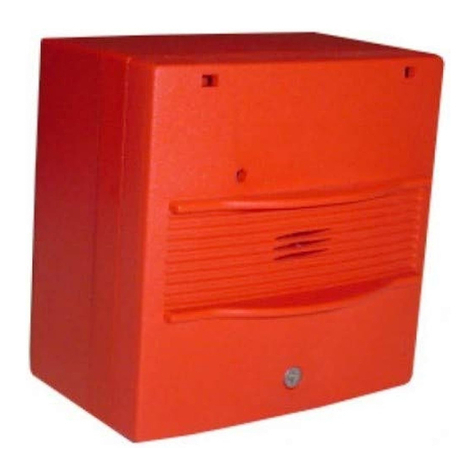
Fike Sita User manual

26-1046 Issue 4
General Description
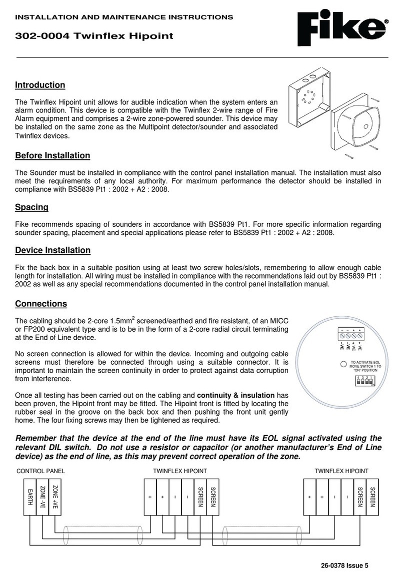
The Sita Sounder unit allows for audible indication when the system enters an
alarm condition. This is an addressable unit that attaches to the loop. Digital
communication technology to the control panel is implemented allowing for
accurate data transfer at high transmission speeds. This device is only
compatible with the Sita 200+, Duonet and Quadnet ranges of control panels.
Before Installation
The Sounder must be installed in compliance with the control panel
installation manual. The installation must also meet the requirements of any local authority. For maximum
performance the device should be installed in compliance with BS 5839 Pt1 : 2002 + A2 : 2008.
Spacing
Fike recommends spacing of sounders in accordance with BS 5839. For more specific information regarding
sounder spacing, placement and special applications please refer to BS 5839 Pt1 : 2002 + A2 : 2008.
Device Installation
Drill the cable entry region(s) in base moulding as required.
Drill out the desired mounting holes through hole / slot guides as required. Affix the base moulding to a flat surface
using a minimum of 2 screws.
All wiring must be installed in compliance with the recommendations laid out by BS 5839 as well as any special
recommendations documented in the control panel installation manual. The cabling used should be of a 2-core
1.5mm2screened, fire resistant type, with the following characteristics:
Max Capacitance Core to Screen...................................................180pF / m
Max Capacitance Core to Core.......................................................100pF / m
Max Inductance...............................................................................1.0mH / km
Max Resistance Two Core Screened 1.5mm²................................12.1Ω / km
It is to be wired in the form of a screened 2-core loop returning to the control panel. The use of spurs on
this system is not permitted. Cables may be terminated into the connector, as shown below. Care should be
taken when terminating devices to ensure all cables are correctly sleeved and connections are secure. Improper
connections will prevent a system from responding properly in the event of a fire.
Terminal
Description
L1
Loop +ve IN
0V
Loop -ve IN
SCRN
Screen IN
SCRN
Screen OUT
0V
Loop -ve OUT
L2
Loop +ve OUT
The Loop +ve (positive) IN and the Loop +ve (positive) OUT connections are split within the module. For cable
continuity readings at the commissioning stage they must be temporarily removed and connected through.
Please remember that all high voltage testing must be carried out before the installation of the electronics,
otherwise the electronics will be damaged. Please also note that the SCRN terminal should only be connected to
the loop screen and NOT the building earth.
INSTALLATION AND MAINTENANCE INSTRUCTIONS
326-0003 Sita Sounder with Deep Base
www.acornfiresecurity.com
www.acornfiresecurity.com

26-1046 Issue 4
Once all testing has been carried out on the cabling and continuity & insulation has been proven, the Sounder
can be connected.
NOTE: Before installing the Sounder remember to note the serial number of the device (located on the rear of the
unit) on to your drawings or configuration sheets to enable you to prove its location later. The address allocation for
the device is carried out automatically by the control panel whilst in initialisation mode, so addresses do not need to
be set manually. See the system Installation and Operating Instructions for further details.
Tamper Resistance
The unit incorporates a locking screw which helps prevent unauthorised removal from the base. To fit, gently insert
the device positioned so that the alignment mark on the rim is rotated slightly anti-clockwise relative to the
alignment mark on the base. Rotate clockwise until the device drops in and the alignment marks meet. Tighten the
locking screw, but do not over tighten.
To remove the device, unscrew the retaining screw. The device should then be turned anti-clockwise allowing it to
be removed from the base.
Device Settings
The sounder modes may be configured using the relevant panel software configuration package (OSP).
Type
Description
Sound Pattern:
SP0
Sounder off
SP1
Single tone, 970 Hz continuous
SP2
Pulsed UK alert signal, 970 Hz 1s on, 1s off
SP3
Dual tone UK evacuate signal, 970 Hz 0.25s, 800 Hz 0.25s
SP4
Sweep up, 800 Hz to 970 Hz over 1s
SP5
Slow whoop up, 500 to 1200 Hz over 3s, 0.5s off
SP6
Sweep down, 1200 Hz to 500 Hz over 1s
SP7
Dual tone French warble, 550 Hz 0.1s, 440 Hz 400ms
Sound Volume:
L/M/H
Low, medium and high settings are available
See the Engineering & Commissioning Manual for your control panel (Sita, Duonet or Quadnet) for further details of how to
program the above.
Technical Data
Dimensions: Diameter 97 mm
Depth: inc deep base 83 mm
Operating temperature: -10oC to +50oC.
Flammability: UL94-V2
IP Rating: IP21C
Voltage Range (Loop):24 to 42V DC
System Compatibility: Sita 200 plus V2.30 onwards.
Duonet and Quadnet V1 onwards.
PRODUCT DESCRIPTION
VOLUME LEVEL (dBA)
@ 1m anechoic (Dual Tone)
Type Product
Code Name Low Medium High
SNDR
326 0003
Sita Sounder with Deep Base
65+
84
88
LOOP CURRENT (mA)
Type Product
Code Name Quiescent SP0 - Off Low Medium High
SNDR
326 0003
Sita Sounder with Deep Base
0.18
1.31
1.73
3.86
5.37
www.acornfiresecurity.com
www.acornfiresecurity.com

26-1046 Issue 4
BATTERY CURRENT (mA)
Type Product
Code Name Quiescent SP0 - Off Low Medium High
SNDR
326 0003
Sita Sounder with Deep Base
0.18
2.74
3.62
8.04
11.18
DLU RATING
Type Product
Code Name SP0 - Off Low Medium High
SNDR
326 0003
Sita Sounder with Deep Base
1.5
2.0
4.0
5.5
N.B. All specified volume and current readings, unless otherwise stated are taken using sound pattern SP3.
0832
Nominal activation conditions/Sensitivity,
Response delay (response time) and
performance
under fire conditions
Pass
Operational reliability
Pass
Durability of operational reliability and
response delay, Temperature resistance
Pass
Durability of operational reliability, Vibration
resistance
Pass
Durability of operational reliability, Humidity
resistance
Pass
Durability of operational reliability, Corrosion
resistance
Pass
Durability of operational reliability, Electrical
stability
Pass
Performance under fire conditions
Pass
Durability of operational reliability, Resistance
to ingress
Pass
Technical Support
Contact your supplier for technical support on this
product.
Due to the complexity and inherent importance of a life
risk type system, training on this equipment is essential,
and commissioning should only be
carried out by
competent persons. Fike cannot guarantee the operation
of any equipment unless all documented instructions are
complied with, without variation. This unit complies with
the EMC directive.
Fike’s policy is one of continual improvement and the
right to change a specification at any time without notice
is reserved. Whilst every care has been taken to ensure
that the contents of this document are correct at time of
publication, Fike shall be under no liability whatsoever in
respect of such contents. E&OE.
EN54-3: 2001 +A1: 2002 +A2: 2006, EN54-17: 2005
Sounder Technical Data: See 26-0747
Isolator Technical Data: See 26-1112
326-0001, 326-0003
Intended for use in the fire detection and fire alarm
Systems in and around buildings
Essential characteristics Performance
www.acornfiresecurity.com
www.acornfiresecurity.com
This manual suits for next models
1
Other Fike Marine Equipment manuals


