Fike EPACO PSU E10-0067 Owner's manual

Manual P/N: E06-052
Rev. No: 9, 07/08
Power Supply Unit
E10-0067
Installation and Operation
Instructions


FM 3020541 Power Supply Unit Installation & Operation Instructions Page i
P/N E06-052 Rev. 9 07/08
Introduction
Fike is pleased to present a new Power Supply Unit
Manual for our EPACOExplosion Protection
System. This document has been created to
incorporate the most up-to-date information
available for this Fike product and to make it easy
to use.
Who should read this manual?
This manual is intended for those individuals who
are custodians of the Fike EPACOSystem.
Others such as architects, engineers, sales and
marketing personnel, etc. will find the information
useful as well.
.
Warranty Information
Fike provides a one-year limited manufacturer’s
warranty on the product identified in this manual.
Copies of the warranty can be obtained from an
authorized Fike sales outlet. An authorized Fike
sales outlet, using the MRA procedure, must return
warranty items. See Section 11 of this manual for
details of returning product to Fike.
Limitation of Liability
Fike Corporation cannot be held liable for any
damages resulting from the use or misuse of this
product.
Important Safety Instructions
(a) Save these instructions-this manual contains
important safety instructions.
(b) Caution: A battery can present a risk of electric
shock, burn from high short-circuit current –
observe proper precautions.
(c) When replacing the batteries, use the same
number and type of sealed-cell lead acid.
(d) Proper disposal of batteries is required. Refer
to your local code for disposal requirements.
Copyright, Trademark and Licensing
Notice
All Fike documentation and hardware are copyright
with all rights reserved. No part of this product may
be copied, reproduced or transmitted by any
mechanical, photographic, electronic or other
method without Fike’s prior written consent. Fike
product names are trademarked; other product
names, as applicable, are trademarks of their
respective holders.
Disclaimer
The information contained in this manual is as
accurate as possible. This manual is intended to
be an aid to Fike EPACOSystem users. Fike
does not warrant that this manual is technically
correct, complete or the product referenced herein
is free from minor flaws. Fike reserves the right to
change the information contained in this manual
without notice.
Quality Notice
Fike Corporation has maintained ISO 9001
certification since 1996. Prior to shipment, we
thoroughly test our products and review our
documentation to assure the highest quality in all
respects. In a spirit of continuous improvement,
Fike welcomes your suggestions. Please direct all
suggestions or comments to
Fike Blue Springs Product Support
Phone: +1-800-979-FIKE Ext.2-3
(3453)
Fax: +1-816-229-0314
or
Fike Europe Product Support
Phone: +32-14-21-00-31
Fax: +32-14-21-07-43
Any suggestions or comments become the property
of Fike Corporation.

Page ii Power Supply Unit Installation & Operation Instructions FM 3020541
07/08 P/N E06-052 Rev. 9
This page intentionally left blank.

FM 3020541 Power Supply Unit Installation & Operation Instructions Page iii
P/N E06-052 Rev. 9 07/08
TABLE OF CONTENTS
1.0 Terms and Symbols Used In This Manual............................................................................................ 1
2.0 EPACO System Overview ...................................................................................................................... 2
3.0 System Components .............................................................................................................................. 3
4.0 Installation ............................................................................................................................................... 4
4.1 Installation Overview............................................................................................................................. 4
4.2 Power Specifications............................................................................................................................. 4
4.3 Power Supply Unit (PSU)...................................................................................................................... 5
4.4 Inputs .................................................................................................................................................... 6
4.4.1 AC Power Supply (P3) ................................................................................................................... 6
4.4.2 Battery Input (P4)........................................................................................................................... 6
4.5 Outputs.................................................................................................................................................. 6
4.5.1 Trouble Relay (P5)......................................................................................................................... 6
4.5.2 24VDC Outputs Wiring Size (P2)................................................................................................... 7
4.5.3 Status Bus Connection (P1) .......................................................................................................... 8
5.0 Operation ................................................................................................................................................. 9
5.1 Startup................................................................................................................................................... 9
5.2 Normal operation .................................................................................................................................. 9
5.3 AC power .............................................................................................................................................. 9
5.4 Output power....................................................................................................................................... 10
5.5 Battery power ...................................................................................................................................... 10
5.6 Output lines (1-5) ................................................................................................................................ 10
5.7 Status bus communication.................................................................................................................. 10
5.8 History ................................................................................................................................................. 11
6.0 Periodic Maintenance........................................................................................................................... 12
6.1 General ............................................................................................................................................... 12
6.2 Inspection Procedure .......................................................................................................................... 12
6.3 Routine Inspections ............................................................................................................................ 12
6.4 Three-Year Replacement.................................................................................................................... 12
6.5 Ten-Year Replacement....................................................................................................................... 12
7.0 DeCommissioning Procedure / Check-List........................................................................................ 13
8.0 Spare parts ............................................................................................................................................ 14
9.0 Diagnostics............................................................................................................................................ 15
9.1 LED Diagnostics ................................................................................................................................. 15
9.2 Voltage Chart ...................................................................................................................................... 16
10.0 Specifications........................................................................................................................................ 17
11.0 Repair and Return Authorization ........................................................................................................ 18
ANNEX A Battery Calculations...................................................................................................................... 20

Page iv Power Supply Unit Installation & Operation Instructions FM 3020541
07/08 P/N E06-052 Rev. 9
LIST OF EXHIBITS
Exhibit 2-1 EPACO System Block Diagram........................................................................................................ 2
Exhibit 3-1 PSU Photo ........................................................................................................................................ 3
Exhibit 4-1 PSU Block Diagram.......................................................................................................................... 5
Exhibit 4-2 PSU Bottom View – P3-P5 Wiring Connections .............................................................................. 6
Exhibit 4-3 AC Power Input ................................................................................................................................ 6
Exhibit 4-4 Battery Input ..................................................................................................................................... 6
Exhibit 4-5 Trouble Relay Output ....................................................................................................................... 6
Exhibit 4-6 PSU Top View – P1-P2 Wiring Connections.................................................................................... 7
Exhibit 4-7 24VDC outputs ................................................................................................................................. 7
Exhibit 4-8 Maximum Circuit Resistance ............................................................................................................ 7
Exhibit 4-9 Conductor Properties........................................................................................................................ 7
Exhibit 4-10 Status Bus Wiring ........................................................................................................................... 8
Exhibit 5-1 Status LEDs...................................................................................................................................... 9
Exhibit 5-2 Output Lines ................................................................................................................................... 10
Exhibit 5-3 History Codes ................................................................................................................................. 11
Exhibit 7-1 Decommissioning Steps ................................................................................................................. 13
Exhibit 8-1 PSU Spare Parts List...................................................................................................................... 14
Exhibit 9-1 PSU LED Diagnostics..................................................................................................................... 15
Exhibit 9-2 PSU Voltages ................................................................................................................................. 16

FM 3020541 Power Supply Unit Installation & Operation Instructions Page 1 of 21
P/N E06-052 Rev. 9 07/08
1.0 TERMS AND SYMBOLS USED IN THIS MANUAL
Term/Symbol Description
Trouble symbol. This symbol is on the face of the PSU next to the yellow trouble
LED. This LED will ill
uminate on any trouble condition where the PSU’s
monitoring system is indicating a fault in one or more of its systems.
25VAC
AC Power
symbol. This symbol is on the face of the PSU with an LED next to it.
The LED will be green when the input voltage is within proper tolerance. This
symbol is also located on the bottom of the PSU next to the P3 terminal. This
designates the 25VAC input (primary power) wiring connection location.
24VDC
DC Power symbol. This symbol is on the face of the PSU next to the LED. This
LED illuminates green in a normal state to indicate that the unit is receiving
backup battery power. This system is also located on the bottom of the PSU next
to the P4 terminal. This designates the 24VDC input (secondary power) wiring
connection location.
OUTPUT
VOLTAGE
Output Voltage
symbol. This symbol is on the face of the PSU next to its LED.
When the output power is within tolerance, the LED will be green.
Fuse symbol. This designation represents a circuit protection fuse. The fuse is
rated at the amperage noted next to this marking.
DB9
Computer Connection symbol. This designation represents the location for the
computer connection. Using a straight-
through serial cable, the PSU can be
connected from this DB9 connection to a computer serial port. The EP Works
software can be installed on the computer and provide operational information.
Status Bus symbol. This circuit is a low speed network connection that sends
status information to the Annunciator Module.
DC Power symbol. This symbol is located on the PSU P2 terminal outputs. It
designates the 24VDC output available for po
wering four Explosion Protection
Controllers (EPCs), one Annunciator Module (AM), and one Relay Control Module
(RC8).
NO NC C
Trouble Relay
symbol. This symbol located on the bottom of the PSU at P5
terminal outputs. It designates the relay output wiring connections.

Page 2 of 20 Power Supply Unit Installation & Operation Instructions FM 3020541
07/08 P/N E06-052 Rev. 9
2.0 EPACO SYSTEM OVERVIEW
The EPACOSystem is a modular detection and
control system combining the latest in addressable
technology with simplicity of installation and
maintenance. All system modules are DIN rail
mounted to allow for a variety of installation options.
Three (3) bus type communication circuits tie the
various system modules into one easy to operate
protection system. A non-volatile history buffer allows
for enhanced diagnostic ability to troubleshoot process
situations. With the optional
Annunciator Module (AM), the customer has the
ability to step through a menu format to retrieve
process history without having to wait for a service
agency to arrive on site.
This manual will provide the necessary information
to properly install and monitor the Power Supply
Unit (PSU) for the EPACOSystem. The
commissioning and service should be performed
by certified service engineers and outlets
specifically trained on this system.
Exhibit 2-1 EPACO System Block Diagram
POWER
SUPPLY
UNIT
ANNUNCIATOR
MODULE
EXPLOSION
PROTECTION
CONTROLLER
RELAY
CONTROL 8
(8 RELAYS)
UP TO 6
RELEASING
DEVICES

FM 3020541 Power Supply Unit Installation & Operation Instructions Page 3 of 21
P/N E06-052 Rev. 9 07/08
3.0 SYSTEM COMPONENTS
The cornerstone of the system is the Explosion
Protection Controller (EPC). Three colored LEDs
provide instant visual indication of system status. The
DIN rail mounting allows for flexibility when choosing
an enclosure. The EPC is an addressable panel that
has the ability to retain an event history for enhanced
system diagnostics. The EPC is a component that
allows mounting in close proximity to the protected
environment, thereby minimizing field wiring. Shorter
wire runs greatly reduce the interference from
electrical and radio frequency sources, allowing for a
much more reliable protection system. The EPC’s
detection inputs can be programmed for pressure
warning, threshold detection, and rate of rise
detection. It also has a contact closure detection
circuit to support thermal, infrared, or other switch-
closure type detection devices1. A supervisory input
circuit is provided to monitor suppression container
pressure or other similar system status safeguards.
The EPC has a remote disable input contact to allow
for disabling the EPC from a customer PLC or other
remote device during product loading, cleaning, or
maintenance. DIP switches allow for basic system
programming. An RS232 connection is available at
each module for connection to a PC. Using the EP
WorksTM software, an authorized user can access
system diagnostics and more complex programming
by PC.
The EPC is powered by the other key component in
the EPACOsystem, the Power Supply Unit (PSU).
The PSU has six separate 24 VDC, 1 amp power
output circuits capable of powering up to four EPCs in
addition to other components of the EPACOsystem.
The PSU has the flexibility of containing its own
battery backup supply or the customer has the option
of supplying a backup power source. The PSU has an
imbedded power shutdown procedure in the event of
AC power failure, which prevents the backup batteries
from being completely depleted. In addition to
powering EPCs, the PSU can power an Annunciator
Module (AM) and Relay Card Modules (RC8). The
power circuit dedicated for the Annunciator Module
can not be shut off. All other power output circuits can
be shut off for service on the various system
components. The PSU may be eliminated if battery
backed, uninterrupted 24VDC, 2A power can be
provided by others. For an FM approved installation
without the PSU, the uninterruptible power must be
U.L. 1778 “Uninterruptible Power Systems” listed, and
conform to NFPA 72 “National Fire Alarm Code”,
1FM Approved switch closure for use with Fike threshold detector
(E61-042-x) and Rate of Rise detector (E61-056-x). Other switch
closure, thermal, or infrared devices are not approved by FM.
NFPA 70 “National Electrical Code” (Articles 700
and 701), NFPA 110 “Standard for Emergency
and Standby Power Systems”, and NFPA 111
“Standard on Stored Electrical Energy Emergency
and Standby Power Systems”.
The Annunciator Module (AM) provides a central
communication point for diagnostics. This module
will typically be installed in an area removed from
the process environment such as a control room.
The AM has two push buttons to access the
various menus and three numbered LEDs for
identification of the system statuses within the
menus.
The Relay Card Module (RC8) provides the user
with a block of eight form “C” relays for equipment
shutdowns and remote notification of system
trouble and alarm conditions. On-board LEDs
display status for instant visual verification of each
relay. DIP switches are provided for configuring
the relay’s operation.
Exhibit 3-1 PSU Photo

Page 4 of 20 Power Supply Unit Installation & Operation Instructions FM 3020541
07/08 P/N E06-052 Rev. 9
4.0 INSTALLATION
4.1 INSTALLATION OVERVIEW
The effectiveness of active explosion protection
systems, such as explosion suppression and
explosion isolation, depends upon the instantaneous
reaction of the protection system and is a direct
function of its speed of response.
It is therefore, critical that all possible measures are
taken to reduce the individual system components’
response times to an absolute minimum.
An active explosion protection system basically
consists of three components: One or more
explosion detectors, an electronic system controller,
and one or more protective devices such as
explosion suppressors or isolation valves.
Instrumentation wiring interconnects these
components.
The system controller is microprocessor-based and
shall be installed in a location that maintains the
EPC’s temperature rating of -18°C to 43°C (0°F to
110°F) when it is installed in an auxiliary housing.
For FM Approved installations the housing shall be a
lockable enclosure conforming to the installed area
requirements as defined by NEMA 250 “Enclosures
for Electrical Equipment (1000 Volts Maximum).”
Besides its function as a fire controller it also
incorporates an event table and a self-checking
feature to continuously monitor the complete
system-loop for errors or system defects.
Electronic devices, microprocessors, pyrotechnic
initiators, and field wiring are influenced by the
electromagnetic “environment” surrounding these
components. The use of cellular telephones,
transmitters, induction motors, welding equipment or
the presence of power cables and transformers can
create environments with high levels of
electromagnetic radiation, resulting in induced
electrical “noise” or voltage peaks.
Such effects are known to designers and
manufacturers of instrumentation and control
systems (PLC’s), used in industrial environments
and are handled through the use of specially
designed electronic filters. These filters neutralize
the unwanted noise and offer a “clean” signal for
further processing. The filters, however, result in a
delay in the processing of signals, and can therefore
only be applied with great care in explosion
protection systems where the effectiveness depends
on the overall response time.
In active explosion protection systems, a balance
must be maintained: The system must be extremely
fast to achieve the required effectiveness, but at the
same time must be stable and insensitive to
surrounding sources of noise.
The system controller will detect and report major
system troubles (such as ground faults, wire
disconnection, and unstable input or output signals)
and indicates the need for appropriate action.
The system controller will also detect unacceptable
levels of electromagnetically induced noise. If the
magnitude of the noise is such that this may result in
a risk for spontaneous system activation or affect the
system’s performance, the controller will revert to its
default error-mode.
It is essential to practice extreme caution when
selecting component location, cable specifications,
cable routes, and the “cleanliness” of the offered
power source. In order to reduce the
electromagnetic induced noise to a level that will not
affect the required performance of the explosion
protection system, verify all earth connections. It is
preferred to have the enclosure and conduits
connected to Protective Earth (similar with other
building grounds) while the drain wires from the field
wiring and each module ground connected to a
separate Instrument Earth. This Instrument Earth
connection shall not have inductive or capacitive
loading such as motors, welders, or other industrial
equipment. Where a separate earth connection is
not available, the drain wires and module ground
connections should be made to battery common.
Complying with the following recommendations will
help minimize the induced noise.
4.2 POWER SPECIFICATIONS
The AC supply (commonly supplied to the EPACO
Power Supply Unit, PSU) shall be wired through a
dedicated circuit to a 1002/120/240VAC 15 or 16
Amp circuit breaker. High voltage circuits may NOT
be run in the same conduit as low voltage circuits.
Cabling from transformer to PSU shall be 2.08 mm2
(14AWG) minimum not to exceed 3 meters (10 feet).
Cabling from PSU to EPC shall be 0.8 mm2
(18AWG) minimum not to exceed 10 Ω resistance.
A keyed selector switch is recommended in the PSU
to EPC power supply cabling to facilitate reset of the
EPC. This shall have a 30V, 1A rating.
2Not FM Approved for 100 VAC.

FM 3020541 Power Supply Unit Installation & Operation Instructions Page 5 of 21
P/N E06-052 Rev. 9 07/08
4.3 POWER SUPPLY UNIT (PSU)
The Power Supply Unit (PSU) is a DIN rail mounted,
6 Amp324VDC power source for the EPACO
system. It has 6 separate fused and controlled
outputs. Five of these outputs can be switched off
by the on-board micro-controller. The power supply
can operate with AC power using selected
transformers with 100V4, 120V, or 240V 50/60Hz
input (ordered separately). Each output is protected
with a 2 Amp fuse and supervised for high and low
voltage. The internal cooling fan is supervised for
normal operation.
3CSA approved for 5 Amp.
4Not FM Approved for 100 VAC.
Battery backup is provided for with 24V of battery
power (connecting a pair of 12V batteries in series),
that is supervised and has an independent charging
circuit. The PSU can charge up to 75 amp-hour
batteries.
The PSU is capable of communicating on the Status
Bus for exchanging status information and remote
control of the outputs. A first in/first out history table
of 60 events is kept with relative time and date
information.
The intended outputs are as follows: 4 switchable
outputs for 4 connected EPC’s (1-4), 1 switchable
output for up to 4 Relay Cards (RC8), 1 non-
switchable output for 1 Annunciator Module (AM).
Exhibit 4-1 PSU Block Diagram
2 WIRE CABLE
2 WIRE CABLE
24VDC BATTERY
25VAC TRANSFORMER
INPUTS
STATUS BUS
POWER SUPPLY UNIT
2 WIRE, TWISTED SHIELDED CABLE
2 WIRE, TWISTED SHIELDED CABLE
2 WIRE, TWISTED SHIELDED CABLE
2 WIRE, TWISTED SHIELDED CABLE
2 WIRE, TWISTED SHIELDED CABLE
2 WIRE, TWISTED SHIELDED CABLE
BELDEN 9841 OR EQUIVALENT
P1
P2 AM
P2 RC8
1A @ 24VDC
1A @ 24VDC
EPC-2P2
P2 EPC-4
P2 EPC-3
P4
P3
EPC-1P2
1A @ 24VDC
1A @ 24VDC
1A @ 24VDC
1A @ 24VDC
E10-0067
OUTPUTS
SPDT TROUBLE/SUPERVISORY RELAY
P5 PROCESS MONITORING
EQUIPMENT
EPC-1
EPC-2
EPC-3
EPC-4
RC8-1 . . . RC8-4
AM
Page 6 of 20 Power Supply Unit Installation & Operation Instructions FM 3020541
07/08 P/N E06-052 Rev. 9
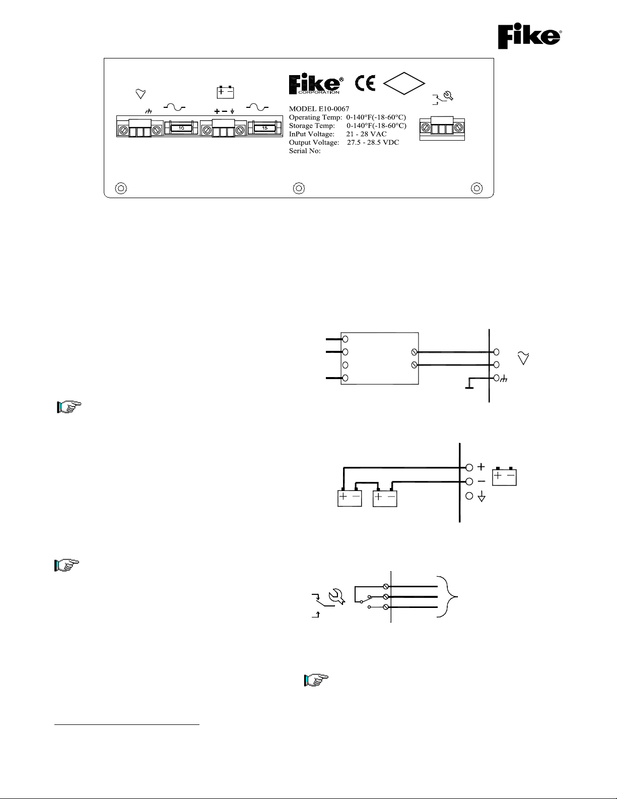
Exhibit 4-2 PSU Bottom View – P3-P5 Wiring Connections
4.4 INPUTS
4.4.1 AC Power Supply (P3)
The AC supply to the EPACOSystem shall be
connected to a 100V5, 120V or 240V 15A breaker
dedicated for the Fike System. The EPACO
System components have DIN rail mounting for
ease of installation. The transformer for the
system should be mounted within 3 meter (10 feet)
of the PSU using minimum 2.08 mm2(14AWG)
cabling. Should the PSU try to pull more than 15
Amps of power from the 25VAC input, the
adjacent 15 Amp protection fuse would open.
Note: Additional circuit protection on the
primary & secondary of the transformer
shall be in accordance with the Local
Authority Having Jurisdiction (AHJ).
4.4.2 Battery Input (P4)
The battery input to the PSU is intended to be
from 2 each 12VDC lead acid batteries connected
in series (located in a vented enclosure). The
internal charger can charge up to 75 amp-hours of
battery. Should the PSU try to pull more than 15
Amps of power from the batteries, the adjacent 15
Amp protection fuse would open.
Note: When applying power to a system,
always connect the AC input first and then
apply the battery power.
Terminals at batteries must be insulated
for CSA.
4.5 OUTPUTS
4.5.1 Trouble Relay (P5)
The trouble relay is available to provide PSU
status to monitoring equipment. The trouble relay
is a “fail-safe” relay that will transfer upon any
system trouble or supervisory condition. This can
be used for equipment shutdown, visual, audible,
5Not FM Approved for 100 VAC.
or other type annunciation. Trouble conditions
may or may not affect the protection system’s
ability to respond to a deflagration, but must be
acknowledged and identified prior to continuing to
run the process.
Exhibit 4-3 AC Power Input
Exhibit 4-4 Battery Input
Exhibit 4-5 Trouble Relay Output
Note: The relay designations (NO, NC, and C)
are shown in the de-energized state with no
power applied. When the EPC is powered and
the controller is in the NORMAL state, the
trouble relay is energized. (The trouble relay
marking is opposite of what is expected).
N
L
P3
(Ordered Seperately) -
+
Transformer
PSU
25VAC
Protective
Earth
PSU
24VDC
P4
12VDC
12VDC
No
Connection
Process Monitoring
NO
P5
C
NC
Equipment (*See Note*)
P3
25VAC
L N
15A
P4
24VDC
P5
NO NC C
FM
APPROVED
Contact: www.fike.com
15A
FM 3020541 Power Supply Unit Installation & Operation Instructions Page 7 of 21
P/N E06-052 Rev. 9 07/08
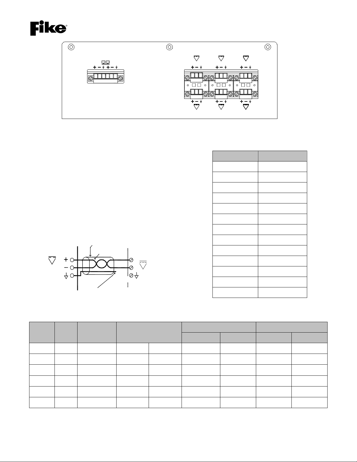
Exhibit 4-6 PSU Top View – P1-P2 Wiring Connections
4.5.2 24VDC Outputs Wiring Size (P2)
The power supply circuit from the PSU to each
EPACOSystem component shall be minimum 0.8
mm2(18AWG). The load of the device(s) connected to
the circuit shall be considered when determing the
wiring limitations and sizing of the 24VDC output (P2).
Maximum circuit wiring resistance (R-line) should
never exceed the values shown in Exhibit 4-8. This
can be calculated using information from National
Electrical Code, NFPA 70. (Exhibit 4-9) or
Max R-line(Ω) = ((Batt name Plate Rating Vdc * 0.85
battery derating) – 18V shutdown) / Load(Amps)
Exhibit 4-7 24VDC Outputs
Load (Amps) Max R-line (Ω)
0.0
0.1 24.0
0.2 12.0
0.3 8.0
0.4 6.0
0.5 4.8
0.6 4.0
0.7 3.4
0.8 3.0
0.9 2.7
1.0 2.4
1.1 2.2
1.2 2.0
Exhibit 4-8 Maximum Circuit Resistance
AWG mm2Stranding Nominal Diameter Uncoated Copper Coated Copper
(Ω/K Ft) (Ω/K m) (Ω/K Ft) (Ω/K m)
18 0.64 Solid 0.040"1.02mm 7.77 25.5 8.08 26.5
18 1.29 7 0.046"1.17mm 7.95 26.1 8.45 27.7
16 1.29 Solid 0.051"1.30mm 4.89 16.0 5.08 16.7
16 1.94 7 0.058"1.46mm 4.99 16.4 5.29 17.3
14 1.94 Solid 0.064"1.63mm 3.07 10.1 3.19 10.5
14 2.58 7 0.073"1.85mm 3.14 10.3 3.26 10.7
Exhibit 4-9 Conductor Properties
P1
BA
EPC-4
P2
EPC-2
24VDC 24VDC
AM
24VDC
EPC-3EPC-1
24VDC 24VDC 24VDC
RC8
24VDC
-
+
Shield
Twisted Pair
No
Connection
P2
24VDC
of Drain Wire
No termination [ insulate ]
EPC, AM or RC8
PSU

Page 8 of 20 Power Supply Unit Installation & Operation Instructions FM 3020541
07/08 P/N E06-052 Rev. 9
4.5.3 Status Bus Connection (P1)
The Status Bus is a low speed communication bus
that transmits control information between the
EPC, Power Supply, Annunciator Module and
Relay Modules. Belden 9841 or RE-Y2Y cabling
is recommended for this circuit. Maximum
resistance R=50 Ω, inductance L=100uH, and
capacitance C=0.02uF with a maximum length of
300m (1000 ft).
Note: The B+ connects to the A+ on the next
device; similarly the B– connects to the A– of
the next device. Install the 140 Ω, 1/2 watt
resistor at each end as shown.
Note: The drain wire should only be connected
on one end of each wire run. Make sure that
the drain wire, which is not connected to a
terminal, is cut and insulated from making
contact to metal or other wiring connections.
Exhibit 4-10 Status Bus Wiring
Additional RC8
Twisted Pair
Shield Wire
-
+-+
Relay Module
B
A
(RC8) #1
P1 Shield
-
+-+
B
A
RC8 #2
P1
-
+-+
Last RC8(Up to 4)
B
A
P1
of Drain Wire [ insulate ]
-
+-+
-
+ + -
Twisted Pair
Shield Wire
Controller (EPC) #1
Explosion Protection
-+ +
-
B
A
P1 Shield
Annunciator
Module (AM)
B
A
+
+
--
B
A
P1
EPC #2 Last EPC (Up to 4)
B
-+-
P1
A
+
Additional EPC
Unit (PSU)
Power Supply
B
A
No termination
Shield Wire
Twisted Pair
P2 Shield P1
140 ohm
140 ohm

FM 3020541 Power Supply Unit Installation & Operation Instructions Page 9 of 21
P/N E06-052 Rev. 9 07/08
Exhibit 5-1 Status LEDs
5.0 OPERATION
5.1 STARTUP
Upon startup, the AC power is measured for a normal
level. If the AC power is too high or too low, the PSU is
held until a normal level is reached. The AC LED is
updated accordingly. Once normal AC power is
verified, the output voltage is measured. Output
voltage must be within normal boundaries to enable
the PSU to continue.
The PSU then detects if batteries are connected with
an appropriate voltage level for battery backup
operation. When the battery level is found normal or
low, the battery charging circuit is enabled. In cases
where the back-up battery voltage exceeds 29.5VDC,
the charging circuit is switched off and the battery will
not be switched in line with the output power.
The five switch-able output circuits are measured
(while in the OFF state) through a supervision circuit to
determine the load connected to the lines. In case the
load is too high, the corresponding output is left
disabled. If the load is found to be appropriate, the
output circuit is switched ON to power up the
connected devices. The output lines are routinely
measured for high loads or excessive voltages. The
normal output voltage must be between 18VDC and
30VDC.
The complete startup sequence typically is completed
within 10 seconds; otherwise a problem has occurred
and should be resolved prior restarting the PSU.
5.2 NORMAL OPERATION
After the startup sequence, normal operation is
entered. During this operation, the AC and DC
power LED’s are both Green; the output voltage
and trouble LED’s are OFF. This operation can
only be stopped in case of total shutdown of the
PSU or when a PC is connected and PC mode
becomes active. In this mode of operation, AC
power, output voltage, charge power, output lines
and battery are continuously measured. Upon
meeting these systems’ parameters, the LED’s are
updated and history is created. When the
parameters are not met, the trouble relay de-
energizes and the trouble LED is lit.
5.3 AC POWER
When the AC supply voltage is within the
prescribed tolerances (1006/120/240VAC -
15/+10%), the AC LED is green. In case of AC
power outage, the PSU enters the battery backup
mode of operation, the AC LED turns off, and the
Trouble LED turns on. If the AC voltage is too low,
the AC LED is red and the Trouble LED will turn
on. If the AC power is too high, outputs are turned
off to prevent exceeding output voltage at the
terminals, the AC LED will blink red, and the
Trouble LED will turn on. The PSU will not power
up on battery power alone. The cooling fan is
monitored in the normal AC operational mode. A
blinking trouble LED indicates fan failure.
6Not FM Approved for 100 VAC.
24VDC
25VAC VOLTAGE
DB9
EPC-1 EPC-2 EPC-4EPC-3 RC8 AM
2A 2A 2A2A 2A 2A
VOLTAGE
25VAC
24VDC
OUTPUT
OUTPUT

Page 10 of 20 Power Supply Unit Installation & Operation Instructions FM 3020541
07/08 P/N E06-052 Rev. 9
Exhibit 5-2 Output Lines
5.4 OUTPUT POWER
The output voltage LED indicates a normal or low
voltage status. When output power exceeds
29.5VDC, the Output Voltage LED turns red, the
PSU disables all outputs except the AM supply
circuit. The history makes a record, and the
trouble relay is activated.
5.5 BATTERY POWER
If the battery is not yet switched in line as result of
the startup or previous scanning, the battery is
again tested for connection and proper operation.
The battery is measured every 10 seconds and is
charged continuously. If battery voltage becomes
too high (29.5VDC) or too low (18VDC), the
battery is switched off, no longer providing backup.
During battery backup mode of operation (due to
AC power loss), the battery is scanned every 50
milliseconds. If the battery power becomes too
low in backup mode (17VDC), the outputs will be
turned off. When the battery drops even lower
because of the load of the AM, the battery will be
switched off causing all output power to be
removed, protecting the battery from deep
discharges. When the shutdown mode is
executed, only complete power off and AC power
restore can restart the PSU.
5.6 OUTPUT LINES (1-5)
Output lines 1-5 are switched ON and OFF
corresponding to the requested status from the
annunciator module (AM). The output lines are
continuously measured for high loads and high
voltage, switching off in case of failure. In case the
fuse is blown, a trouble is generated until a healthy
fuse is inserted. When no Status Bus is present,
all outputs are switched on by default. The green
LED’s are illuminated when the corresponding
output terminal is active. Each output is fuse
protected with a 2A fuse.
5.7 STATUS BUS COMMUNICATION
The PSU is a slave of the Status Bus. The
annunciator module (AM) is the master and polls
the PSU for status information. The AM sends
commands to the PSU to switch outputs on and off
based on user input, typically for system service or
other maintenance activity.
DB9
EPC-1 EPC-2
24VDC
25VAC
EPC-4
EPC-3 RC8
VOLTAGE
AM
2A 2A 2A
2A 2A 2A
OUTPUT LINES 1-6
2 AMP CIRCUIT PROTECTION FUSE
STATUS LED
OUTPUT

FM 3020541 Power Supply Unit Installation & Operation Instructions Page 11 of 21
P/N E06-052 Rev. 9 07/08
5.8 HISTORY
The PSU can store up to 48 history records in a First
in First out (FIFO) table. A time stamp is created with
each event recorded. The time information is updated
each second and will be relative between consequent
events.
The following codes are retrieved through
EPWorksSoftware.
01 AC Power High 14 Output voltage normal 27 Output 1 line fail
02 AC Power Low 15 Outputs user disabled 28 Output 2 line fail
03 No AC Power 16 Outputs user enabled 29 Output 3 line fail
04 AC Power Normal 17 Output 1 on 30 Output 4 line fail
05 Battery High 18 Output 2 on 31 Output 5 line fail
06 Battery Normal 19 Output 3 on 32 PC connected
07 Battery Low 20 Output 4 on 33 Power up
08 Battery Shutdown 21 Output 5 on 34 Status Bus timeout
09 No battery connected 22 Output 1 off 35 Status Bus connect
10 Charge power normal 23 Output 2 off 36 Battery Off
11 Charge power fault 24 Output 3 off 37 Fan Trouble
12 Output voltage high 25 Output 4 off 38 Event List Cleared by EPWorks™
13 Output voltage low 26 Output 5 off 39 Ground Fault
Exhibit 5-3 History Codes

Page 12 of 20 Power Supply Unit Installation & Operation Instructions FM 3020541
07/08 P/N E06-052 Rev. 9
6.0 PERIODIC MAINTENANCE
CAUTION: If assistance is needed before performing any maintenance or service work on the Fike Explosion
Protection equipment and/or systems, contact Fike for instructions.
See Section 11.0 Repair and Return Authorization for contact information.
6.1 GENERAL
Routine system inspections shall be conducted in
accordance with the requirements of the
appropriate local authority having jurisdiction and
National Fire Protection Association Standard
Number 69, Explosion Prevention System, current
edition.
The inspection schedule and procedure set forth
below are provided as a minimum requirement for
Fike Explosion Protection System Controllers,
which operate in moderate environments. These
control panel instructions are to be implemented in
conjunction with complete system inspection
instructions.
During initial system checkout or start-up, the Fike
Factory Field Personnel, due to process
operational characteristics and/or historical
inspection data on the specific process, may
determine that an additional inspection is required.
If this occurs, it will be in addition to the following
maintenance schedule.
It is extremely important to closely monitor the
operational characteristics of your system during
the first few days and weeks after the initial start-
up.
6.2 INSPECTION PROCEDURE
The following is the recommended procedure to
follow when conducting an inspection.
Step 1: Disable the Control Panel
Step 2: Shunt the GCA’s and install jumpers
Step 3: Re-Arm the Control Panel and Disable
Step 4: Calibrate the pressure detectors
Step 5: Cycle the Explosion Isolation Valves – if
present
Step 6: Checkout the panel
Step 7: Reconnect the GCA’s and log the
container pressures and serial numbers
Step 8: Re-arm the system
6.3 ROUTINE INSPECTIONS
These inspections are to be performed by Fike
Field Personnel or personnel trained and certified
by Fike.
To perform an inspection, it is important to first
obtain all pertinent data that relates to the specific
system being inspected. The required information
includes:
System Engineered Drawings
Component Location Drawing No._________
Field Wiring Drawing No.____________
Copy of Manuals, Specifications or
Documents Referenced on Fike System
Engineered Drawings
Inspection Equipment
Operating Specifications on Each Component
being inspected.
6.4 THREE-YEAR REPLACEMENT
Replace all system batteries.
6.5 TEN-YEAR REPLACEMENT
Replace all GCA actuators, following all safe
handling practices and recommendations.
Note: The ten-year replacement is based
upon a -30°F to 140°F (-34°C to 60°C)
actuator temperature. The replacement
frequency may be more frequent when
exposure to higher temperature or harsh
environments is experienced.

FM 3020541 Power Supply Unit Installation & Operation Instructions Page 13 of 21
P/N E06-052 Rev. 9 07/08
7.0 DECOMMISSIONING PROCEDURE / CHECK-LIST
The following procedure must only be performed by a Fike qualified Service Engineer, who has been assigned to
prepare and complete the decommissioning of the above referenced Explosion Protection System.
Each step in the listed procedure must be adhered to and completion/acceptance of this form is mandatory. The
Service Engineer must check off each of the following steps. In the case of non-compliance, the observed
discrepancy must be corrected before completion of the system decommissioning.
Exhibit 7-1 Decommissioning Steps
Steps / Description
1. Use Fike system/project component location
diagram to record and verify the locations of all
Fike system components for each zone and
system.
pass fail Remark/
Note No.
2. Control Panel to be disarmed/shutdown. pass fail Remark/
Note No.
3. All suppressor/valve actuators to be shunted. pass fail Remark/
Note No.
4. Each suppressor/valve container to be
depressurised.
Warning:Do not ventilate nitrogen in a
confined space.
pass fail Remark/
Note No.
5. Power supply to the control panel to be Isolated
by the customer and disconnected to prevent
accidental reconnection. Fike to verify.
pass fail Remark/
Note No.
6. Control panel battery to be disconnected and
removed for disposal.
pass fail Remark/
Note No.
7. Each actuator is to be removed and placed in a
storage housing, to be either stored on site or
removed for disposal.
pass fail Remark/
Note No.
8. Verify that all suppressor/valve gauges are
reading zero, replace fill valve cap loosely.
pass fail Remark/
Note No.
ATTENTION: SYSTEM IS NOW DECOMMISSIONED AND READY FOR
DISMOUNTING BY THE CUSTOMER.

Page 14 of 20 Power Supply Unit Installation & Operation Instructions FM 3020541
07/08 P/N E06-052 Rev. 9
8.0 SPARE PARTS
Part Number Description
E10-0067 Power Supply Unit (PSU)
02-10644 Transformer 120/240V
02-10879 Transformer 100V
02-4174 Fuse, 15A mini automotive blade type (Both AC and Battery fuse)
02-4181 Fuse, 2A mini automotive blade type (DC output fuse)
02-10415 Six (6) Position Wire Terminal Block (P1)
02-10417 Three (3) Position Wire Terminal Block (outputs) (P2 & P5)
02-10753 Three (3) Position Wire Terminal Block AC (inputs) (P3)
02-10753 Three (3) Position Wire Terminal Block Battery (inputs) (P4)
02-10876 End of Line Resistor, 140 Ohm, 0.5 Watt for Status Bus (P1)
Exhibit 8-1 PSU Spare Parts List
Table of contents
Other Fike Power Supply manuals

Popular Power Supply manuals by other brands


Stromtank
Stromtank S 2500 owner's manual

EVGA
EVGA T2 Series user manual

Electro-Harmonix
Electro-Harmonix S8 manual

Monster Power
Monster Power Power GreenPower HDP 900G PowerCenter Instructions and warranty information

Radio Shack
Radio Shack Regulated Power Supply owner's manual

Delta Electronics
Delta Electronics L36SA datasheet


