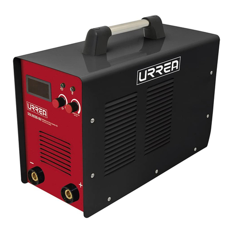
Urrea SURTEK SOLI5 140-110 Dimensions and installation guide

SOLI5140-110
Soldadora de Arco Inverter de CD
DC Inverter Arc Welder
ATENCIÓN: Lea, entienda y siga las instrucciones de seguridad contenidas en este
manual, antes de operar esta herramienta.
WARNING: Read, understand and follow the safety rules in this manual, before operating this tool.
Manual de Usuario y Garantía.
User’s Manual and Warranty.
SOLI5140-110 manual.indd 1 17/11/15 2:37 p.m.

2
ENGLISHESPAÑOL
General safety rules
Electric safety
Personal safety
Tool use and care
Preparations
Specific safety rules for
DC Arc welders
Features
Installation instructions
Operation instructions
Maintenance
Technical data
Troubleshooting
Warranty policy
Normas generales de seguridad
Seguridad eléctrica
Seguridad personal
Utilización y cuidados de las
herramientas eléctricas
Preparaciones para instalación
Advertencias de seguridad para
Soldadoras inverter
Características
Instrucciones de instalación
Instrucciones de operación
Mantenimiento y servicio
Especificaciones técnicas
Solucionador de problemas
Garantía
10
10
11
11
12
12
12
13
13
14
14
15
16
3
3
4
5
5
6
6
6
7
8
8
9
16
CONTENIDO CONTENT
SÍMBOLOS SYMBOLS
PELIGRO, ADVERTENCIA, PRECAUCIÓN:
Indica un riesgo personal o la posibilidad
de un daño.
DANGER, CAUTION, WARNING: Indicates risk of
personal injury and/or the possibility of damage.
SOLI5140-110 manual.indd 2 17/11/15 2:37 p.m.

3
ESPAÑOL•Manual de Usuario
NORMAS GENERALES DE SEGURIDAD
Esta SOLDADORA INVERTER tiene caracterís-
ticas que harán su trabajo más rápido y fácil.
Seguridad, comodidad y confiabilidad fueron
previstos como prioridad para el diseño del
mismo, haciendo más fácil su operación.
ADVERTENCIA: Lea todas las advertencias
de seguridad y todas las instrucciones. La omi-
sión de alguna de las advertencias e instruccio-
nes que se enlistan a continuación puede dar
como resultado un choque eléctrico, fuego y/o
un daños serios.
CONSERVE TODAS LAS ADVERTENCIAS Y
TODAS LAS INSTRUCCIONES.
SEGURIDAD EN EL ÁREA DE TRABAJO
Mantenga el área de trabajo limpia y bien ilu-
minada. Las áreas desordenadas y oscuras pro-
vocan accidentes.
No maneje herramientas eléctricas en atmós-
feras explosivas, tales como en presencia de
líquidos inflamables, gases o polvo. Las herra-
mientas eléctricas crean chispas que pueden
encender el polvo o los humos.
Mantenga alejados a los niños y curiosos
mientras maneja una herramienta eléctrica.
Las distracciones pueden causarle la pérdida
del control.
La soldadora por arco con polaridad inversa
SURTEK está diseñada para ser utilizada con
el sistema avanzado MOSFET y diodo de recu-
peración rápida como su control principal; así
mismo cuenta con componentes de transferen-
cia y está asistida por un sistema de circuito de
control especialmente desarrollado.
Posee corriente para soldadura regulada uni-
formemente lo que permite que la fuente de
energía de la soldadora se adapte a excelen-
tes procedimientos de soldadura. Se ha mejo-
rado la capacidad de protección del soldador
para garantizar el uso del equipo sin riesgos.
Es muy utilizado para soldaduras de materiales
como el acero de bajo carbono, acero inoxida-
ble, acero de alta resistencia, acero de aleación
y hierro fundido.
Características principales de la soldadora de
arco de polaridad inversa:
a) Se destaca por su tamaño reducido y su poco
peso. Es muy utilizado para trabajos de tapi-
cería, reparaciones y para trabajos a cambio
abierto.
b) Excelente manejo del arco y transición de
derretimiento y goteo.
c) Gran protección durante el funcionamiento.
Protege la soldadora de sobrecalentamientos,
picos de alto y bajo voltaje, sobre-corriente,
entre otros. Cuando la compensación del su-
ministro principal de energía no es menor a
±15%, éste puede aumentar mientras que la
corriente de la soldadora se reduce. Gracias a
su función de anti-bloqueo, el sistema de con-
trol puede responder a la fuente de energía, a
la pieza de trabajo, al electrodo y a cambios de
funcionamiento a una rapidez menor a 1 m/s
para estabilizar la salida de corriente.
d) Fácil de conectar. Para realizar la conexión
externa, esta inverter utiliza todos los adap-
tadores, lo que permite realizar una conexión
rápida y segura con un funcionamiento simple
y confiable.
SEGURIDAD ELÉCTRICA
La clavija de la herramienta eléctrica debe
coincidir con receptáculo. No modificar nunca
la clavija de ninguna manera. No usar ningún
adaptador de clavijas con herramientas eléctri-
cas puestas a tierra. Clavijas no modificadas y
bases coincidentes reducirán el riesgo de cho-
que eléctrico.
Evite el contacto del cuerpo con superficies
puestas a tierra como tuberías, radiadores, co-
cinas eléctricas y refrigeradores. Hay un riesgo
aumentado de choque eléctrico si su cuerpo
está puesto a tierra.
No exponga las herramientas eléctricas a la llu-
via o a condiciones de humedad. El agua que
entre en la herramienta aumentará el riesgo
de choque eléctrico.
No abuse del cable. No usar nunca el cable para
llevar, levantar o desenchufar la herramienta
eléctrica. Mantenga el cable lejos del calor,
aceite, cantos vivos o piezas en movimiento.
Los cables dañados o enredados aumentan el
riesgo de choque eléctrico.
Cuando maneje una herramienta eléctrica en
el exterior, use una prolongación de cable ade-
cuada para uso en el exterior. El uso de una
prolongación de cable adecuada para uso en el
exterior reduce el riesgo de choque eléctrico.
SOLI5140-110 manual.indd 3 17/11/15 2:37 p.m.
4
“ESTA HERRAMIENTA CUENTA CON UN
SUJETACABLE TIPO “X“, EN CASO DE DAÑAR-
SE EL CORDÓN DE ALIMENTACIÓN, ÉSTE DE-
BERÁ SER REEMPLAZADO POR EL FABRICANTE,
SUS CENTROS DE SERVICIO AUTORIZADOS, O
PERSONAL CALIFICADO A FIN DE EVITAR RIES-
GOS.”
EXTENSIONES DE CABLE
NOTA: El uso de cables dañados incrementa el
riesgo de descargas eléctricas o quemaduras.
Si es necesario un cable de extensión, debe ser
usado un cable con el tamaño adecuado de los
conductores. La tabla de la siguiente página,
muestra el tamaño correcto para usar depen-
diendo en la longitud del cable y el rango de
amperaje especificado en la etiqueta de valo-
res nominales del producto. Si está en duda,
use el rango próximo más grande.
Siempre use cables de extensión listados en UL,
CSA ó NOM.
TAMAÑOS RECOMENDADOS DE EXTENSIONES
DE CABLE:
Cuando esté usando el producto afuera, use
una extensión para exteriores marcadas con lo
siguiente: “WA” o “W”. Estas extensiones están
pensadas para trabajar en exteriores y reducen
el riesgo de descarga eléctrica.
SEGURIDAD PERSONAL
Esté alerta, vigile lo que está haciendo y use el
sentido común cuando maneje una herramien-
ta eléctrica. No use una herramienta eléctrica
cuando esté cansado o bajo la influencia de
drogas, alcohol o medicamentos. Un momento
de distracción mientras maneja herramientas
eléctricas puede causar un daño personal serio.
Use equipo de seguridad. Lleve siempre pro-
tección para los ojos. La utilización para las
condiciones apropiadas de un equipo de segu-
ridad tal como mascarilla anti-polvo, zapatos
no resbaladizos, gorro duro, o protección para
los oídos reducirá los daños personales.
Evite un arranque accidental. Asegúrese de
que el interruptor está en posición apagado
antes de conectar a la red y/o a la batería, co-
ger o transportar la herramienta. Transportar
herramientas eléctricas con el dedo sobre el
interruptor o enchufar herramientas eléctricas
que tienen en interruptor en posición encendi-
do invita a accidentes.
Retire llaves o herramienta antes de arrancar
la herramienta eléctrica. Una llave o herra-
mienta dejada unida a una pieza rotativa de
una herramienta eléctrica puede causar un
daño personal.
No se sobrepase. Mantenga los pies bien asen-
tados sobre el suelo y conserve el equilibrio en
todo momento. Esto permite un mejor control
de la herramienta eléctrica en situaciones in-
esperadas.
Vista adecuadamente. No vista ropa suelta o
joyas. Mantenga su pelo, su ropa y guantes
alejados de las piezas en movimiento. La ropa
suelta, las joyas o el pelo largo pueden ser co-
gidos en las piezas en movimiento.
Si hay dispositivos para la conexión de medios
de extracción y recolección de polvo, asegúre-
se de que éstos estén conectados y se usen co-
rrectamente. El uso de estos dispositivos puede
reducir los peligros relacionados con el polvo.
IMPORTANTE: Este aparato no se destina
para utilizarse por personas (incluyendo niños)
cuyas capacidades físicas, sensoriales o menta-
les sean diferentes o estén reducidas, o carez-
can de experiencia o conocimiento, a menos
que dichas personas reciban una supervisión o
capacitación para el funcionamiento del apa-
rato por una persona responsable de su segu-
ridad. Los niños deben supervisarse para ase-
gurar que ellos no empleen los aparatos como
juguete.
• SIEMPRE respete las reglas de seguridad e hi-
giene. Use ropa protectora para evitar lesiones
en los ojos y la piel.
• Use la máscara para proteger la cabeza mien-
tras utiliza la soldadora. Visualice su trabajo
solamente a través de la lente con filtro.
• Bajo ninguna circumstancia permita que al-
guna parte de su cuerpo esté en contacto con
las salidas bipolares de la soldadora (la manija
del soporte del electrodo y la pieza de trabajo).
SOLI5140-110 manual.indd 4 17/11/15 2:37 p.m.

5
ESPAÑOL•Manual de Usuario
UTILIZACIÓN Y CUIDADOS DE LAS
HERRAMIENTAS ELÉCTRICAS
No fuerce la herramienta eléctrica. Use la he-
rramienta eléctrica correcta para su aplicación.
La herramienta eléctrica correcta hará el tra-
bajo mejor y más seguro al ritmo para la que
fue concebida.
No use la herramienta eléctrica si el interrup-
tor no gira “encendido” y “apagado”. Cual-
quier herramienta eléctrica que no pueda con-
trolarse con el interruptor es peligrosa y debe
repararse.
Desenchufe la clavija de la fuente de alimen-
tación y/o de la batería antes de efectuar
cualquier ajuste, cambio de accesorios, o de
almacenar las herramientas eléctricas. Tales
medidas preventivas de seguridad reducen el
riesgo de arrancar la herramienta accidental-
mente.
Almacene las herramientas eléctricas inactivas
fuera del alcance de los niños y no permita el
manejo de la herramienta eléctrica a personas
no familiarizadas con las herramientas o con
estas instrucciones. Las herramientas eléctricas
son peligrosas en manos de usuarios no entre-
nados.
Mantenga las herramientas eléctricas. Com-
pruebe que las partes móviles no estén des-
alineadas o trabadas, que no haya piezas ro-
tas u otras condiciones que puedan afectar la
operación de las herramientas eléctricas. Las
herramientas eléctricas se reparan antes de su
uso, cuando están dañadas. Muchos acciden-
tes son causados por herramientas eléctricas
pobremente mantenidas.
Mantenga las herramientas de corte afiladas y
limpias. Las herramientas de corte mantenidas
correctamente con los bordes de corte afilados
son menos probables de trabarse y más fáciles
de controlar.
Use la herramienta eléctrica, accesorios y pun-
tas de herramienta, etc. de acuerdo con estas
instrucciones y de la manera prevista para el
tipo particular de herramienta eléctrica, te-
niendo en cuenta las condiciones de trabajo
y el trabajo a desarrollar. El uso de la herra-
mienta eléctrica para aplicaciones diferentes
de las previstas podría causar una situación de
peligro.
SERVICIO
Haga revisar su herramienta eléctrica por un
servicio de reparación calificado usando sola-
mente piezas de reemplazo idénticas. Esto ga-
rantizará que la seguridad de la herramienta
eléctrica se mantiene.
PREPARACIONES DE INSTALACIÓN
• Se deben tomar precauciones para proteger
al operador y al equipo de la caída de objetos.
• El polvillo, el ácido y los suciedad corrosiva del
ambiente en el área de trabajo no deben exce-
der el límite permitido por la norma (quedan
excluidas las emanaciones de la soldadora).
• La soldadora debe ser instalada dónde no
quede expuesta al sol y a la lluvia. También,
debe ser almacenada en lugares sin humedad y
a una temperatura entre -10°~40°C.
• La soldadora debe tener un espacio de 50cm
a su alrrededor para una buena ventilación.
• Asegúrese que no haya elementos de metal
extraños que puedan estar en contacto con el
equipo.
• No debe haber vibraciones violentas en el
área de rodea la soldadora.
• Asegúrese de que no haya interferencias en
el área de instalación de la soldadora.
• Asegúrese de que haya suficiente abasteci-
miento de energía para que la soldadora tra-
baje correctamente. Cualquier fuente de ener-
gía para la soldadora debe ser instalada con
equipos de protección.
• La soldadora debe ser instalada sobre una su-
perficie horizontal. Si existe un desnivel mayor
a 15° se debe colocar algún equipo anti vuelco.
ADVERTENCIAS DE SEGURIDAD
PARA SOLDADORAS INVERTER
• La soldadora de arco inverter es un producto
eléctrico cuyos componentes son muy deli-
cados. No cambie ni ajuste nada precipitada-
mente porque puede dañarse el interruptor.
• Corrobore que la instalación sea correcta:
que la conexión a tierra sea confiable, etc.
• El humo y los gases emitidos al soldar son no-
civos para la salud. Asegúrese de trabajar en
lugares ventilados o con extractores para evitar
la inhalación de humo y otras emanaciones.
SOLI5140-110 manual.indd 5 17/11/15 2:37 p.m.

6
• Por favor recuerde mantener a las perso-
nas alejadas de los rayos del arco mientras se
suelda. Esto se debe a la interferencia de los
rayos del arco.
• No permita que nadie aparte del operador
desmonte o realice modificaciones en la solda-
dora.
• No permita que personas con marcapasos o
cualquier otro elemento susceptible a electro-
magnetismo se acerquen a la soldadora ya que
puede interferir con el normal funcionamiento
de éste.
• La soldadora no debe ser usada para el des-
hielo de tuberías.
• Está prohibida la sobrecarga. Por favor con-
trole el factor de carga continua.
• Asegúrese que la soldadora tenga una cone-
xión a tierra confiable.
• Asegúrese que no haya cortocircuito en am-
bas salidas de la soldadora.
• Asegúrese de que siempre haya suficiente
cable para las conexiones de entrada y salida,
y evite la exposición en el exterior. Personal
calificado debe controlar regularmente la ins-
talación de la soldadora cada seis meses lo que
implica:
· Realizar una limpieza rutinaria para asegu-
rarse que no existan anormalidades como
conexiones sueltas en la soldadora.
· Las partes externas instaladas a la soldadora
deben garantizar el buen funcionamiento de
ésta.
· Controle el cable de la soldadora para verifi-
car si puede ser seguir siendo utilizado antes
de que se gaste.
· Remplace inmediatamente el cable de en-
trada de la soldadora si lo encuentra pelado
o dañado.
CARACTERÍSTICAS
ESTRUCTURA DE LA SOLDADORA
Este tipo de soldadoras, utilizan estructuras
móviles; en la parte frontal superior se encuen-
tra el interruptor de encendido (1), la perilla
de regulación de corriente de la soldadora (2),
una luz piloto verde de encendido(3), una luz
piloto roja que indica algún tipo de anorma-
lidad (4), una pantalla de lectura e indicación
de voltaje (5). En la parte inferior se encuen-
tran los conectores rápidos de salida de co-
rriente “+” y “-“ (6). En la parte posterior se
encuentra el ventilador de enfriamiento, el
cable principal de la fuente de energía. En la
parte superior hay una manija para el traslado
del equipo. Al abrir la cubierta se encuentra un
transformador principal y tarjeta impresa de
control. En la parte inferior se encuentra el re-
actor de salida, el transformador principal, etc.
En el centro se encuentra instalado un radiador
con elementos eléctricos.
INSTALACIÓN
Conectar el cable de alimentación ubicado
en el panel trasero de la soldadora al circuito
eléctrico monofásico de 127 V con interruptor.
Fuentes de alimentación eléctricas de más de
127 V están estrictamente prohibidas ya que
pueden dañar severamente la soldadora. Si
esta conexión es realizada por el usuario, este
será responsable de los daños causados.
ATENCIÓN: la conexión a tierra del cableado
de energía no es una conexión de energía cero.
2
4
6
5
3
1
Cable de
alimentación
monofásica.
Toma a tierra.
Porta-electrodo.
Pieza de
trabajo. Soporte
de fijación. Cable
a tierra.
SOLI5140-110 manual.indd 6 17/11/15 2:37 p.m.

7
ESPAÑOL•Manual de Usuario
Conexión de la soldadora al porta electrodo
Conectar el cable del porta electrodo de sol-
dadura en el polo “+” de la toma rápida de
corriente que se encuentra en la parte inferior
del panel frontal, luego girar en sentido de las
agujas del reloj hasta que esté ajustada.
Conexión de la soldadora a la pieza de trabajo
Conectar el cable del la grampa a tierra con
la conexión rápida de corriente de salida “-“
que se encuentra en la parte inferior del pa-
nel frontal, luego girar en sentido de la agujas
del reloj hasta que esté ajustada. Conectar la
grampa a la pieza de soldar.
ATENCIÓN: No utilice planchas de acero o
materiales similares ya que son malos conduc-
tores para conectar la soldadora y la pieza de
trabajo.
INSTRUCCIONES DE OPERACIÓN
ATENCIÓN: La categoría de protección de la
soldadora por arco de polaridad inversa es de
IP21S. Está prohibido insertar en la soldadora
el dedo o una varilla redonda de diámetro in-
ferior a 12,5 mm (especialmente si es de metal).
No se debe ejercer fuerza sobre la soldadora.
• La luz piloto de protección se encenderá des-
pués de un largo período de uso de la soladora.
Esto indica que la temperatura interna es supe-
rior a la permitida por lo que el equipo debe
ser apagado hasta que se enfríe.
Se puede continuar utilizando después de que
la luz piloto de protección se apague.
• Se debe apagar la alimentación de energía
al finalizar o si se abandona temporalmente el
lugar de trabajo temporalmente.
• El operador deber usar ropa de trabajo de
lona y máscara de soldar para prevenir acciden-
tes por el arco o por la radiación térmica.
• Se deben colocar pantallas protectoras alre-
dedor del área de trabajo para prevenir que el
arco lastime a otras personas.
• No debe haber materiales inflamables o ex-
plosivos en los alrededores del área de trabajo.
• Todas las conexiones del equipo deben estar
correctas y seguras.
PROCEDIMIENTO BÁSICO DE OPERACIÓN
a) Active el interruptor principal, se encenderá
la luz piloto de encendido.
b) Regule el potenciómetro de corriente de la
soldadora al valor deseado.
c) Tome el porta electrodo y apúntelo hacia la
zona a soldar y haga contacto con el electrodo,
inmediatamente se producirá el arco eléctrico
y la luz piloto de equipo soldando se encen-
derá.
REEMPLAZO DEL ELECTRODO
Cuando sólo quede de 1 a 2 cm de electrodo es
necesario cambiarlo por uno nuevo para poder
continuar con el trabajo de soldadura.
ATENCIÓN: La fusión del electrodo se realiza
a altas temperaturas, en el recambio no haga
contacto directo con la mano. El electrodo re-
cambiado debe colocarse en una caja metálica.
El porta electrodo no debe morder el revesti-
miento del electrodo.
Para iniciar el arco eléctrico el electrodo debe
rasparse ligeramente en la pieza a soldar, de lo
contrario puede pegarse en la varilla.
LIMPIEZA DE ESCORIA
Al finalizar el trabajo de soldadura, por favor
utilice un martillo especial quita escoria para
remover la escoria de la superficie del riel de
la soldadora.
ATENCIÓN: La limpieza de la escoria se debe
realizar una vez que ésta se haya enfriado y
endurecido.
No se debe apuntar a otras personas cuando se
remueve la escoria para evitar herir a terceros.
MANTENIMIENTO Y SERVICIO
A diferencia de las soldadoras convenciona-
les, la soldadora de polaridad inversa es un
producto científicamente sofisticado que uti-
liza modernos elementos electrónicos de tec-
nología avanzada por lo que se requiere de
personal especializado para realizar su man-
tenimiento. Sin embargo, debido a que posee
poco elementos que se desgasten fácilmente,
no necesita mantenimiento periódico además
de la limpieza de rutina. Sólo personal califi-
Conector rápido del
cable de conexión
de la soldadora.
Conexión a la
pieza de trabajo.
SOLI5140-110 manual.indd 7 17/11/15 2:37 p.m.

8
cado está autorizado a realizar tareas de repa-
ración. Es recomendable que los clientes con-
tacten nuestra empresa para obtener soporte
o servicio técnico cuando se encuentren con
problemas técnicos que no puedan solucionar
TAREAS DE MANTENIMIENTO:
Limpieza de la suciedad. El personal especiali-
zado debe limpiar regularmente el polvillo de
la soldadora con aire comprimido seco (com-
presor o equipo similar). Al mismo tiempo, se
puede revisar para asegurarse que no haya
componentes o partes sueltas en el interior
del equipo. Si hay acumulación de polvillo, la
limpieza se debe realizar de inmediato. Gene-
ralmente, la limpieza se realiza una vez al año
a menos que haya polvillo acumulado en el in-
terior de la soldadora. En este caso, la limpieza
debe realizarse cada cuatro meses.
Mantenimiento del enchufe del cable de la
soladora en buenas condiciones. El enchufe
del cable de la soldadora debe ser revisado
de vez en cuando. Si se utiliza regularmente,
debe revisarse al menos una vez al mes. Sin
embargo, debe controlarse cada vez si está en
movimiento.
ATENCIÓN: Si el nivel principal de voltaje
es mayor al normal, antes de reparar se deben
tomar medidas de seguridad para evitar elec-
trocución accidental. ¡Está prohibido que per-
sonal no calificado abra la cubierta del equipo!
Se debe interrumpir la electricidad antes de
realizar la limpieza del equipo.
Nunca altere los cables o dañe los componen-
tes al realizar la limpieza.
FASES
VOLTAJE DE ENTRADA
FRECUENCIA
EFICIENCIA
RANGO DE CORRIENTE
CORRIENTE AL SOLDAR
CLASE DE PROTECCIÓN
FACTOR DE POTENCIA COS
ɸ
PESO
1 ~
127 V ~
60 Hz
ɳ 80%
(20 - 140) A
140 A (60%)
IP21S
0,8
7 kg (15,4 lb)
…
–
DATOS TÉCNICOS
SOLI5140-110 manual.indd 8 17/11/15 2:37 p.m.

9
PROBLEMAS
1
2
3
4
5
6
7
La luz piloto de seguridad
está encendida.
La perilla de ajuste ubicada
en el panel frontal no fun-
ciona.
El ventilador de enfriamien-
to no funciona o se mueve
lentamente.
No hay carga de voltaje.
El porta electrodo y el cable
se recalientan: las tomas
de los polos “+” y “-“se ca-
lientan.
La oscilación de la fuente de
energía.
Otros
1. Mala ventilación de energía
hacen encender la protección de
sobre calentamiento.
2. La temperatura circunstancial es
muy elevada.
3. El uso excede el tiempo de ciclo
de trabajo.
El potenciómetro está roto (regu-
lador de corriente).
1. Desabastecimiento de la fase
2. El interruptor está roto.
3. El ventilador está roto.
4. El cable está roto o desconec-
tado.
1. La soldadora se está sobre ca-
lentando.
2. El interruptor está roto.
1. La capacidad del porta electro-
do es demasiado pequeña.
2. El cable es pequeño.
3. Hay una resistencia mayor en-
tre el porta electrodo y el cable.
1. Se realiza la carga en períodos
largos (más de dos días)
2. Durante el proceso de solda-
dura.
1. Mejore las condiciones de ventilación.
2. Se recuperará automáticamente cuando la temperatura dismi-
nuya.
3. Se recuperará automáticamente cuando la temperatura dismi-
nuya.
1. Reemplace el potenciómetro.
1. Recupere la fase
2. Reemplace el interruptor.
3. Reemplace o repare el ventilador.
4. Revise la conexión.
1. Vea No 1
2. Reemplace el interruptor.
1. Reemplace el porta electrodo por una de mayor capacidad.
2. Reemplace el cable por otro que cumpla con los requeri-
mientos
3. Remueva la capa de óxido y ajuste.
1. Ho hay falla. La descarga se debe a la capacidad de carga del
filtro de energía. Encienda la fuente de alimentación de energía.
2. Contáctenos.
Por favor, contacte al fabricante/ proveedor.
ANÁLISIS SOLUCIONES
SOLUCIONADOR DE PROBLEMAS
ESPAÑOL•Manual de Usuario
SOLI5140-110 manual.indd 9 17/11/15 2:37 p.m.

10
GENERAL SAFETY RULES
Your DC’s INVERTER has many features that
will make your job faster and easier. Safety,
performance and reliability have been given
top priority in the design of this tool, qualities
to make easy to maintain and to operate.
WARNING: Read and understand all in-
structions. Failure to follow all indications list-
ed below, may result in electric shock, fire and/
or serious personal injury.
SAVE THESE INSTRUCTIONS.
SAFETY IN WORKING AREA
Keep your work area clean and well lit. Clut-
tered benches and dark areas may cause acci-
dents. Do not operate power tools in explosive
atmospheres, such as in the presence of flam-
mable liquids, gases or dust. Some power tools
create sparks which may provoke fire.
Keep away observers, children and visitors
while operating a power tool. Distractions can
cause you to lose control.
This DC Inverter Arc Welder is designed to be
used with the advanced MOSFET and rapid re-
covery diode as its main control and transfer
components and assisted with the specially de-
veloped control circuit, it has uniformly regu-
lated welding current which enable the weld-
ing power source to achieve the adaptability
to the excellent welding procedures. It largely
enhanced the welder’s protection abilities to
ensure safety welding operation. It is quite
popular in welding the materials like low-car-
bon steel, stainless steel, high-intension steel,
alloy steel and cast iron.
The highlighted characteristics of series DC In-
verter Arc Welder:
a) Featured with small volume and light
weight, it widely used in upholstering field,
repairing field and fieldwork.
b) Excellent arc-piloting feature and melt &
drip transition feature.
c) By various sound protection performance, it
can keep the welding machine from overheat-
ing, over voltage, under voltage, over current
and so on. When the main supply compensa-
tion is not less than ±15%, it can increase while
the welding current reduces. Because of its anti
jamming high performance, the control system
can respond to the power source, work piece,
electrode and operational changes with less
than 1 m/s speed in order to keep steady out-
put of the current.
d) Easy connection. To conduct external con-
nection, this inverter use all the connectors,
which can facilitate quick and safe connection
with simple but reliable performance. No noti-
fication will be given if the manual’s content or
welder’s function change.
ELECTRIC SAFETY
Double insulation eliminates the need for the
three wire grounded power cord and ground-
ed power supply system. Avoid the body con-
tact with grounded surfaces such as pipes, ra-
diators and refrigerators. There is an increased
risk of electric shock if your body is grounded.
Don’t expose power tools to rain or wet condi-
tions. The presence of water into power tools
will increase the risk of electric shock.
Do not abuse of the power cord. Never use the
power cord to carry the tool and do not pull
the plug off the outlet. Keep the cable away of
heat, oil, sharp edges or moving parts. Replace
damaged cords immediately. Damaged cords
increase the risk of electric shock.
When operating a power tool outside, use an
outdoor extension cord marked “W-A” or “W”.
These cords are rated for outdoor use and re-
duce the risk of electric shock.
EXTENSION CORDS
Replace damaged cords immediately. The use
of damaged cords can shock, burn or electric
shock. If an extension cord is necessary, a cord
with adequate size conductors should be used
to prevent excessive voltage drop, loss of pow-
er or overheating. The table below shows the
correct size to use, depending on cord length
and nameplate amperage rating of tools. In
case of doubt use the next heavier gauge. Al-
ways use UL listed extension cords.
SIZE RECOMMEND EXTENSION CABLES
SOLI5140-110 manual.indd 10 17/11/15 2:37 p.m.

11
ENGLISH•User's manual
PERSONAL SAFETY
Stay alert, watch what you are doing and use
common sense when operating a power tool.
Don’t use the tool if you are tired or under the
influence of drugs, alcohol or medication. A
moment of inattention while operating power
tools may cause a serious personal injury.
Dress properly. Do not wear loose clothing
or jewelry. Contain long hair. Keep your hair,
clothing and gloves away of moving parts.
Loose clothes, jewelry or long hair can be
caught in moving parts.
Avoid an accidental starting. Be sure that the
switch is OFF before plugging in. Carrying
tools with the finger on the switch or plug in
the tool switch in ON may cause accidents.
Remove the adjusting keys or wrenches be-
fore turning the tool on. A wrench or a key
that is left close to a rotating part of the tool
may provoke a personal injury.
Do not overreach. Keep proper footing and
balance at all times. Proper footing and bal-
ance enables better control of the tools on un-
expected situations. Use safety equipment. Al-
ways wear eye protection. Dust mask, nonskid
safety shoes, hard hat, or hearing protection
must be used for appropriate conditions.
Before connecting the tool to a power source
(receptacle, outlet, etc.) be sure that the volt-
age supplied is the same as that one specified
on the nameplate of the tool. To use a not
specified voltage may cause a serious injury to
the user as well as damage the tool.
IMPORTANT: This appliance is not intended
for use by persons (including children) with re-
duced physical, sensory or mental capabilities
may be different or reduced, or lack of experi-
ence or knowledge, unless such persons are su-
pervised or trained to operate the product by
a person responsible for their safety. Children
should be supervised to ensure they do not use
the devices as toys.
• Please always follow the rules that conform
to safety and hygiene. Wear protective gar-
ments to avoid injuries to eyes and skins.
• Use the welding helmet to cover your head
while working with the welding machine. Only
by viewing through the filter lens on the weld-
ing helmet can you watch your operation.
• Under no circumstance can you allow any
part of your body to touch the welder’s output
bipolarity (the handle of electrode holder and
work piece.).
TOOL USE AND CARE
Do not force the power tool. Use the correct
tool for the application. The correct tool will
do the job better and more safely at the rate
that it was designed to work at.
Do not use tools if switch does not turn it on
or off. Any tool that cannot be controlled with
the switch is dangerous and must be repaired.
Disconnect the plug from the power source
before making any adjustments, changing ac-
cessories or storing the tool. This preventive
safety measures reduce the risk of accidental
starting of the tool.
When the power tool is not in use, store it out
of the reach of children, and do not allow in-
dividuals who are not familiar with the power
tool or these instructions to operate it. Power
tools are dangerous in the hands on untrained
users.
Maintain the power tool. Check for misalign-
ment or binding of moving parts, broken parts,
and any other condition that may affect the
operation of the power tool. If it is damaged,
have it repaired before using. Many accidents
are caused by poorly maintained power tools.
Check for misalignment or bonding of moving
parts, breakage parts, and any other condition
that may affect the tools operation. If you find
a damaged tool, take it to service before use it.
Use only accessories that are recommended by
the manufacturer of your model. Suitable ac-
cessories for one tool, may become hazardous
when are used on another tool.
Keep cutting tools, sharpened and clean. Cut-
ting tools in good condition with sharpened
edges, are less likely to stuck in workpieces or
easier to control.
Is recommendable to use a safety device suit-
able, such a thermal and differential switch
when you are using an electric equipment.
SERVICE
Tool service must be performed only by quali-
fied repair personnel. Service or maintenance
performed by unqualified personnel could re-
sult in a risk of injury.
SOLI5140-110 manual.indd 11 17/11/15 2:37 p.m.

12
INSTALLATION PREPARATION
• Careful precaution must be taken to keep the
operator and the machine from the foreign
materials falling from up above.
• The dust, acid and erosible dirt in the air at
the job site can not exceed the amount re-
quired by the norm (excluding the emission
from the welder).
• The welder must be installed in the place
where it can not be exposed to sun and rain.
Also it must be stored in less humid place with
the temperature range at -10~40˚C.
• There should be 50 cm space about for the
welding machine to have good ventilation.
• Make sure that there is no metal-like foreign
body to enter the welding machine.
• No violent vibration in the welder’s surround-
ing area.
• Make sure that there is no interference with
the surrounding area at the installation site.
• Make sure whether there is enough power
supply to make the welding machine work
properly. Any power source required to access
the welder must be installed with some protec-
tive equipment.
• The welder should be installed on the hori-
zontal surface and if it over 15°, there should
be added some anti-dump set.
REPAIR
• Repair of Arc Welding should be carried
out only by qualified personnel. The repair or
maintenance performed by a qualified person-
al can create risk of injury.
• When repairing the machine using only gen-
uine replacement parts. Follow the instructions
in the maintenance section of this manual. The
use of unauthorized parts or failure to follow
maintenance instructions may create a risk of
electric shock or injury.
SPECIFIC SAFETY RULES FOR
ARC WELDERS
• This DC Inverter Arc Welder is an electronic
product whose spare parts are very tender, do
not change or adjust with a rush otherwise the
switch will be damaged.
• Check the connection to see if it is well con-
nected, whether the earth (ground) connec-
tion is reliable, etc.
• Fumes and gases produced when welding
are hazardous to health. Make sure to work in
places where there are exhaust or ventilation
facilities to keep fumes or emissions away from
the breathing zone.
• Please remember to keep arc rays away from
the other nearby people when welding. This is
only due to the interference from arc rays.
• Never allow anybody else other than the
operator himself to dislocate or modulate the
welding machine.
• Never allow the people with the cardiac
pacemaker or any other things which are sus-
ceptible to the electromagnetism to get close
to the welding machine, which has interfer-
ence with the pacemaker’s normal function.
• The welder can not be used for pipeline ice-out.
• Over-load is forbidden. Please noted the
rated continuous loading factor
• Make sure that the welding machine has reli-
able earth wire connection;
• Make sure that there is no short circuit con-
nection with welder’s both outputs;
• Make sure that there is always sound output
and input wire connection instead of exposing
it outside.
Regular check needs to be conducted by the
qualified personnel after the welder has been
installed over a period of six months, which in-
volves as follows:
· Routine cleaning needs to be done to make
sure that there is no such abnormal condition
as loose connection happening in the weld-
ing machine.
· The external parts installed with the welder
must guarantee that the welder works prop-
erly.
· Check the welding cable to see if it can con-
tinue to be used before it is worn out.
· Replace the welder’s input cable as soon as it
is found to be broken or damaged.
FEATURES
WELDER STRUCTURE
This welder use the movable carton like struc-
tures: The upper part in the front is equipped
SOLI5140-110 manual.indd 12 17/11/15 2:37 p.m.

13
ENGLISH•User's manual
with a power switch (1), a welding current reg-
ulation knob (2), power indicator light (3), ab-
normal indicator light (4), screen for quick and
accurate voltage rate lecture (5), working in-
dicator (red) while the lower part is furnished
with the current output “+” quick connector
and “-” quick connector (6). The back side is in-
stalled with cooling fan, power source lead-in
wire. On the top there is a handle for the con-
venient of easy transport. When you open the
cover, there is one primary transformer, one
piece of printed circuit board. The bottom part
is supplied with output reactor, primary trans-
former and etc. Installed in the middle part is a
radiator with power elements.
INSTALLATION
Connect the power source cable at the back
board of the welder into the single phase
127 V power network with breaker; Voltages
higher than 127 V are strictly prohibited, they
can severely damage the welding machine. If
the connection is made by the user, he/she will
be responsible for any damage caused.
WARNING: Power network earth connection
is not power network connection zero.
Connection between Welder and Electrode
Holder
Connect welding cable
quick connector.
Connect work
piece.
Electrode holder.
Work
piece. Stow wood. Earth cable.
Single phase
power wire.
Safety grounding.
Insert the quick connector of the welding cable
on the electrode holder into current output
“+” electrode adaptor on the second half of
the front panel and then screw down clock-
wise.
Connection between Welder and Work Piece
Insert the quick connector of earth cable with
earth clamp into current output “-” electrode
adaptor on the second half of the front panel
and then screw down clockwise. The earth
clamp is connected with work piece.
ATTENTION: Do not use steel plate or the
materials alike which are ill conductor to con-
nect between welder and work piece.
OPERATION INSTRUCTIONS
ATTENTION: The protection class of the se-
ries DC Inverter Arc Welder is IP21S. It is for-
bidden to put in a finger or insert a round bar
less than 12.5 mm (metal bar in particular) into
the welder. No heavy force can be employed
on the welder.
• The ‘protection indicator light’ will be on
after a long time operation, it shows that the
inner temperature is over the permitted data,
then the machine should be stopped using for
some time to let it cool down. It can continue
using after the ‘protection indicator light’ is
off.
• The power source should be switched off af-
ter the operation or while temporarily leaving
job site.
• Welders should dress canvas work cloth and
wear welding mask to prevent the hurt from
arc and thermal radiation.
• Light separating screen should be put in
the job site to prevent the arc will hurt other
people.
• Inflammable or explosive materials are pro-
hibited to access the job site.
• Each connection of the welder should be con-
nected correctly and creditably.
BASIC WELDING PROCEDURE
2
4
6
5
3
1
SOLI5140-110 manual.indd 13 17/11/15 2:37 p.m.

a) Connecting the power source switch, and
the Power Indicator will Light bright.
b) Regulate the welding current potentiom-
eter to reach the value for welding;
c) Take-up the torch hand, aim at the welding
seam, use the stick contact with the work piece
and then the electric arc was ignited, i.e. you
can effect the arc welding at the same time the
(welding Indicator Light) bright.
REPLACEMENT OF ELECTRODE
Only when the electrode burns up to 1~2 cm
away from the electrode holder does it be-
come necessary to replace it with a new one in
order to proceed with welding.
REMARKS: Electrode burns at high tem-
perature. Please do not use hand to replace it.
The replaced electrode end should be placed
in a metal container. Do not use the electrode
holder to clamp the electrode coating. While
ignite the electric arc, you should scrap lightly,
or it may adhere to the stick.
REMOVAL OF SLAG
When the welding job is finished, please use
the special slag hammer to knock off the slag
on the surface of welding rail.
REMARKS: Only until the slag cools off and
becomes hardened can the removal work
starts. To avoid the slag injuring people, never
point at the nearby people when you remove
slag.
MAINTENANCE & SERVICE
Unlike the traditional welder, the reversible
welder belongs to the scientifically sophisti-
cated product which uses the modern elec-
tronic component parts combined with state-
of-the art technology. Therefore the trained
personnel are required for its maintenance.
However, due to the fact that there are very
few components to be easily worn out, it
doesn’t need regular service apart from usual
cleaning work. Only the qualified people are
allowed to be in charge of the repair job. It
is strongly recommended that customers con-
tact our company for the technical back-up or
service when they feel unable to work out the
technical hitch or problems.
THE MAINTENANCE INCLUDES
Dust removal. The service man must regularly
clean up the dust from the welder by the dry
compressed air (Air compressor or the similar
device). Meanwhile examination can also be
performed to make sure there are no loose
parts and components inside the machine. Im-
mediate cleaning is needed if there is an accu-
mulation of dust. Under normal circumstance
cleaning is only required once a year unless
there is too much dust inside the welder. If so,
cleaning needs to be done every quarter of the
year.
Keep the welder cable plug in good condition.
The Welder Cable Plug needs to be checked
from time to time. In its regular usage, at least
it has to be inspected each month. However, it
is necessary to check it every time when it is in
the mobile circumstance.
WARNING: If the main loop voltage happens
to be a bit higher, safety precaution should be
taken before repair to avoid accidental shock.
The untrained people are forbidden to open
the case. Power source needs to be cut off be-
fore dust removal. Never tamper with wire or
damage the component parts when cleaning.
PHASES
INPUT VOLTAGE
FREQUENCY
EFFICIENCY
CURRENT RANGE
WELDING CURRENT
PROTECTION CLASS
POWER FACTOR COS
ɸ
WEIGHT
1 ~
127 V ~
60 Hz
ɳ 80%
(20 - 140) A
140 A (60%)
IP21S
0,8
7 kg (15,4 lb)
…
–
TECHNICAL SPECIFICATIONS
14
SOLI5140-110 manual.indd 14 17/11/15 2:37 p.m.

1
2
3
4
5
6
7
Safety Indicator is on.
The adjustment knob on
the front panel didn’t work.
Cooling Fan not working or
turning very slowly.
No no-load voltage.
Electrode Holder and Cable
getting hot;“+” “-” polar
sockets becoming hot.
Power source tripping.
Others
1. Bad power ventilation lead to
over-heat protection
2. Circumstance temperature is
too high.
3. Using over the rated duty-cycle.
1. Potentiometer broken (current
regulation).
1. Scarcity of phase.
2. Switch broken.
3. Fan broken.
4. Wire broken or falling off.
1. Welder getting overheated.
2. Switch broken.
1. Electrode Holder’s capacity is
too small.
2. Cable is of small size.
3. Replace it with another one in
conformity with the requirement.
4. Bigger resistance between the
electrode holder and the cable.
1. Resume power over a long peri-
od of time ( more than two days ).
2. In the process of welding
1. Improve the ventilation condition.
2. It will automatically recover when the temperature low down.
3. It will automatically recover when the temperature low down.
1. Replace the potentiometer.
1. Recover the phase.
2. Replace the switch.
3. Replace or repair the fan.
4. Check the connection.
1. See No. 1
2. Replace the switch.
1. Replace it with a bigger capacity one.
2. Replace it with another one in conformity with the
requirement.
3 &4. Remove the oxide skin and tighten it.
1. Not failure. Trip caused by the main power filter’s capacity
charging. Switch on the main power source.
2. Contact us
Please contact with our company.
BREAKDOWN ANALYSIS SOLUTIONS
TROUBLESHOOTING
15
ENGLISH•User's manual
SOLI5140-110 manual.indd 15 17/11/15 2:37 p.m.

SOLI5140-110
ESPAÑOL
PÓLIZA DE GARANTÍA
ENGLISH
WARRANT POLICY
Urrea Herramientas Profesionales S.A. de C.V.
Warranties this product for a period of 1 year in
its parts, components and manual labour against
any manufacture defect from the purchasing date.
Purchase date: ____/____/____
Product:____________________
Brand:______________________
Model:______________________
______________________________
Distributor seal and signature
Sold and Imported by:
Urrea Herramientas Profesionales S.A. de C.V.
km 11,5 Carretera A El Castillo, El Salto, Jalis-
co, México. C. P. 45680, Tel. (33) 3208 7900,
RFC UHP900402Q29
Terms:
In order to make warranty effective you must pres-
ent the product along with the warranty properly
filled and signed to an authorized distributor or
service center.
Urrea Herramientas Profesionales S.A. de C.V.
will cover the transportation cost related to the
warranty.
This warranty is not applicable in the follow-
ing cases:
· When the product has not been used according
to normal conditions or natural wear of its parts.
· When the product has not been used according
with this user’s manual instructions.
· When the product has been fixed or modified by
unauthorized or unqualified person.
Urrea Herramientas Profesionales S.A. de C.V.
garantiza este producto por el termino de 1 año
en sus piezas, componentes y mano de obra con-
tra cualquier defecto de fabricación a partir de la
fecha de entrega.
Fecha de venta: ____/____/____
Producto: ___________________
Marca: ______________________
Modelo: ____________________
______________________________
Sello y firma de distribuidor
Comercializado e Importado por:
Urrea Herramientas Profesionales S.A. de C.V.
km 11,5 Carretera A El Castillo, El Salto, Ja-
lisco, México. C. P. 45680, Tel. (33) 3208 7900,
RFC UHP900402Q29
Condiciones:
Para hacer efectiva la garantía deberá presentar
el producto junto con la póliza de garantía debi-
damente firmada y sellada por el establecimiento
donde la adquirió, en cualquiera de los centros de
servicio autorizados.
Los gastos de transportación que se deriven del
cumplimiento de la garantía serán cubiertos por:
Urrea Herramientas Profesionales S.A. de C.V.
Esta garantía no será valida en los siguientes
casos:
· Cuando el producto haya sido utilizado en condi-
ciones distintas a las normales o al desgaste natu-
ral de sus partes.
· Cuando el producto no haya sido operado de
acuerdo al instructivo de uso que lo acompaña.
· Cuando el producto haya sido alterado o repara-
do por personas no autorizadas.
16
SOLI5140-110 manual.indd 16 17/11/15 2:37 p.m.
Table of contents
Languages:
Other Urrea Welding System manuals

Urrea
Urrea SOL83020 User manual

Urrea
Urrea SOL93025 User manual

Urrea
Urrea CP1040-BV Dimensions and installation guide

Urrea
Urrea SOLI9180-220 Dimensions and installation guide

Urrea
Urrea SOLM1020-BV User manual

Urrea
Urrea CP1040 Dimensions and installation guide

Urrea
Urrea SOLT1020-BV Dimensions and installation guide

Urrea
Urrea SOLI9200-BV Dimensions and installation guide

Urrea
Urrea SOLT1025 Dimensions and installation guide

Urrea
Urrea SOLI1020-BV Dimensions and installation guide