Fimet NEO User manual
Fimet Neo®
Technical Manual
Ver. 1.8 – 19.12.2018

2 • Technical Manual
Contents
1Introduction..................................................................................................................................................4
1.1 Manufacturer ............................................................................................................................................4
1.2 Models Covered by this Manual...............................................................................................................4
1.3 Directives and Standards.........................................................................................................................4
1.4 Terms and Abbreviations .........................................................................................................................4
1.5 Symbols and Markings.............................................................................................................................5
1.6 Referred Documents ................................................................................................................................6
1.7 General.....................................................................................................................................................7
1.8 Transportation, Storage and Packaging...................................................................................................7
1.9 Environmental Specifications.................................................................................................................10
1.10 Maximum lifting capacity........................................................................................................................10
1.11 Movement Ranges .................................................................................................................................11
2Installation..................................................................................................................................................12
2.1 Space Requirements..............................................................................................................................12
2.2 Unpacking...............................................................................................................................................14
2.3 Attaching Backrest .................................................................................................................................14
2.4 Attachment to floor .................................................................................................................................15
2.5 Floor materials........................................................................................................................................17
2.6 Attaching unit to the chair.......................................................................................................................17
2.7 Adapter adjustments ..............................................................................................................................18
2.8 Connecting the cables............................................................................................................................18
2.9 Removing transport screw......................................................................................................................19
2.10 Adjusting the instrument arm spring.......................................................................................................19
2.11 Adjusting the stiffness of tray rotation ....................................................................................................20
2.12 Headrest lock tightness adjustment.......................................................................................................20
2.13 Setting Air and Water Pressures............................................................................................................21
2.14 Connection to Mains...............................................................................................................................21
3Annual service...........................................................................................................................................22
3.1 Service steps..........................................................................................................................................22
3.2 Greasing the Lift Motor Screw Spindle...................................................................................................23
3.3 Safety measurements ............................................................................................................................24
4Repairs and adjustments..........................................................................................................................27
4.1 Replacing Fuses.....................................................................................................................................27
4.2 Replacing Electric Circuit Boards...........................................................................................................28
4.3 Replacing rechargeable batteries of remote foot control .......................................................................28
4.4 Error, warning and info messages .........................................................................................................28
4.5 Setting the chair movement soft limits ...................................................................................................30
4.6 Remote foot control settings...................................................................................................................31
4.7 Remote foot control lever calibration......................................................................................................32
4.8 Pairing the transmitter and the receiver.................................................................................................32
4.9 Unpairing the transmitter and the receiver.............................................................................................32
4.10 Setting the parameters of joysticks ........................................................................................................33
4.11 Replacing the MST.................................................................................................................................33
4.12 Faro Alya operating light On/Off mode change......................................................................................34
5User interface - service menu ..................................................................................................................36
6Electronics .................................................................................................................................................39

Technical Manual • 3
6.1 General Description............................................................................................................................... 39
6.2 System overview.................................................................................................................................... 39
6.3 Data communication.............................................................................................................................. 41
6.4 Status LEDs........................................................................................................................................... 41
6.5 Connection Box...................................................................................................................................... 41
6.6 Unit/Cuspidor......................................................................................................................................... 42
6.7 Chair ...................................................................................................................................................... 42
6.8 Instrument Bridge .................................................................................................................................. 42
6.9 Suction Head ......................................................................................................................................... 42
6.10 User interference devices...................................................................................................................... 43
6.11 Radio devices ........................................................................................................................................ 43
6.12 I/O cards ................................................................................................................................................ 43
7PCB descriptions...................................................................................................................................... 44
7.1 ALA - Unit bottom safety switch............................................................................................................. 44
7.2 ALB - Suction arm safety switch............................................................................................................ 44
7.3 ALC - Chair lift safety switch.................................................................................................................. 44
7.4 ALD - Chair back safety switch.............................................................................................................. 45
7.5 ALE – Chair movement limiter switch, lift .............................................................................................. 45
7.6 ALF - Chair movement limiter switch, tilt ............................................................................................... 46
7.7 BRI – Instrument bridge main board...................................................................................................... 46
7.8 BUI – Instrument bridge user interface.................................................................................................. 47
7.9 BVA - Instrument bridge valve board A ................................................................................................. 48
7.10 BVB - Instrument bridge valve board B ................................................................................................. 49
7.11 BVD - Instrument bridge valve board .................................................................................................... 50
7.12 CNA - Connector card ........................................................................................................................... 50
7.13 CUI – Chair user interface ..................................................................................................................... 51
7.14 DSW – Doriot tool switch....................................................................................................................... 52
7.15 GUI – Graphical user interface.............................................................................................................. 52
7.16 HSW - Hanging hose switch.................................................................................................................. 53
7.17 JOY - Joystick........................................................................................................................................ 53
7.18 MDR - DC motor driver.......................................................................................................................... 54
7.19 MST – Master device controller............................................................................................................. 56
7.20 PWRA - Power Supply - Mains.............................................................................................................. 56
7.21 PWRB Power Supply - Secondary ........................................................................................................ 57
7.22 PWRC Power Supply - Multimedia........................................................................................................ 58
7.23 RFB – Remote foot control battery PCB................................................................................................ 58
7.24 RFC – Radio foot controller ................................................................................................................... 59
7.25 RFT - Foot control lever switch.............................................................................................................. 59
7.26 RLY – Relay card for external connections ........................................................................................... 60
7.27 RXC - Radio receiver............................................................................................................................. 60
7.28 SUI – Suction head user interface......................................................................................................... 61
7.29 UMB – Bien Air micromotor adapter...................................................................................................... 62
7.30 UMF – Micromotor driver....................................................................................................................... 63
7.31 UNT – Unit main module ....................................................................................................................... 64
7.32 UNV - Unit valves .................................................................................................................................. 65
7.33 X1N10A - Pressure relief....................................................................................................................... 66
8Pneumatics................................................................................................................................................ 67
9Materials used in maintenance................................................................................................................ 91

4 • Technical Manual
1 Introduction
1.1 Manufacturer
This product has been manufactured by:
Fimet Oy
Teollisuustie 6
FI-07230 Monninkylä
Finland
Tel: +358 19 521 6600
Fax: +358 19 521 6666
fimet@fimet.fi
http://www.fimet.fi
1.2 Models Covered by this Manual
This manual covers the Fimet-manufactured dental treatment system models:
Neo
Neo Cart
Neo City
Neo Ceiling
1.3 Directives and Standards
The product complies with the requirements of:
IEC 60601-1:2005 Medical electrical equipment - Part 1: General requirements for basic
safety and essential performance
ISO 14971:2012 Medical devices - Application of risk management to medical devices
ISO 6875:2011 Dental patient chair
ISO 7494-1:2011 Dentistry - Dental units - Part1: General requirements and test meth-
ods
ISO 7494-2:2015 Dentistry - Dental units – Part2: Water and air supply
This product bears the CE marking in accordance with the provisions of the Council Di-
rective 93/42/EEC of June 14, 1993 concerning medical devices.
1.3.1 Quality Standards
Fimet Oy is a responsible dental manufacturer. The company’s quality management system
is certified by notified body (VTT) according to the standards:
SFS-EN ISO 13485:2012 Medical devices - Quality management system - System re-
quirements for regulatory purposes
1.4 Terms and Abbreviations
Accessible conductive part Part of the system (other than an applied part) that can be
touched without opening an access cover.

Technical Manual • 5
Applied part Part of the equipment that in normal use necessarily comes
into physical contact with the patient to perform its function.
Applied parts in Neo system are: seat, backrest, headrest,
footrest, handles, instruments, and suction tips.
System Dental Treatment System, consisting of Dental Unit, Dental
Chair, Operating Light, Foot Control, and Hand Control.
Dental Unit Part of the System consisting of Cuspidor, Instrument
Bridge, Display, Suction Head, Connection Box, and
Tray(s).
Dental Chair Part of the System consisting of patient chair including
seat, backrest, headrest, armrests, footrest, display and
joysticks.
Connection Box An enclosure consisting of power supply and connections
to drainage, pressurised air, mains power, suction, and wa-
ter.
Operating Light Light source with swivel arms and optional power supply.
Display Flat panel display with swivel arm.
Cuspidor Main body of the unit consisting of pneumatic centre,
spittoon bowl, clean water bottle, water heater, filter(s),
amalgam separator, and water taps for glass filling and
bowl flushing.
Instrument Bridge Device consisting of instrument holders, hoses with whip
arms or hanging hoses, swivel arms, control buttons, and
display.
Suction Head Device consisting of hanging hoses with holders, swivel
arms, control buttons, and display.
Tray Metallic or plastic tray with a supporting arm.
Foot Control Radio operated control device with batteries or pneumatic
remote control.
Hand Control Radio operated control device with batteries.
Joystick Four-way control device for controlling the chair
PCB Printed Circuit Board
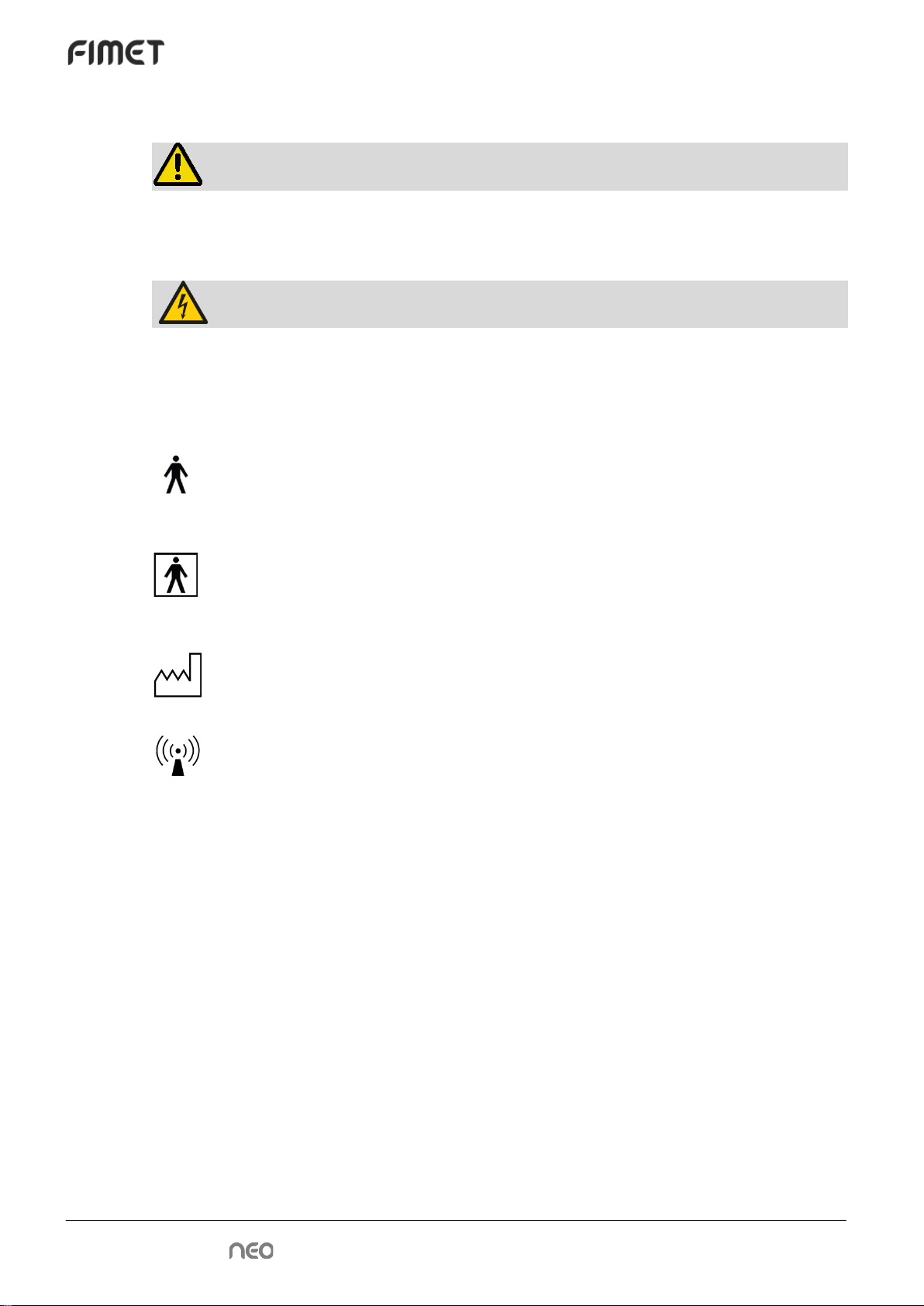
1.5 Symbols and Markings
Follow instructions for use
The information provided is important and must be read.
Note!
The information provided is important and should be read before use.
6 • Technical Manual
Warning!
This symbol warns against possible operating errors or hazards to the product, user, patient
or maintenance personnel.
Warning: High Voltage!
This symbol warns against high voltage. The system has to be separated from mains volt-
age before maintaining. Only qualified personnel may open the enclosure provided with this
symbol.
Type B classified applied part. It is a part which is in contact with the patient,
and might be protectively earthed or not conductive.
Type BF classified applied part. Offers better electrical protection than type B
applied part. BF applied parts are electrically separated from earth, ‘floating’.
2011 Manufacturing year.
RF transmitter, a symbol for non-ionising radiation. There is a low power
close-range RF transmitter in the remote foot control.
IPX1 Ingress protection code, class 1 means that the product is protected against
vertically falling water drops.
Italics mean a term or abbreviation with an explanation defined in the section 1.4
Terms and Abbreviations.
Bold text is a reference to another document.
1.6 Referred Documents
Registration Form – Supplied with the device.
Service Book – Located in the pouch on the backside of the unit door

Technical Manual • 7
1.7 General
Warning!: If this equipment is modified, appropriate inspection and testing
must be conducted to ensure continued safe use of the equipment.
Contact the manufacturer for detailed descriptions on printed circuit boards, component
lists, and other information and spare parts required to repair and service the equipment.
1.8 Transportation, Storage and Packaging
The patient chair and unit are delivered in separate packages.
Check the condition of the transport package before accepting the delivery. If the package
is damaged, please contact the carrier and report of the transport damage.
During transportation, the chair and unit packages may be stacked in piles of two. During
storage, piles of three are acceptable.
1.8.1 Symbols used in packages
Symbol
Instruction
Fragile, handle with care
Use no hand hooks
This way up
Keep away from rain
Stacking limit, number of packages allowed to be
stacked
Do not roll
Beware of scrathing the contents while opening the
package
0537
CE-mark with notified body number

8 • Technical Manual
1.8.2 Contents of the chair package
Item Order code Quantity
Neo Chair
1 pc
Seat upholstery
1 pc
Backrest
1 pc
Handle, right
1 pc
Handle, left
1 pc
Headrest
1 pc
Remote foot control
1 pc
Chair seat bottom back part
1 pc
Accessory box (+ other order specific items):
1 pc
Arm rest hole cover
59201011
2 pcs
Head rest lock tightening tool
59203610
1 pc
Chair bottom foot
59203660
5 pcs
PS Wafer 18*25*1,0
97601810
2 pcs
Screw 3 X 8
2 pcs
Screw 3 X 10
2 pcs
Screw 3 X 12
2 pcs
Screw 3 X 16
2 pcs
Screw 3 X 20
2 pcs
1.8.3 Contents of the unit package
Item Order code Quantity
Neo unit
1 pc
White spittoon bowl
C20171W
1 pc
Transparent spittoon bowl
C20171
1 pc

Technical Manual • 9
Item Order code Quantity
O-ring for spittoon bowl
OR7504
1 pc
Spittoon bowl sieve, lower
C20173
1 pc
Spittoon bowl sieve, upper
C20174
1 pc
All instrument flushing –holder
C10686
1 pc
Suction arm joint cap
C10548M
1 pc
Clean water bottle, 1l
32322301
1 pc
Unit accessory box
Adapter attachment screws, hex socket, M8x40
-
6 pcs
Adapter adjustment screws, hex socket, M8x30
-
6 pcs
Allen keys, 5 mm & 3 mm
-
2 pc
Suction hose, small volume, 2.03 m
99000010
1 pc
Suction hose, high volume, 1.96 m
99000009
1 pc
Suction hand piece, small volume
DU220 /
CA140 /
59205130
1 pc
Suction hand piece, high volume
DU210 /
CA150 /
59205090
1 pc
Suction tips for small volume suction
DU225
3 pcs
Suction hand piece tip
CA160
1 pc
Suction reduction piece, large
59204390
1 pc
Suction reduction piece, small
CA130
1 pc
General hose connector, white
59205471W
1 pc
Suction hose end piece, small, white
59205242W
1 pc
Suction hose end piece, large, white
59205241W
1 pc
Light pole via cover ring, white
59204274
1 pc
Block adjustment key
59204204
3 pc
PVC tube, Ø25mm x 100mm
-
2 pc
PVC connector 90° 32mm
PV03290
2 pc
Metal clamp for tube, 30mm
3333660
2 pcs
Compression fitting nut
3333190
2 pcs
Compression fitting ring
3333200
2 pcs
Lubricant for tube fittings
-
1 pc
Operating light pole cap
C10617
1 pc
Spring adjustment key
590208030
1 pc
Suction head attachment screw M8x18
-
1 pc
O-ring
OR156178
2 pcs
O-ring
OR12015
2 pcs
Tray arm stopper, white(*) (w. double tray)
59205200W
1 pc
Documents
Fimet Neo User Guide
1 pc
Instrument instruction manuals
n pc(s)
Neo Quick Guide
1 pc
10 • Technical Manual
Item Order code Quantity
Neo Registration card
1 pc
Neo Service book
1 pc
Neo monitor and camera power cable connections(*)
1 pc
* optional
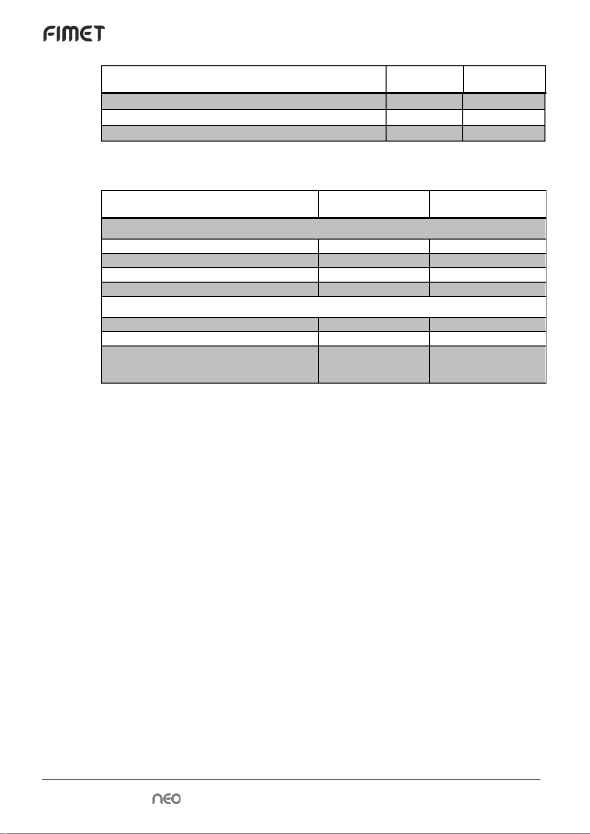
1.9 Environmental Specifications
Variable Min Max
During storage and transport
Humidity
10%
95%
Temperature
-40°C
70°C
Temperatures for display
-20°C
60°C
Air pressure
50 kPa (0.5 bar)
106 kPa (1.06 bar)
During use
Humidity
30%
75%
Temperature
10°C
35°C
Air pressure
80 kPa (0.8 bar, ca.
2000 m above sea
level)
102 kPa (1.02 bar, ca.
60 m below sea level)
Using the product in a moving vehicle is not allowed.
1.10 Maximum lifting capacity
The chair is designed to lift patients weighting 135 kg maximum. The total lifting capacity
(including the chair, patient, and other parts of the system) is 250 kg.
Maximum weight of the Display is 8 kg.
Technical Manual • 11
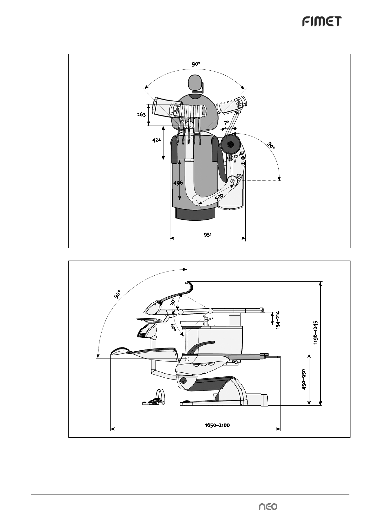
1.11 Movement Ranges

12 • Technical Manual
2 Installation
2.1 Space Requirements
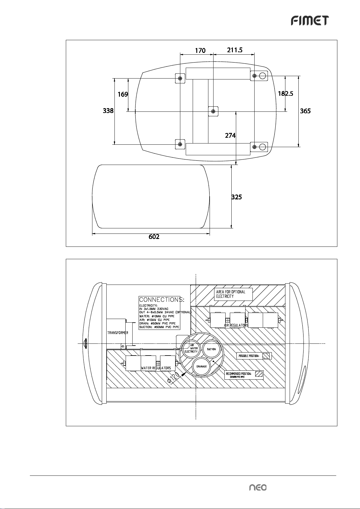
Technical Manual • 13
14 • Technical Manual
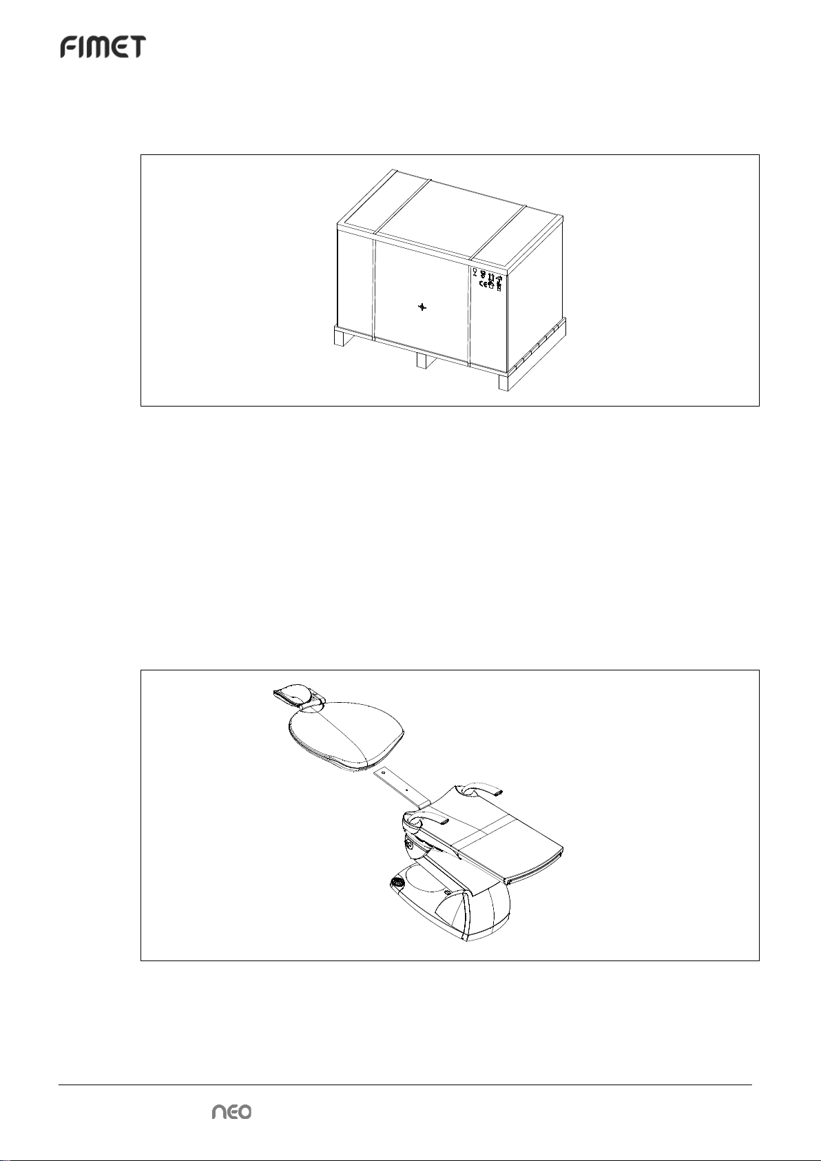
2.2 Unpacking
2.2.1 Unpacking the chair
After cutting the bands, lift the cardboard hood away.
Lift both of the trays away. Then lift the cardboard collar away. Unscrew the fixing screws.
The chair is now ready to be positioned to the final location. The side of cardboard box can
be used as a slide to ease up the positioning of the chair.
2.2.2 Unpacking the unit
Cut the bands and open the cardboard box. Remove the cardboard box. Detach the wood-
en frames around the unit. The unit is now ready to be attached to the chair.
2.3 Attaching Backrest
Slide the backrest in its place. Make sure the locking mechanism locks the backrest.

Technical Manual • 15
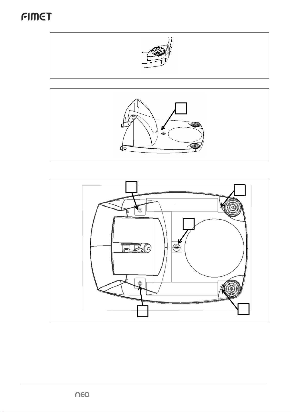
2.4 Attachment to floor
Remove screws A from both sides of the base.
Then detach the back cover. Now two out of five attachment screws are accessible.
Then push joystick inwards to uncover the screw hole. Then unscrew joystick attachment
screw and detach the joystick by lifting it carefully.
A
A
B
C
C
16 • Technical Manual
The C attachment screws are now accessible (4/5 in total).
The last attachment screw (3) is under a cover which can be detached using a suitable tool,
for example a coin.
Figure 1: Attachment bolts
The five attachment screws are located as shown in picture above.
B
3
1
5
2
4
Technical Manual • 17
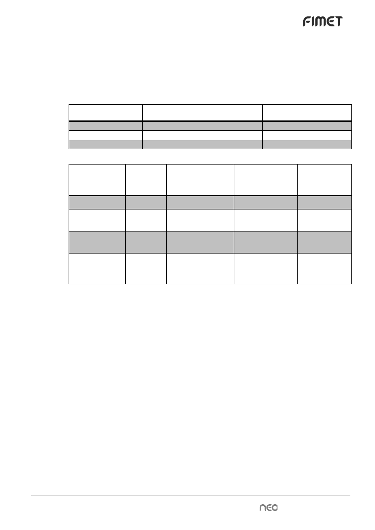
2.5 Floor materials
The Fimet Neo can be attached to different kinds of floors; for example floors made of con-
crete, wood, or gypsum. Table 2: Examples of attachments lists examples which are ac-
ceptable. The following table (Table 1: Minimum withdrawal strengths) shows the required
pulling strengths the attachment bolts have to withstand (withdrawal strengths).
Table 1: Minimum withdrawal strengths
Number of attachment
bolts
Attachment bolt places (see Figure 1:
Attachment bolts)
Minimum withdrawal
strength / bolt
1
[3]
2700 N
3
[1],[3],[5]
800 N
5
[1],[2],[3],[4],[5]
700 N
Table 2: Examples of attachments
Material of floor Number of
attachment
bolts
Attachment type Attachment hole
diameter and
depth
Withdrawal
strength / bolt
Concrete, K25 1 Würth Wümax 8x50 8 mm x 60 mm 3600 N
Concrete, K25 3,5 Würth Wümax Dome
6x40 6 mm x 45 mm 1200 N
Wood, 28 mm
solid wood floor 3,5 Hex Head Wood
Screw 6x40 6 mm x 45 mm 2000 N
Gypsum, 25 mm 5 Toggler Alligator –
anchor + WÜPO
General Screw 6x40
8 mm x 50 mm 775 N
2.6 Attaching unit to the chair
Slide the unit pallet next to the chair. Connect power cords from the unit to the chair tempo-
rarily to position the chair. Connect the connection box to the mains temporarily. Power up
the chair and position the height of the adapter (raise the chair) so that the unit can be
placed on it easily by sliding the pallet closer.
Attach the adapter. See chapter Adapter adjustments.

18 • Technical Manual
2.7 Adapter adjustments
Figure 2: Adapter with bolts
Attach the black hex screws. Adjust the cuspidor horizontally and vertically straight by loos-
ening the corresponding attachment screws. Ensure that at least 8 mm of the threaded part
of the bolt is inside the hole of the patient chair body plate. When the cuspidor is in the cor-
rect position attach and tighten the bright securing hex screws.
The black attachment hex socket (Allen) screws are of type M8 * 40, hardness 12.9, non-
galvanized. 6 pcs.
The bright securing hex socket (Allen) screws are of type M8 * 30, hardness 8.8, galva-
nized. 6 pcs.
2.8 Connecting the cables
Connect the cables
Figure 3: Chair connector PCB (CNA)
Black attachment
hex screw
Bright securing &
adjusting hex
screw
Screw for
grounding wire
Data bus con-
nector
Power connector
Technical Manual • 19
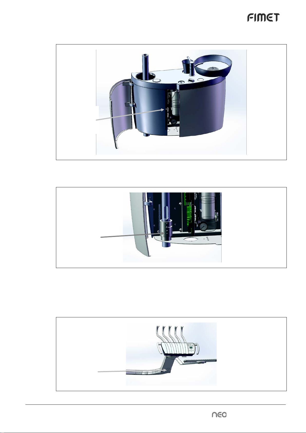
2.9 Removing transport screw
Figure 4: Electronics protection cover
Unscrew the attachment screw and remove electronics protection cover.
Figure 5: Transportation locking screw
Loosen the transportation locking screw. This screw prevents the rotation of the cuspidor
during transportation.
2.10 Adjusting the instrument arm spring
Transportation
locking screw
Electronics
protection
cover screw
Adjustment
opening cover

20 • Technical Manual
Figure 6: Instrument Arm spring adjustment
Remove the spring adjustment opening cover before adjusting the tension of the spring.
This adjusts the balance and displacement force of the instrument arm.
2.11 Adjusting the stiffness of tray rotation
Tray Arm
The stiffness of the rotation of the tray arm is adjusted with the adjustment screw (shown on
the picture). Use 3 mm hex key for the adjustment. The adjustment screw is locked with the
locking screw to prevent loosening. Use 4 mm hex key for the locking.
2.12 Headrest lock tightness adjustment
The movements of the headrest are double articulated. The headrest can be adjusted
around the two axels when the locking lever is in open position. The tightness of the locking
system is adjusted with a plastic tool delivered with the system.
Figure 7: Headrest lock tightening tool
Remove the plastic plug on the vertical bar carefully with the chisel end of the tool. Then
adjust the tightness of the nut with the key and replace the plug. The plug locks the tighten-
ing nut in its place.
Adjustment
screw
Locking
screw
Other manuals for NEO
1
Table of contents
Other Fimet Medical Equipment manuals


Popular Medical Equipment manuals by other brands


Getinge
Getinge Arjohuntleigh Nimbus 3 Professional Instructions for use

Mettler Electronics
Mettler Electronics Sonicator 730 Maintenance manual

Pressalit Care
Pressalit Care R1100 Mounting instruction

Denas MS
Denas MS DENAS-T operating manual

bort medical
bort medical ActiveColor quick guide

AccuVein
AccuVein AV400 user manual


