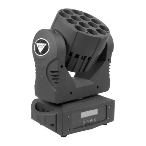
Fineart FINE 2000WASH-PERF User manual


http:// www.fineart-light.com
- 1 -
CONTENTS
Contents……………………………………………………………………1
FINE 2000 (FINE 2500) Wash Perf dimension diagram……………..3
Security Information……………………………………………………..4
Delivery……………………………………………………………………..5
Included items..………………………………………………………5
Transportation lock..…………………………………………………6
Single flight case..……………………………………………………6
Double flight case..…………………………………………………..6
Lamp..………………………………………………………………………7
Lamp introduction..…………………………………………………..7
Lamp replacement.…………………………………………………..7
AC power supply………………………………………………………….9
Fuses.…………………………………………………………………9
Power supply adjustment...…………………………………………9
Power connection…...…………………………………………….. 10
Data………………………………………………………………………..10
Connection equipment……………………………………………..11
Data link……………………………………………………………. 11
Rigging …………………………………………………………………...11
Equipment installation to stand...…………………………………11
Control panel…………………………………………………………….12
DMX address and protocol settings.……………………………..12
FINE 2000 (FINE 2500) Wash Perf functional introduction……………...... 13
Color...……………………………………………………………….13
Framing system.……………………………………………………14
Dimmer and Strobe...………………………………………………14
Strobe..………………………………………………………………14
Color temperature correction.……………………………………..14
Auto Zoom... ………………………………………………………..15
P/N 399903650601 VERSION A

http:// www.fineart-light.com
- 2 -
Iris…………………………………………………………………15
Pan/tilt.……………………………………………………………15
Speed control.……………………………………………………15
Controlling channels……………………………………………………16
DMX channels..…………………………………………………19
Menu control..……………………………………………………26
Routine maintenance…………..………………………………………32
Cleaning.…………………………………………………………32
FINE 2000(FINE 2500) Wash Perf channels diagram..……………33

http:// www.fineart-light.com
- 3 -
FINE 2000 (FINE 2500) Wash Perf dimension diagram

http:// www.fineart-light.com
- 4 -
Protection against explosion
Shields lenses and ultraviolet screens must be replaced if they
have become visible damaged to such an extent that their
effectiveness is impaired.
Replace the lamp immediately if it becomes visually deformed,
damaged or in any way defected.
Protection against electrical shock
Must disconnect the power supply when install, or remove of
bulbs, fuses and other components. Meanwhile using the ground-
ing must be closed to the ground.
Make sure that the mains power supply you use is up to local
construction and electronic code regulation, the over-load
protection earthing is essential.
Do not expose the device to rain or moisture.
All the equipment maintenance must be performed by a qualified
person with technical certificate.
Protection against ultraviolet radiation and light bulb explodes
Never operate the fixture with missing or damaged lenses and/or
covers.
Protecting your hands and eyes with
gloves and glasses, make the equipment
cool down at least 15 minutes.
Prolonged exposure to an unshielded
discharged lamp can cause eye and skin
burns.
Need to replace the broken bulb and the
bulb is to be replaced before the useful life.
Protection against burning or fire
Do not attempt to bypass the thermostat switch or fuse, replace
defective fuses with specified ratings only.
Keep flammable materials far away from the fixture (fiber, food,
and paper). Minimum distance from the flammable material is 1
meter.
Figure 1: pan/tilt lock

http:// www.fineart-light.com
- 5 -
Don’t illuminate surfaces within 3 meters of
the fixture. Projecting object in short
distance.
Ensure a minimum clearance of 0.1 meter
around the cooling fans and ventilations.
Do not place any filter or other object onto
the optical lens.
Allow the fixture to cool for at least 15
minutes before transit.
Do not revise the fixture or install any parts
not from Guangzhou CHAI YI LIGHT Co. Ltd.
When the ambient temperature exceeds 40 ℃,prohibit the use of
equipment.
Protection against injury due to falls
Do not lift or carry the fixture alone.
To inspect that the structure and the truss hooks
are in good condition and can bear about 10
times the weight of the fixture.
Ensure the cover and all riggings are securely
fastened, safety wire is necessary to use as a
secondary attachment.
To make the pulley lower than the
working position while installing or
dismantling the fixture.
Delivery
Important! Always open the horizontal and
vertical transport lock before use.
Included items
The FINE 2000 (FINE 2500) Wash
performance is packed with single or double
flight case. Included items show as below:
Figure 4: Open the rear cover
Figure 3: double transportation
Figure 2: single
transportation

http:// www.fineart-light.com
- 6 -
User manual 2 Suspension fasteners
Warranty card 1 Safety wire
1 Signal cable
Fuse configuration
Power
Fuse
200/250V
15A 6×30(main fuse)
6.3A 5×20(PCB board fuse)
3.15A 5×20(PCB board fuse)
10A 5×20(PCB board fuse)
100/120V
20A 6×30(main fuse)
6.3A 5×20(PCB board fuse)
3.15A 5×20(PCB board fuse)
10A 5×20(PCB board fuse)
Transportation lock
The head and arm can be locked during transport, locked location as
Figure 1. Open the lock before operation.
Single flight case
Dismantle the packaging
1. Unlock the flight case
2. Lift up the fixture by two men, each holding a lift handing, then
take it out from the flight case.
3. Open the horizontal and vertical transport lock before operation.
Fixture package
1. Cut off the power and cool down.
2. Lock up the head and arm (shown as figure 2)
3. Pack included items to the bottom of flight
case and then lock up the flight case.
Double flight case
Unpack
1. Open the flight case and pull out the drawer
2. Open the head vertical lock
3. Lift it by two men, each person for one side.
Figure 5: Unlit the lamp

http:// www.fineart-light.com
- 7 -
Package
1. Disconnect power and allow it to cool.
2. Turn the arm horizontally to the bottom so that it locks vertically from
the rear.
3. Pull out the drawer at its full length. Hang the fixture to the drawer
by two men, shown in Figure.3.
4. Lens cap faced the sidewall rather than door( as Figure.3). Then
lock the moving head(do not lock the horizontal lock)
5. Slide the drawer in and do not close the air box with violence.
Lamp
FINE 2000(FINE 2500)Wash Performance
Comes with OSRAM HMI/HTI 1200W/S
(1500W/S) or PHILIPS MSR GOLDTM
1510(1200)SA/DE discharge lamp. This lamp
offers color temperature 6000K, color rendering
index: larger than 90, life expectancy: 750 hours.
Only fixture of FINE 2000(FINE 2500)Wash Perf
incorporated with electronic ballast is capable of
hot re-strike.
The lamp sources features in a dedicate key on
a lamp end, as Figure 6
Warning! Don’t use other types of lamps instead of the intended ones,
otherwise safety hazards or damages to the fixture may arise.
The average life expectancy of the lamp is 750 hours, in order to
reduce the risk of damage to the lamp, should replace the lamp when
lamp life is in the use of more than 125%.
Lamp replacement
Important! Do not touch the quartz bulb of the lamp by bare hand,
always keep the lamp clean and free of oil, clean the lamp by alcohol
with a fry cloth, especially when you accidentally touch the bulb.
Replace bulb
Figure 6: install fixture

http:// www.fineart-light.com
- 8 -
1. Cut off the power and cool down
the fixture completely. Lock the
moving head when it’s horizontal.
2. As figure 4, CCW rotate the
screws on the lamp-access panel
by 90 degree with a flat-head
screw driver. Slide out the panel
and leave it still.
3. As shown in Figure 5, the left side
of the control spring up, pull out one end of the lamp, the other side
is also out of the hole.
4. As shown in Figure 6, put the gas nozzle backwards, and place the
new lamp in right side to the groove. Pull the spring of left side,
and then the place the other end of lamp.
5. Align the lamp with the slots in the reflector until they are on the
same plane. Slide the lamp inside and make sure the lamp will not
collide with the reflector, then screw up lamp-access panel.
6. Attention: When installing and removing the bulb, push the cover
gently along the slide bar and pull it out. Do not let the bulb touch
the reflector and the surrounding hard objects to prevent the bulb
from being damaged. (Figure 7)
Lamp adjustment
1. Turn on the power and wait for reset. Ignite the lamp through a
lighting controller or control panel. Then cast a beam on a plane at
least 3M away.
2. Adjust “UP-DOWN” screw with hex key
(=3MM), until highlight spot appear at
the flash centre.
3. If the illumination of the flash centre is
too bright, counterclockwise adjust
IN-OUT screws till brightness uniform.
If too dim, clockwise adjust “IN-OUT”
screws till brightness uniform(as figure 8)
Figure 8 adjust light
UP-DOWN
IN-OUT
Figure 7

http:// www.fineart-light.com
- 9 -
AC power supply
Warning! In prevention of electrical shock, the fixture must be well
earthed. Fuse applied in AC mains cords, leakage switch and
fault-earth protections are necessary.
Important! Inspect the supply apparatus before powering.
Mains fuses
There are 2 kinds for FINE2000(FINE2500) Wash Perf
Main fuse rating 20A with AC 100-120V
Main fuse rating 15A with AC 200-250V (Install fuse of the correct
rating in proximity to the main switch.)
Power supply adjustment
90-260V 50-60HZ for FINE 2000(FINE 2500) Wash perf
(electronic ballast)
00-250V 50/60HZ for FINE 2000(FINE 2500) Wash perf
( magnetic ballast)
FINE 2000(FINE 2500) Wash perf(electronic ballast)
90-260V 50-60HZ wide operating voltage range, a dedicated
range-setting switch (110V-220V) should be appropriately chose
based on the mains used.
An intelligent power functionality is extremely useful in the cases
when blackout caused by dimmer or superimposition of all CMY
filters over 3 seconds, the lamp power will be 700W. As a result, it
prolongs the lamp life as well as protecting color filters from high
temperature, and reduces the energy consumption.
FINE 2000(FINE 2500) Wash perf(magnetic ballast version)
Transformer and ballast used must conform to local supply
voltage and frequency. Fault installation may cause over-heat
damage or degrade its performance. Equipment intended to be
connected to mains supply has been marked for correct wiring.
Note: 100-120V power supply is not applicable for FINE 2000
Wash perf ( magnetic ballast)

http:// www.fineart-light.com
- 10 -
Power connection
Notice: Connecting the equipment to the power supply, do not
connect to silicon system, or else, it will destroy the equipment. The
fixture is provided with standard 3-pin socket. Please according to
below table connect to power supply, Yellow/Green line must be
earthed. If you still have any question to the installation, please
consultant with the experienced electrician.
When power is supplied, put the base switch to the position “I”.
Color
Wire
Mark
Brown
Live
L
Blue
Neutral
N
Yellow/Green
Earth
Data
Note! Do not connect more than one input and one output
FINE 2000(FINE 2500) Wash Perf has 3-pin and 5-pin plug connectors
for DMX inputs and outputs.All jacks are grounded with 1 pin, 2 pins
with negative polarity and 3 pins with positive polarity.
Connection equipment
Use an insulated twisted-pair shielded cable for the DMX 512
unit; standard loudspeaker cables can not reliably control
long-range data. 24AWG cable is for more than 300 meters. To
use long-distance signal transmission, you must join the DMX
512 signal amplifier.
Do not use two outputs to separate the connection. To isolate
this continuous connection component branch, use the DMX512
distributor.
Do not overload the connection, can be connected up to 32
devices in a continuous connection.
Terminate the connection by installing a terminal plug in the
output jack of the final fixture. The 0.25W 120Ω resistance
welding terminal plug 2, 3 pin, receiving control signal so that it

http:// www.fineart-light.com
- 11 -
does not reflect or cause interference. If you use a distributor,
please terminate each branch of the connection.
Data link
a) Connect the DMX input, from the controller to the 3-pin socket
of FINE2000 (FINE2500) Wash perf.
b) Use the plug that matches the data cable to connect the
output of the nearest device to the next device input.
c) Make the plug which will match the 120Ω terminal plug
inserted into the last device 3 pin socket output.
Rigging
FINE 2000 (FINE 2500) Wash Perf can be placed on the stage or
installed in the bracket of any direction. With fast lock system, four
directions of Figure 9 can be locked on the bracket quickly and easily.
Figure 9 Fixture holder position
Warning!
To secure the unit with 2 clamps, turn 1/4 turn clockwise to lock the
fastener. Adding a safety rope connected to the hole in the base, be
careful not to connect to the transport handle.
Equipment installation to stand
1. To inspect the truss hook/rigging are in good condition and can
bear about 10 times the weight of the light fixture. Be sure the truss or
pipe construction can bear 10 times the weight of all equipment of all
equipment including lights, truss hooks, cables and accessories.
2. Lock bracket by M12 screws and nuts.

http:// www.fineart-light.com
- 12 -
3. Install a clamp point in the base, insert the fasteners into the base
and turn the two levers a full 1/4 buckle clockwise to lock it completely,
and install the second clamp in the same way.
4. If the truss can be lift down, the light fixture can be lifted and
hooked from flight case directly. When the lights equipments need to
lift high, the working area below should have some barrier to ensure
the installation works operated under safety condition. Finally suspend
the fixture onto the truss, let the arrows point in the projection direction,
and fasten clamps totally. (figure 10)
5. Connect a safety rope which can bear 10 times weight of the
fixture, the attachment is designed to fit a clamp.
6. Check the horizontal and vertical locks have been unlocked, be
sure there is no explosive or inflammable materials around the fixture
in 1meter around.
Control panel
LCD controlling panel for address setup and property setup
DMX address and protocol settings
DMX address, also known as the start channel, is an indication
channel used to receive the controller and is controlled individually. If
you want the same action, address sharing can be used for diagnostic
purposes, symmetrical control, especially in combination with
horizontal vertical position inversion.
About personality setup, please refer to the menu control in the user
manual.
Picture 10

http:// www.fineart-light.com
- 13 -
When fitting a color
filter or gobo, the
coated side should
face the lamp
source
FINE 2000(FINE 2500)WA PERF Functional Introduction
Color
The color mixing system consist dichroic cyan, magenta and yellow
(CMY) color filters. It is a subtractive system that removes color
components from the white light.A full superimposition of all CMY
filters results in blackout. For the maximum brightness of the color
mixture can be mixed with two colors.
Color wheel I: Color wheel II:
Color filter 1: green Color filter 1: dark red
Color filter 2: dark blue Color filter 2: orange
Color filter 3: UV Color filter 3: dark green
Color filter 4: pink Color filter 4: blue
Color filter 5: white light Color filter 5: white light
The color system consist two color wheels (gobo wheel 2 can change
to glass gobos), each equipped with 4 interchangeable filters through
which easier and quicker color transferred can be achieved.
Color wheel 2 can change gobos

http:// www.fineart-light.com
- 14 -
Framing system
FINE 2000 (FINE 2500) Wash PERF comes with a framing module,
which can be swiveled by 90°through synchronous belt drive. Four
interleaved framing blades, each driven by stepping motor, are
capable of panning +/-30°. Combination of displacements and pan of
four individual blades bring up unlimited shades, rectangle, diamond,
triangle, etc. Besides, 90°swiveling range of the whole framing
module make it possible to rotate the above shades at any angle, a
perfect means of setting up scenes for theatre.
The iris module is attached to the framing module, thus it can work
independently or swivel in conjunction with the framing module.
Dimmer and strobe system
Two dimmer system——internal machine dimmer/ strobe
system(shutter),one dimmer wheel for option(customed indivudual)
Strobe system
0—100% electromotion dimmer,on/ off instant, convert by random,can
strobe to 10HZ, random and varibalefrequency can control the dimmer
machinturn onm slowly and fade away or off, then turn on slowly.
CTC (color temperature correction)
The CTC system applies a specific color filter by which it can lower CT
(color temperature) from 6500K to 2900K.
Framing system

http:// www.fineart-light.com
- 15 -
Auto zoom
Zoom lens beam range:24°-40°, use standard lens and iris system
Iris
The minimum diameter of the aperture only amounts to 15% of its full
open diameter. Strobe effects can be achieved through setting up
opening/closing speeds. (200-step resolution).
Pan/tilt scan
Pan scan 540°tilt scan 255°, if you need more accurate positioning,
please choose 16bit.
Pan/tilt speed(fast、normal、slow)can set by speed selection in menu.
Speed control
Speeds from actuating to normal working are controllable. Tracking
tracing comes along by setting “pan/tilt speed” channel and “effect
speed” channel. These channels are independent.
Open iris by the ways as follow:
for an instant case of track tracing, fade out previous scene after
aperture completely close, then reset a new scene before the aperture
fully open. If preset interval for this cycle is 10 seconds, an initial value
199(aperture fully close) will reduce to 0(aperture fully open) within the
interval, a controller regulates the aperture closing or opening in
accordance with the value varied.

http:// www.fineart-light.com
- 16 -
Controlling channels
Control channel:45 control channels mode and 28 control channels
45 control channels mode function:
Channel 1:Strobe
Channel 2:Dimmer
Channel 3:Dimmer 16bit
Channel 4:Pan rotation
Channel 5:Pan rotation 16bit
Channel 6:Tilt rotation
Channel 7:Tilt rotation 16bitI
Channel 8:Pan/tilt speed adjustment
Channel 9:Pan/tilt macro function
Channel 10:Pan/tilt macro speed
Channel 11:Blade 1 pan
Channel 12:Blade 1 pan16bit
Channel 13:Blade 1 moves inwards/outwards
Channel 14:Blade 1 moves inwards/outwards 16bit
Channel 15:Blade 2 pan
Channel 16:Blade 2 pan 16bit
Channel 17:Blade 2 moves inwards/outwards
Channel 18:Blade 2 moves inwards/outwards 16bit
Channel 19:Blade 3 pan
Channel 20:Blade 3 pan 16bit
Channel 21:Blade 3 moves inwards/outwards
Channel 22:Blade 3 moves inwards/outwards 16bit
Channel 23:Blade 4 pan
Channel 24:Blade 4 pan 16bit
Channel 25:Blade 4 moves inwards/outwards
Channel 26:Blade 4 moves inwards/outwards 16bit
Channel 27:CMY cyan
Channel 28:CMY cyan 16bit
Channel 29:CMY magenta

http:// www.fineart-light.com
- 17 -
Channel 30:CMY magenta 16bit
Channel 31:CMY yellow
Channel 32:CMY yellow 16bit
Channel 33:CTC color temperature
Channel 34:CTC color temperature16bit
Channel 35:Zoom
Channel 36:Zoom 16bit
Channel 37:Iris
Channel 38:Blade rotation
Channel 39:Color 1
Channel 40:Color 2
Channel 41:Color macro function
Channel 42:Speed effect adjustment
Channel 43:CMY macro function
Channel 44:Lamp half power selection
Channel 45:Fan control
28 control channel function:
Channel 1:Strobe
Channel 2:Diming
Channel 3:Pan rotation
Channel 4:Pan rotation 16bit
Channel 5:Tilt rotation
Channel 6:Tilt rotation 16bit
Channel 7:Pan/tilt speed adjustment
Channel 8:Pan/tilt macro function
Channel 9:Pan/tilt macro speed
Channel 10: Blade 1 pan
Channel 11:Blade 1 moves inwards/outwards
Channel 12:Blade 2 pan
Channel 13:Blade 2 moves inwards/outwards
Channel 14:Blade 3 pan

http:// www.fineart-light.com
- 18 -
Channel 15:Blade 3 moves inwards/outwards
Channel 16:Blade 4 pan
Channel 17:Blade 4 moves inwards/outwards
Channel 18:CMY cyan
Channel 19:CMY magenta
Channel 20:CMY yellow
Channel 21:CTC color temperature
Channel 22:Zoom
Channel 23:Iris
Channel 24:Blade rotation
Channel 25:Color 1
Channel 26:Color 2
Channel 27:Color macro function
Channel 28:Speed effect adjustment

http:// www.fineart-light.com
- 19 -
DMX Channels Opening code =0
28
channel
45
channel
Value
Percentag
e
Function
1
1
0-19
20-49
50-72
73-79
80-99
100-119
120-127
128-147
148-167
168-187
188-190
191-193
194-196
197-199
200-202
203-207
208-217
0-17
8-19
20-28
29-31
31-39
39-47
47-50
50-58
58-65
66-73
74-75
75-76
76-77
77-78
78-79
80-81
82-85
Strobe
Shutter, close
Open
Strobe, fast→slow
Shutter open
Strobe open, fast→slow
Strobe close, fast→slow
Shutter open
Random Strobe, fast
Random Strobe, medium
Random Strobe, slow
Shutter open
Random opening pulse, fast
Random opening pulse, slow
Random closing pulse, fast
Random closing pulse, slow
Shutter, open
Fixture reset
2
2
0-255
0-100
Dimming 0%-100%
-
3
0-255
0-100
Dimming 16bit
3
4
0-255
0-100
Pan rotation
4
5
0-255
0-100
Pan rotation 16bit
5
6
0-255
0-100
Tilt rotation
6
7
0-255
0-100
Tilt rotation 16bit
This manual suits for next models
1
Table of contents
Other Fineart Lighting Equipment manuals
Popular Lighting Equipment manuals by other brands

Govee
Govee H61E0 user manual
Federal Signal Corporation
Federal Signal Corporation 151XST Series Installation and maintenance manual
WiSilica
WiSilica Lumos Controls Iris E user guide
LDR
LDR Nota f1200 XL black operating instructions
Velleman
Velleman HQ POWER VDL25ST user manual
XanLite
XanLite PRS900D user manual
