IOG 2800.80 2
Model
Modelo C14-VS-**
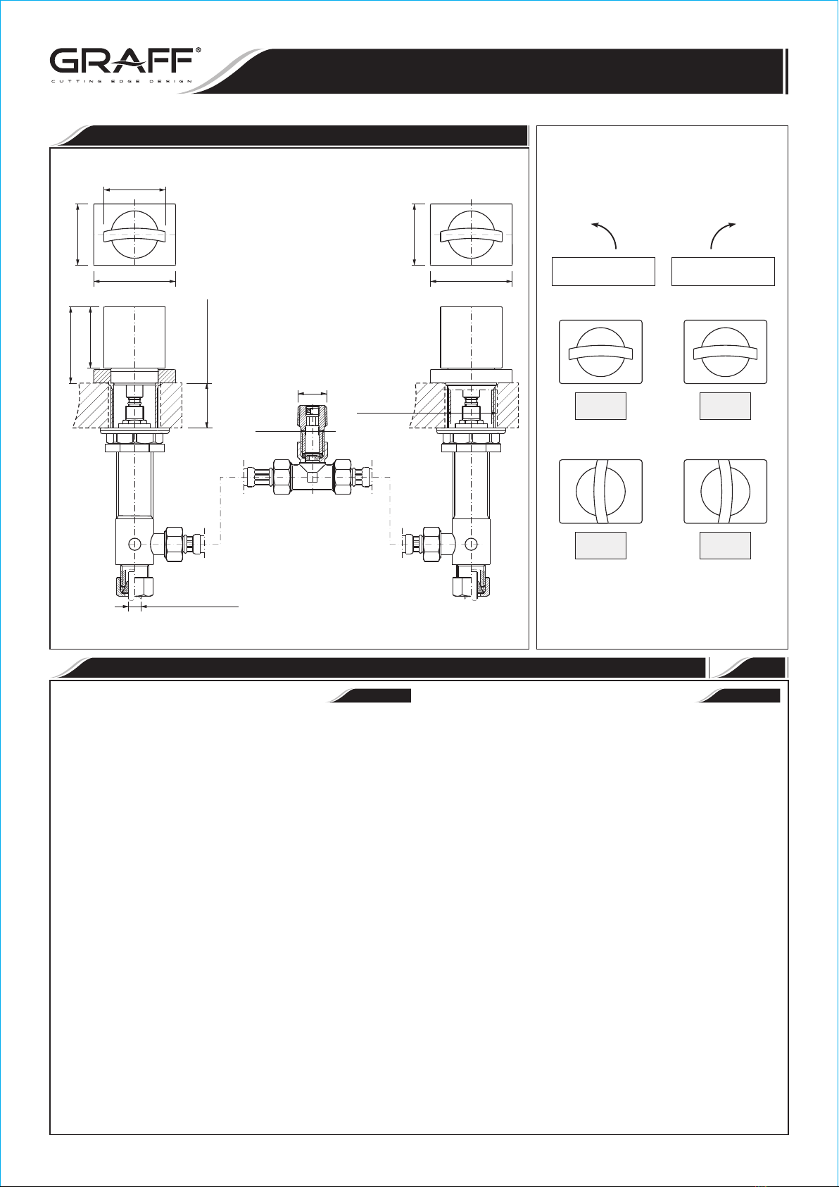
HANDLES ASSEMBLY • ENSAMBLE DE LOS MANILLAS
* – type of finish
* – tipo de acabado
Installation Instructions Instrucciones de Instalación
HANDLES ASSEMBLY
ENSAMBLE DE LOS MANILLAS
On
Abierto
Off
Cerrado
¼ turn
¼ de vuelta
Counterclockwise opening
Se abre hacia la izquierda
On
Abierto
Off
Cerrado
Clockwise opening
Se abre hacia la derecha
¼ turn
¼ de vuelta
5/16"
1/2NPT
MAX. 1-1/2"
(MAX. 38mm)
1-7/8"
(48mm)
2-3/8" (60mm) 1-7/8"
(48mm)
1-7/8"
(48mm)
2-1/2"
(64mm)
2-1/2"
(64mm)
1-7/8"
(48mm)
Ø1-1/2"
(Ø38mm)
Ø3/8" (Ø9.5mm)
~
ESPANOL
ENGLISH
HANDLES INSTALLATION INSTALLACIÓN DE LAS MANILLAS 1
See fig. 2.1-2.2, 3.1-3.4
1) Place handle base (2) and center over side hole of mounting surface -
see fig. 1 and 3.1.
2) Insert handle assembly (1) into the hole of a handle base (2) and a
deck. From underneath the lavatory place the washer (3) and then
screw the flanged nut (4) (fig.3.1).
3) Set the handle as on fig. 1 - “OFF” position.
4) Turn the spline of a cartridge in a valve (6R) & (6L) to OFF
position:
•in the hot water valve (fig. 2.1): left valve marked with the red
sticker turn the cartridge spline (A) in clockwise direction,
•in the cold water valve (fig. 2.2): right valve marked with the blue
sticker turn the cartridge spline (B) in counterclockwise direction.
5) Turn onto the valve (6R) & (6L) counter nut (10) (fig. 3.2).
6) Holding the valve with the outlet pointing towards you (in case of hot
water valve) (6L) / or outwards (in case of cold water valve (6R))
put the valve into the handle assembly (1), so the spline of the
cartridge mates with the spline of the handle (fig. 3.2).
7) Thread in the valve home, then release the valve 0.5 to 1.5 turn.
Position the handle (1) as on fig. 1. Tighten lightly the counter nut
(5) on the valve (fig. 3.3).
8) Note the position of the outlet of the valve and make sure it fits the
flexible hose connection (10). If it is ok tighten the counter nut
(5) - see fig. 3.4, if not move the valve by the required angle.
To achieve this do the following:
•unscrew the valve without disconnecting the handle,
•hold the handle,
•disconnect the valve from the handle,
•rotate the valve by required angle,
•connect the valve to the handle as described above,
•secure the handle and the valve with the counter nut (5).
Ver dis. 2.1-2.2, 3.1-3.4
1) Coloque la base de la manilla (2) y centre en el agujero lateral de la
superficie de montaje - ver dis. 1 y 3.1.
2) Poner el juego de manilla (1) al agujero de la base de la manilla (2) y
de la superficie de montaje. Colocar la arandela por debajo del lavabo
(3) y atornillar la tuerca con brida (4) (dis. 3.1).
3) Poner la manilla como en el dib. 1 en la posición “OFF”.
4) Poner la polichaveta del cartucho en la válvula (6R) y (6L) en la
posición “cartucho cerrado” - “OFF”:
•en el caso de la válvula de agua caliente (dis. 2.1): la válvula
izquierda con etiqueta roja con cartucho cerrado a la derecha -
girar la polichaveta del cartucho (A) a la derecha,
•en el caso de la válvula de agua fría (dis. 2.2) válvula derecha con
etiqueta azul con cartucho cerrado a la izquierda - girar la
polichaveta del cartucho (B) a la izquierda.
5) Atornillar en la válvula (6R) y (6L) la tuerca de contra (10) (dis.
3.2).
6) Teniendo la válvula con su salida hacia sí (en el caso de la válvula de
agua caliente, (6L) / hacia fuera (en el caso de la válvula de agua fría
(6R) ), ponerla a la manilla (1), la polichaveta del cartucho se
engranará con la polichaveta de la manilla (dis. 3.2).
7) Enroscar la válvula a su máximo y después retirar la válvula a 0.5
hacia 1.5 de la rotación. Poner la manilla (1) como en el dib. 1.
Apretar ligeramente la tuerca de contra (5) en la válvula (dis. 3.3).
8) Recordar la posición del escape de la válvula y estimar si concuerda
con la manguera flexible (10). Si concuerda, atornillar la tuerca
de contra (5) - ver el dis. 3.4., si no concuerda; reponer la
válvula teniendo en cuenta el ángulo adecuado. Para hacer eso:
•destornillar la válvula sin desconectarla con la manilla,
•sujetar la manilla,
•desconectar la válvula de la manilla,
•reponer la válvula hacia su ángulo adecuado,
•conectar la válvula con la manilla teniendo en cuenta lo susodicho,
•proteger la manilla y la válvula con la tuerca de contra (5).
Rev. 2 April 2015


