FireFlex VACTEC Installation guide

FM-060M-0-110A
Advanced Integrated Fire Protection System
Owner's Operation
and
Maintenance Manual
DRY-PIPE VACUUM SPRINKLER SYSTEM
ELECTRIC RELEASE

Page ii
Integrated Fire Protection System
OWNER'S OPERATION &MAINTENANCE MANUAL
FM-060M-0-110A
Manufactured by FIREFLEX Systems Inc.
1935 Lionel-Bertrand Blvd
Boisbriand, QC (Canada) J7H 1N8
Tel: (450) 437-3473 Toll free: (866) 347-3353
Fax: (450) 437-1930
Page iii
Integrated Fire Protection System
O
WNER
'
S
O
PERATION
&
M
AINTENANCE
M
ANUAL
FM-060M-0-110A
Table of Contents
Dry-pipe Vacuum Sprinkler System - Electric Release
General Section............................................................................................................................ Section A
1- General description
2- Listings and approvals
3- Applicable standards
4- Environment
5- Features
6- Configuration description
7- System release
Mechanical Section...................................................................................................................... Section B
1- Installation, operation and instruction
1.1 Installation
1.2 Preliminary inspection before placing the system in service
1.3 Placing the system in service
1.4 System operation
1.5 Emergency instructions
1.6- Placing system back in service after operation
1.7 Inspections and tests
1.8 Maintenance
2- Trim Schematics
Trim Options................................................................................................................................. Section C
1- Semi & full flange option
Vacuum Supply Section.............................................................................................................. Section D
1- Vacuum supply
1.1 Operation
1.2 Pressure settings
1.3Maintenance and inspection
Controls Section ...........................................................................................................................Section E
1- Release control panel
2- Vacuum pump control box
Electrical Section .........................................................................................................................Section F
1- Operation
2- Electric release programming
3- FLX-PC®pressure controller
4- Optional modules
Dimensional Data & Cabinet.......................................................................................................Section G
1- Cabinet for FIREFLEX®VACTEC®unit
Limited Warranty ......................................................................................................................... Section H

Page iv
Integrated Fire Protection System
OWNER'S OPERATION &MAINTENANCE MANUAL
FM-060M-0-110A
Copyright ©2017 FIREFLEXSystems Inc.
All Rights Reserved
Reproduction or use, without express written permission from FIREFLEX Systems Inc, of any portion of this manual is prohibited.
While all reasonable efforts have been taken in the preparation of this manual to assure its accuracy, FIREFLEX Systems Inc
assumes no liability resulting from any errors or omissions in this manual, or from the use of the information contained herein.
FIREFLEX®is a registered trademark of FIREFLEX Systems Inc. VACTEC®is a registered trademark of VACTEC Vacuum
Technology.
FIREFLEX Systems Inc. reserves the right to make changes to this manual and the data sheets herewith at any time, without prior
notification.

Page 1 of 2
Integrated Fire Protection System A
General Section - Dry-pipe Vacuum Sprinkler System - Electric Release
FM-060M-0-111B
1- General description
Dry-pipe vacuum sprinkler system uses closed vacuum
sprinklers specified for vacuum use with vacuum sprinklers
piping network.
This FIREFLEX®VACTEC® integrated fire protection system
consists of a vacuum system trim totally pre-assembled,
pre-wired and factory tested. All electrical and mechanical
components of the system are contained in one single unit.
The only connections required for installation are the water
supply inlet, water discharge outlet, main drain, as well as
the AC power line(s) and alarm connections. The
discharge outlet is connected to a fixed vacuum sprinklers
piping network. Water is the extinguishing agent.
The FLX-PC® VACUUM / PRESSURE CONTROLLER allows the
release control panel to receive the appropriates alarm
and supervisory signals which supervises the vacuum
pressure and activates discharge condition. It also
controls the vacuum pump operation. For more
information, refer to FLX-PC® VACUUM / PRESSURE
CONTROLLER at section F .
Note: Every FIREFLEX®VACTEC® unit is identified with its
unique serial number. This number is located on an
adhesive label inside the main door panel and is used to
maintain a record in our computerized data base. Have
this serial number handy when calling for information on
your unit (format is VAC # # # # #).
2- Listings and approvals
In addition to being fabricated under tight ISO-9001
manufacturing and quality control procedures, your
FIREFLEX®VACTEC® unit by FIREFLEX Systems Inc. has
also been tested and approved by recognized laboratories.
Here is the list of listings & approvals it meets:
- Pending Factory Mutual Research <FM>:
FIREFLEX®VACTEC® vacuum systems are FM Approved
under the heading: "Automatic Water Control Valves"
when installed with specific components.
Note: Although most FIREFLEX®VACTEC® units are listed
and approved, custom built units are sometimes supplied
on request. Components in these special units maintain
their individual listings/approvals but the units are not listed
as an assembled unit.
Warning ! Any unauthorized modification or addition made
on-site to a factory built listed unit will void this listing.
Such modifications or additions may void the unit's
warranty as well. Consult your nearest FIREFLEX Systems
Inc. authorized distributor before proceeding with such
modifications or additions.
3- Applicable standards
The FIREFLEX®VACTEC® complies with the following
standards:
- NFPA-72 Fire Alarm Systems
Before installation, the contractor installing the unit shall
also be familiar with the following documents and
standards:
- Applicable local & state building codes
- Any additional requirements of the local authority having
jurisdiction
4- Environment
The FIREFLEX®VACTEC® unit shall be installed in a dry and
clean location. Verify that all equipment is properly heated
and protected to prevent freezing and physical damage.
The unit and its components must be kept free of foreign
matter, freezing conditions, corrosive atmospheres,
contaminated water supplies, and any condition that could
impair its operation or damage the components.
The frequency of the inspections and maintenance will
vary depending on these environmental conditions as well
as the condition of the vacuum supply to the system. The
owner is responsible for maintaining the fire protection
system and devices in proper operating condition. Refer to
section B MECHANICAL SECTION for maintenance
instructions.

Page 2 of 2
A
Integrated Fire Protection System
General Section - Dry-pipe Vacuum Sprinkler System - Electric Release
FM-060M-0-111B
5- Features
The FIREFLEX®VACTEC® unit is superior to many other
products available on the market now, and has been
proudly manufactured by the company that has introduced
and developed the concept of integrated fire protection
systems in the market.
Main features are:
Trouble free design for safe and easy application
Available in 4 sizes from 3" to 8" diameter
Uses the Viking deluge valve
Unit comes standard with its owned integrated releasing
control panel
Uses the FLX-PC® VACUUM / PRESSURE CONTROLLER
Compact, aesthetic and easy to move
User-friendly standardized owner's manual with every
unit
Unique serial number on every unit
Trim is fully assembled and tested at the factory
All trims are galvanized steel, listed and approved for
175 PSI (1207 kPa) service maximum
Quick connections to water supply and drain on both
sides, and vacuum sprinklers riser on top of unit, all
available with grooved end or optional flanged fittings
Shut-off valve at the outlet of the vacuum sprinklers riser
for easier maintenance
No open drain cup inside unit
Sturdy 14 gauge steel cabinet, painted fire red with oven
baked polyester powder on phosphate base
Textured rust proof finish
Neoprene gasket on all doors to eliminate vibrations
Removable doors for ease of access
Separate unlocked access hatch to emergency manual
release
Key-alike locks on all cabinet doors
Manufactured under ISO-9001 quality control procedures
6- Configuration description
The FIREFLEX®VACTEC® system is built around the Viking
deluge valve Model F-1.
Each system is rated up to a maximum of 175 PSI WWP
(1207 kPa) max. and are available in the following
diameters:
3" (75 mm) 6" (150 mm)
4" (100 mm) 8" (200 mm)
The FIREFLEX®VACTEC® unit is supplied with groove/
groove deluge valve. Unit with flange/flange deluge valve
is also available upon request.
6.1 Dry-pipe Vacuum Sprinkler System
Note: Numbers indicated between brackets refer to items
on the TRIM SCHEMATICS from section B MECHANICAL and
section D VACUUM SUPPLY.
The vacuum sprinklers piping network is under vacuum
pressure. This dry-pipe vacuum sprinkler system utilizes a
Viking deluge valve (A1) which opens by the operation of
the solenoid valve (F1) or the manual emergency release
valve (B10).
The vacuum level inside the piping network is supervised
by the FLX-PC® VACUUM / PRESSURE CONTROLLER for low,
high and alarm vacuum levels. One objective of this
device is to perform the opening of the deluge valve in less
than 5 seconds following the opening of a vacuum
sprinkler, thereby permitting a more rapid fire attack.
The electric release system operates by the alarm
pressure of the FLX-PC® VACUUM / PRESSURE CONTROLLER.
If a vacuum sprinkler is fused, or damage to a vacuum
sprinkler or to piping network occurs, the FLX-PC® will
operate and the deluge valve (A1) will open, flowing water.
The electric release system also operates when a manual
pull station is triggered, opening the deluge valve (A1).
Water will be contained in the piping network until the
opening of a vacuum sprinkler.
In the event of no operation of the electric release system
or if the release control panel is no more powered from AC
power and batteries, the dry-pipe vacuum sprinkler system
can be manually trip by triggering the manual emergency
release valve (B10), causing the deluge valve (A1) to
open. Water will be contained in the piping network until
the opening of a vacuum sprinkler.
7- System release
7.1 Electric release
Electric release trim for dry-pipe vacuum sprinkler system
utilizes an electric solenoid valve (F1) controlled by the
approved release control panel provided with this system
(see section E CONTROLS and VFR-400 manual for
details).
In fire condition, when a vacuum sprinkler is fused, or
damage to a vacuum sprinkler or to piping network occurs,
an alarm pressure signal from the FLX-PC® VACUUM /
PRESSURE CONTROLLER to the release control panel
energizes the solenoid valve (F1), causing the deluge
valve (A1) to open. Water will flow from the previous
opening.
When a manual pull station is triggered, the release control
panel energizes the solenoid valve (F1), causing the
deluge valve (A1) to open. Water will be contained in the
piping network until the opening of a vacuum sprinkler.
Page 1 of 10
Integrated Fire Protection System
B
Mechanical Section - Dry-pipe Vacuum Sprinkler System - Electric Release
FM-060M-0-112B
1- Installation, operations & instructions
Note: Numbers indicated between brackets refer to
figures 1 and 2 SIMPLIFIED and DETAILED SYSTEM TRIM
SCHEMATICS from this section and section D VACUUM
SUPPLY.
1.1 Installation
1. Conform to local municipal or other codes regarding
installations of fire protection systems. Refer to
FIREFLEX®Design Manual for vacuum sprinklers piping
installation.
2. Install the FIREFLEX®VACTEC®unit and connect the
system according to instruction manual and technical
data supplied.
Note: The drain collector shall be connected to an open
drain. Do not restrict or reduce drain piping.
3. Install the vacuum sprinklers piping network and
vacuum sprinklers in accordance with applicable
standards.
4. Connect alarm audible devices, where applicable,
according to electrical schematics (see field wiring
diagram in section F ELECTRICAL).
5. Connect the AC power to the release control panel and
the vacuum pump on two separate breakers in the
electric distribution panel (see field wiring diagram in
section F ELECTRICAL).
Notes:
AC power connections must be made by a qualified
installer according to national standards.
Do not apply AC power to the release control panel and
the vacuum pump yet.
6. Perform preliminary inspection as outlined in
paragraph 1.2 of the current section prior to putting
system in service.
7. Place the system in service as outlined in paragraph 1.3
of the current section.
8. Perform the annual inspection sequence and test alarm
unit.
9. If the system does not operate as it should, make the
necessary corrections according to manuals issued or
consult your distributor or FIREFLEX Systems Inc.
10. Make sure that building owner or a delegated
representative has received instructions regarding the
operation of the system.
WARNING ! FIREFLEX®VACTEC®unit must be installed in an
area not subject to freezing temperatures or physical
damage.
1.2 Preliminary inspection before placing the system in
service
1. Open door to mechanical section.
a) Main water supply valve (D1) must be CLOSED.
b) Priming valve (B1) must be CLOSED.
c) Flow test valve (B6), main drain valve (D3) and
system drain valve (G10)must be CLOSED.
d) Alarm test valve (B5) and alarm line drain valve (B7)
must be CLOSED.
e) Manual emergency release valve (B10)must be
CLOSED.
f) Vacuum supply must be CLOSED (see section D
VACUUM SUPPLY).
g) Gauges (B11 and B12) should show 0 PSI (0 kPA).
h) The shut-off valve (D4)must be OPEN.
2. Using the built-in contractor's hydrostatic test ports (see
figure 2 DETAILED SYSTEM TRIM SCHEMATIC of the current
section for location), fill vacuum sprinklers piping
network with water and maintain pressure as per
NFPA-13 requirements.
WARNING ! Do not subject the pressure gauges and
pressure transducer to hydrostatic pressure above 250 PSI
(1724 kPA). Close gauge valves before proceeding with
hydrostatic test.
3. Correct leaks if any before completing test.
4. Verify that main water supply valve (D1) is CLOSED.
OPEN main drain valve (D3), alarm drain valve (B7) and
system drain valve (G10)to completely drain the
vacuum sprinklers piping.
5. Apply AC power to the release control panel and the
vacuum pump (see section F ELECTRICAL).
6. Install and connect the batteries. Observe battery size
and polarity.
For battery capacity calculations, see the VIKING VFR-400
INSTALLATION, OPERATION AND INSTRUCTION MANUAL
provided with the FIREFLEX®VACTEC®unit. Don't forget to
add the current consumption of the FLX-PC®(G18).
7. Reset the release control panel and silence the alarm.
Note: Batteries shall be installed with the control panel at
hanged position. Battery compartment should always stay
closed while rotating the control panel.
8. The FLX-PC® (G18) VACUUM / PRESSURE CONTROLLER
should show 0 mBAR (0 kPA).

Page 2 of 10
B
Integrated Fire Protection System
Mechanical Section - Dry-pipe Vacuum Sprinkler System - Electric Release
FM-060M-0-112B
1.3 Placing the system in service
1. Verify that all vacuum sprinklers are set and that
inspector's test valve and/or piping auxiliary drain valves
are CLOSED.
2. Verify that the system has been properly drained (see
warning note below). CLOSE main drain valve (D3),
system drain valve (G10) and alarm line drain
valve (B7). Verify that the manual emergency
release (B10) is CLOSED.
Warning ! It is very important to properly drain the piping
network in order to reduce the effect of corrosion.
3. Turn on the vacuum pump switch (G16) (see
section D VACUUM SUPPLY).
The sign [] will be displayed on the FLX-PC®(G18)
when the pump is running and excess water in deluge
valve (A1) will be drained by vacuum pump (G1).
4. When vacuum pump (G1) stops, solenoid valve (G2)
should close. FLX-PC®(G18)should display vacuum
level.
5. OPEN priming valve (B1).
6. Reset the release control panel. Solenoid valve (F1)
should close. Water pressure rises slowly on
gauge (B11). Silence the alarm.
7. OPEN flow test valve (B6). PARTIALLY OPEN main water
supply valve (D1).
Note: Do not open main water supply valve (D1)until
gauge (B11) shows stabilized pressure.
8. When full flow develops from the flow test valve (B6),
CLOSE the flow test valve.
9. FULLY OPEN the main water supply valve (D1). Reset
the release control panel.
10. Verify that the alarm test valve (B5) is CLOSED and that
all other valves are in their "normal" operating position
(refer to paragraph 2.2 NORMAL CONDITION of the current
section for details).
11. Check and repair all leaks.
12. On new installation, system that has been placed out of
service, or where new equipment has been installed, trip
test the system to verify that all equipment functions
properly. Refer to paragraph 1.7.2 INSPECTIONS & TESTS
of the current section for instructions.
WARNING ! Performing a trip test will result in operation of
the deluge valve (A1). Water will flow into the piping
network. Take necessary precautions to prevent damage.
13. After completing the trip test, perform paragraph 1.8
MAINTENANCE – SEMI-ANNUALLYof the current section.
14. Notify the AUTHORITY HAVING JURISDICTION, remote
station alarm monitors, and those in the affected area
that the system is in service.
Warning ! Do not open main drain valve (D3) or alarm line
drain valve (B7) or the manual release valve (B10) while
system is in service. This will cause the system to trip.
Pressures settings
For complete pressures settings, see section D VACUUM
SUPPLY.

Page 3 of 10
Integrated Fire Protection System
B
Mechanical Section - Dry-pipe Vacuum Sprinkler System - Electric Release
FM-060M-0-112B
1.4 System Operation
1.4.1 In the SET condition
System water supply pressure enters the priming chamber
of the deluge valve (A1) through the priming line which
includes a normally open priming valve (B1), strainer (B2),
restricted orifice (B3) and spring loaded check valve (B4).
Water supply pressure is trapped in the priming chamber
of the deluge valve (A1) by spring loaded check
valve (B4), normally closed solenoid valve (F1), manual
emergency release valve (B10) and PORV (B9)
(pressure operated relied valve). The pressure in the
priming chamber holds the deluge valve clapper closed,
keeping the outlet chamber and vacuum sprinklers piping
dry.
1.4.2 In a fire condition
When the FLX-PC®alarm condition is satisfied, the
release control panel activates an alarm and energizes the
normally closed solenoid valve (F1) to open.
Pressure from the priming chamber of the deluge
valve (A1) is released to the open drain manifold faster
than it is supplied through the restricted orifice (B3). The
deluge valve clapper opens to allow water to flow into the
piping network and alarm devices, causing water flow
alarms connected to the alarm pressure switch (C1) and
the optional water motor alarm (C2) to activate. When a
vacuum sprinkler head opens, water will flow from the
vacuum sprinklers piping network.
When the deluge valve (A1) operates, the sensing end of
the PORV (B9) (pressure operated relief valve) is
pressurized, causing it to open, draining the priming
chamber, preventing the deluge valve from resetting, even
if the open releasing devices close. The vacuum pump will
be automatically disabled. The deluge valve can only be
reset after the system is taken out of service, and the
outlet chamber of the deluge valve and associated trim
piping is depressurized and drained.
1.4.3 Manual operation
Anytime the handle of the manual emergency release
valve (B10) is triggered, pressure is released from the
priming chamber of the deluge valve (A1) causing deluge
valve to open. Alarm devices (C1 and C2) will operate.
When a vacuum sprinkler opens, water will flow through
the piping network.
1.4.4 Vacuum loss condition
If a vacuum sprinkler opens or any time vacuum is lost in
piping network, the FLX-PC® (G18) will display LOW
PRESSURE followed by ALARM PRESSURE, and the release
control panel will receive supervisory and alarm signals.
Pressure is then released from the priming chamber of the
deluge valve (A1) causing deluge valve to open. Alarm
devices (C1 and C2) will operate.When a vacuum
sprinkler opens, water will flow through the piping network.
1.5 Emergency instructions
To take system out of service
WARNING ! Placing a control valve or detection system out
of service may eliminate the fire protection capabilities of
the system. Prior to proceeding, notify all local
AUTHORITIES HAVING JURISDICTION. Consideration should
be given to employ a fire patrol in the affected areas.
After a fire, verify that the fire is OUT and that placing the
system out of service has been authorized by the
appropriate local AUTHORITY HAVING JURISDICTION.
Vacuum sprinklers piping that have been subjected to a
fire must be returned to service as soon as possible. The
entire system must be inspected for damage, and repaired
or replaced as necessary.
1. CLOSE main water supply valve (D1).
2. Silence alarms (refer to section E CONTROLS for
additional details).
Note: Electric alarms controlled by a pressure switch
installed at the ¾"-NPT (20mm) connection (C2) for a non-
interruptible alarm signal cannot be shut-off until the
deluge valve (A1) is reset or taken out of service.
3. OPEN main drain valve (D3), system drain valve (G10)
and alarm line drain valve (B7).
4. CLOSE priming valve (B1).
5. Replace any vacuum sprinkler that have opened, been
damaged or exposed to fire conditions.
6. Perform all maintenance procedures recommended in
paragraph 1.8 MAINTENANCE in the current section,
describing individual components of the system that has
operated.
7. Return the system to service as soon as possible as
outlined in paragraph 1.6 PLACING THE SYSTEM BACK IN
SERVICE AFTER OPERATION of the current section.
Note: When a system has been removed from service and
is subject to freezing or will be out of service for an
extended period of time, all water must be removed from
the priming chamber, trim piping, water supply piping and
any other trapped areas.

Page 4 of 10
B
Integrated Fire Protection System
Mechanical Section - Dry-pipe Vacuum Sprinkler System - Electric Release
FM-060M-0-112B
1.6 Placing the system back in service after operation
1. Verify that all vacuum sprinklers are set and/or piping
auxiliary drain valves are CLOSED.
2. Verify that the system has been properly drained (see
warning note below). CLOSE main drain valve (D3),
system drain valve (G10) and alarm line drain
valve (B7). Verify that the manual emergency
release (B10) is CLOSED.
Warning ! It is very important to properly drain the piping
network in order to reduce the effect of corrosion.
3. Verify that the shut-off valve (D4)is OPEN.
4. The sign [] will be displayed on the FLX-PC®(G18).
Press and hold the push-button of the FLX-PC®for
5 seconds until the sign [] disappears to start the
vacuum pump (G1).
Note: The history display appears after 3 seconds; do not
release the push-button before the end of 5 seconds.
Solenoid valve (G2) should open. Excess water in
deluge valve (A1)will be drained by vacuum
pump (G1).
Note: The vacuum pump (G1) may not need to start after
following the sequence of the paragraph 1.7.4 OPERATION
OF THE SHUT-OFF VALVE.
5. When vacuum pump (G1) stops, solenoid valve (G2)
should close. The FLX-PC®(G18)should display the
vacuum level.
6. OPEN priming valve (B1).
7. Reset the release control panel. Solenoid valve (F1)
should close. Water pressure rises slowly on
gauge (B11). Silence the alarm.
8. OPEN flow test valve (B6). PARTIALLY OPEN main water
supply valve (D1).
Note: Do not open main water supply valve (D1)until
gauge (B11) shows stabilized pressure.
9. When full flow develops from the flow test valve (B6),
CLOSE the flow test valve.
10. FULLY OPEN the main water supply valve (D1).Reset
the release control panel.
11. Verify that the alarm test valve (B5) is CLOSED and that
all other valves are in their "normal" operating position
(refer to paragraph 2.2 NORMAL CONDITION of the current
section for details).
12. Check and repair all leaks.
13. Notify the local AUTHORITY HAVING JURISDICTION, remote
station alarm monitors, and those in the affected area
that the system is back in service.
1.7Inspections and tests
NOTICE:The owner is responsible for maintaining the fire
protection system and devices in proper operating
condition.
It is imperative that the system be inspected and tested on
a regular basis in accordance with NFPA-25.
The frequency of the inspections may vary due to
contaminated or corrosive water supply to the system. For
minimum maintenance and inspection requirements, refer
to NFPA-25. In addition, the AUTHORITY HAVING
JURISDICTION may have additional maintenance, testing,
and inspection requirements that must be followed.
WARNING ! Any system maintenance that involves placing
a control valve out of service may eliminate the fire
protection capabilities of that system. Prior to proceeding,
notify all local AUTHORITIES HAVING JURISDICTION.
Consideration should be given to employment of a fire
patrol in the affected areas.
1.7.1 Vacuum Supervisory/Alarm Test
To test vacuum sprinklers piping network for LOW
PRESSURE supervisory and ALARM PRESSURE
1. Notify the local AUTHORITY HAVING JURISDICTION and
those in the area affected by the test.
2. To prevent operation of the deluge valve (A1) and filling
of the piping network with water during the test, CLOSE
main water supply valve (D1).
3. Verify that the shut-off valve (D4)is OPEN.
4. FULLY OPEN the inspector's test valve on the piping
network or PARTIALLY OPEN main drain valve (D3).
5. Verify that LOW PRESSURE supervisory and ALARM
PRESSURE signals operate within the specified pressure
settings of the FLX-PC®(G18)(refer to paragraph 2.2
NORMAL CONDITION).
6. CLOSE the inspector's test valve or main drain
valve (D3).
7. CLOSE priming valve (B1).
Page 5 of 10
Integrated Fire Protection System
B
Mechanical Section - Dry-pipe Vacuum Sprinkler System - Electric Release
FM-060M-0-112B
When testing is complete, return the system to service
1. The sign [] will be displayed on the FLX-PC®(G18).
Press and hold the push-button of the FLX-PC®for
5 seconds until the sign [] disappears to start the
vacuum pump (G1). Solenoid valve (G2) should open.
Excess water in deluge valve (A1) will be drained by
vacuum pump (G1).
Note: The history display appears after 3 seconds; do not
release the push-button before the end of 5 seconds.
2. When vacuum pump (G1) stops, solenoid valve (G2)
should close. The FLX-PC®(G18)should display
vacuum level.
3. OPEN priming valve (B1).
4. Reset the release control panel. Solenoid valve (F1)
should close. Water pressure rises slowly on
gauge (B11).Silence the alarm.
5. Verify that flow test valve (B6) is open. PARTIALLY OPEN
main water supply valve (D1).
Note: Do not open main water supply valve (D1)until
gauge (B11) shows stabilized pressure.
6. When full flow develops from the flow test valve (B6),
CLOSE the flow test valve.
7. FULLY OPEN the main water supply valve (D1). Reset
the release control panel.
8. Notify the local Authority Having Jurisdiction, remote
station alarm monitors, and those in the affected area
that the system is back in service.
1.7.2 Full flow trip test
Note: If it is not required to fill the piping network with water,
refer to paragraph 1.7.4 OPERATION OF THE SHUT-OFF
VALVE.
Performance of a full flow trip test is recommended
annually during warm weather. Consider coordinating this
test with operation testing of the releasing devices.
Caution ! Performance of this test will cause the deluge
valve (A1) to open and the piping network to be filled with
water.
To trip test the electric release system
1. Notify the local AUTHORITY HAVING JURISDICTION and
those in the area affected by the test.
2. Open the door of emergency release valve (B10) and
trigger the handle.
3. The deluge valve (A1) should open. Water flow alarms
should operate. The piping network will be filled with
water.
4. OPEN the piping network inspector's test valve to verify
adequate flow.
When trip testing is complete
1. Perform steps of paragraph 1.5 EMERGENCY
INSTRUCTIONS to take the system out of service.
2. Perform steps of paragraph 1.6 PLACING THE SYSTEM
BACK IN SERVICE AFTER OPERATION.
3. Notify the local AUTHORITY HAVING JURISDICTION and
those in the affected area that testing is complete.
1.7.3 Main drain test
A main drain test shall be conducted to determine whether
there has been a change in the condition of the water
supply piping and control valves.
Test procedure
1. Record the pressure indicated by the water supply
gauge (B12).
2. Close the alarm control valve (if applicable).
3. FULLY OPEN the flow test valve (B6).
4. Record residual pressure.
5. CLOSE the flow test valve (B6) slowly.
6. Record the time taken for supply water pressure to
return to the original pressure.
Note: A main drain test shall be conducted any time the
main water supply valve (D1) is closed and reopened at
the system.
1.7.4 Operation of the shut-off valve
Inspection of the system can be implemented without filling
the piping network with water. The use of shut-off
valve (D4) and sight glass assembly (D5) allows to verify
the operation of the system and prevents water from
reaching the piping network.
1. CLOSE the shut-off valve (D4) to isolate the piping
network; the valve is supervised on the same circuit as
the main water supply valve (D1).
2. SLOWLY OPEN the system main drain valve (D3).The
deluge valve (A1) should open.
3. Silence the alarms (refer to section E CONTROLS for
additional details).
4. Using a flashlight in one of the sight glasses, verify that
water flows through the sight glass assembly (D5).
5. Once tests are completed, CLOSE main water supply
valve (D1).
6. OPEN main drain valve (D3), system drain valve (G10)
and alarm line drain valve (B7).
7. CLOSE priming valve (B1).
8. Reset the system as per paragraph 1.6 PLACING THE
SYSTEM BACK IN SERVICE in section B MECHANICAL.

Page 6 of 10
B
Integrated Fire Protection System
Mechanical Section - Dry-pipe Vacuum Sprinkler System - Electric Release
FM-060M-0-112B
1.8 Maintenance
NOTICE:The owner is responsible for maintaining the fire
protection system and devices in proper operating
condition.
The system shall be maintained in full operation condition
at all times.
All troubles or impairments shall be corrected promptly
consistent with the hazard being protected.
Refer to MAINTENANCE INSTRUCTIONS provided in Viking
Technical Data describing individual components of the
system used.
The vacuum pump system shall be maintained in full
operating condition at all times (refer to section D
VACUUM SUPPLY).
Refer to NFPA-25 for a full description of maintenance.
1.8.1 FLX-PC®vacuum pump monitoring
The monitoring of the vacuum pump operation time is
useful because it notified you about a minor leak in the
piping system. If there is a leak in the piping system, the
pump will operate much more than it would normally do.
Moreover, the operating time will change if there is water
in the piping system (the system must be properly
drained).
To access the vacuum pump operation time, press and
hold the push-button of the FLX-PC®(G18)unit for
3 seconds then release the push-button.
***VER: 1.0.0***
1000:45:33 HRS
The second line shows the total operating time of the
vacuum pump.
The display will automatically return to its normal condition
after 10 seconds of inactivity of the push-button.
For more information, refer to FLX-PC®VACUUM /
PRESSURE CONTROLLER at section E ELECTRICAL.
Records
Records of inspections, tests and maintenance of the
system and its components shall be made available to the
AUTHORITY HAVING JURISDICTION upon request. Typical
records include, but are not limited to: valves inspection;
flow, drain, and pump tests, and trip test of the deluge
valves.
Acceptance test records should be retained for the life of
the system or its special components. Subsequent test
records should be retained for a period of one (1) year
after the next test. The comparison determines
deterioration of system performance or condition and the
need for further testing or maintenance.
Monthly
1. Inspection of gauges (water supply and system
pressure) to ensure good condition and normal water
supply pressure.
2. Control valve shall be externally inspected. The valve
inspection shall verify the following:
a) The gauges indicate that normal supply water
pressure is being maintained.
b) The valve is free of physical damage.
c) All valves are in the appropriate open or closed
position.
d) There is no leakage from the alarm drains.
Quarterly
1. Check alarm pressure switch (C1) and optional water
motor gong (C2) by opening the alarm test valve (B5).
Once the valve (B5) is closed, open alarm line drain
valve (B7) to release water pressure (~ 3 seconds) then
close it.
2. Conduct alarm pressure test; refer to paragraph 1.7.1
VACUUM SUPERVISORY / ALARM TEST of the current
section.
Semi-annually
1. Main water supply valve (D1) switch shall be operated
to verify the switch actuation upon movement of the
hand wheel.
2. Check alarm pressure switch (C1) and optional water
motor gong (C2) by opening the alarm test valve (B5).
Once the valve (B5) is closed, open alarm line drain
valve (B7) to release water pressure (~ 3 seconds) then
close it.
3. Perform functional test of all components of the system.
Annually
1. Perform full flow trip test; refer to paragraph 1.7.2 FULL
TRIP TEST.
2. Perform main drain test; refer to paragraph 1.7.3 MAIN
TRIP TEST.
Every 5 years
1. Test on gauge (gauge precision required: less than 3%
of the full scale).
2. Perform test on control valve operation.
3. Deluge valve (A1) and their associated strainers, filters
and restriction orifices shall be inspected internally.
4. Perform main drain test; refer to paragraph 1.7.3 MAIN
TRIP TEST.
Page 7 of 10
Integrated Fire Protection System
B
Mechanical Section - Dry-pipe Vacuum Sprinkler System - Electric Release
FM-060M-0-112B
2- Dry-pipe vacuum sprinkler system with
electric release
Note: Numbers indicated between brackets refer to
figures 1 and 2 SIMPLIFIED and DETAILED SYSTEM TRIM
SCHEMATICS from this section and section D VACUUM
SUPPLY.
2.1 Description
The FIREFLEX®VACTEC®system with the dry-pipe vacuum
sprinkler trim utilizes a Viking deluge valve (A1) to control
water flow into piping network equipped with closed
vacuum sprinklers. Under normal operating conditions,
the piping network is supervised with vacuum to ensure
against undetected leaks.
Electric release system requires an electrically operated
solenoid valve (F1) controlled by an approved release
control panel.
If a vacuum sprinkler is fused, or damage to a vacuum
sprinkler or to piping network occurs, a low pressure
supervisory signal from the FLX-PC®(G18) VACUUM /
PRESSURE CONTROLLER will be sent to the release control
panel followed by an alarm pressure signal.
Dry-pipe vacuum sprinkler system is designed so the
deluge valve (A1) will open by the operation of the
solenoid valve (F1) when the FLX-PC®(G18) alarm
pressure signal operates, or when a manual pull station is
triggered. When the deluge valve (A1) opens, water will
flow into the piping network and out of any open vacuum
sprinklers or any opening on the piping network.
Note: The FIREFLEX®VACTEC®trim is provided with a
contractor's hydrostatic test water supply port handily
located on the priming trim. Simply remove the plug of the
connection and connect the test pump between this port
and the system side port located on the riser trim. Refer to
figure 2 DETAILED SYSTEM TRIM SCHEMATIC of this section
for exact location of these connections.
2.2 Normal condition
1. Control panel of the FIREFLEX®VACTEC®system
a) Green lamp identified "AC POWER"lights up.
b) All other lamps are off.
2. Valves
a) Main water supply valve (D1) is OPEN.
b) All upstream water supply valves are OPEN.
c) Priming valve (B1) is OPEN.
d) Flow test valve (B6) is CLOSED.
e) Main drain valve (D3) is CLOSED.
f) Alarm test valve (B5) is CLOSED.
g) Alarm line drain valve (B7) is CLOSED.
h) Manual emergency release valve (B10) is CLOSED
(handle in vertical position).
i) Gauge valves (B11 and B12) are OPEN.
j) System drain valve (G10) is CLOSED and water ring
cut-off valve (G13) is OPEN (see section D VACUUM
SUPPLY).
k) Shut-off valve (D4) is OPEN.
3. Gauges
a) Water supply (B12) at water supply pressure.
b) Priming chamber (B11) should be equal to, or higher
than, water supply pressure (B12).
c) FLX-PC® displays vacuum level between -150mBAR
(-15kPa) and -180 mBAR (-18 kPa).
d) Pre-regulator (G14) should be 50 PSI (344 kPA).
e) Fine-adjust regulator (G15) should be zero; 10 PSI
(69 kPA) when vacuum pump (G1) is running (see
section D VACUUM SUPPLY).
4. Pressure switches & settings (factory set)
a) Alarm pressure switch (C1) should activate when
pressurized higher than 5 PSI (34 kPa).
b) Vacuum pump control pressure switch (G20) should
activate when pressurized lower than 18 PSI
(124 kPa).
c) FLX-PC®(G18)should start vacuum pump (G1) when
vacuum is lower than -150 mBAR (-15 kPa) and stop
vacuum pump (G1) when vacuum reaches
-180 mBAR (-18 kPa).
d) FLX-PC®(G18)should activate a LOW PRESSURE
supervisory when vacuum is lower than -140 mBAR
(-14 kPa).
e) FLX-PC®(G18)should activate a HIGH PRESSURE
supervisory when vacuum is higher than -220 mBAR
(-22 kPa).
f) FLX-PC®(G18)should activate an ALARM PRESSURE
when vacuum is lower than -130 mBAR (-13 kPa).
Page 8 of 10
B
Integrated Fire Protection System
Mechanical Section - Dry-pipe Vacuum Sprinkler System - Electric Release
FM-060M-0-112B
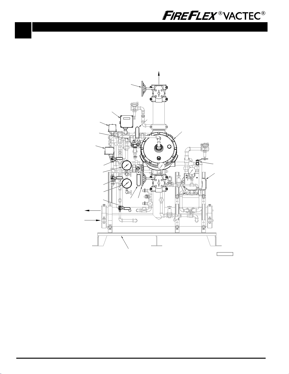
Figure 1 - Simplified system trim schematic
Typical dry-pipe vacuum sprinkler system with electric release (4" system shown)
FM-061H-0-254A
FIELD CONNECTION
TO OPEN DRAIN
(on both sides)
FIELD CONNECTION
TO WATER SUPPLY
(on both sides)
FIELD CONNECTION TO VACUUM
SPRINKLERS PIPING NETWORK
F
IRE
F
LEXd
VACTEC
d
System Base
(shown without enclosure)
D4
G1
A1
D3
G18
C1
G20
G10
B11
B12
B7
B5
B1 B6 D1
B10
Trim components:
A. Valve
A1 Deluge valve
B. Deluge valve trim
B1 Priming valve (N.O.)
B5 Alarm test valve (N.C.)
B6 Flow test valve (N.C.)
B7 Alarm line drain valve (N.C.)
B10 Manual emergency release valve (N.C.)
B11 Priming pressure water gauge & valve (N.O.)
B12 Water supply pressure gauge & valve (N.O.)
C. Water flow alarm trim
C1 Alarm pressure switch
D. Valves
D1 Water supply control valve (N.O.)
D3 Main drain valve (N.C.)
D4 Shut-off valve (N.O.)
G. Vacuum control
G1 Liquid ring vacuum pump
G10 System drain valve (N.C.)
G18 FLX-PC®VACUUM / PRESSURE CONTROLLER
Page 9 of 10
Integrated Fire Protection System B
Mechanical Section - Dry-pipe Vacuum Sprinkler System - Electric Release
FM-060M-0-112B
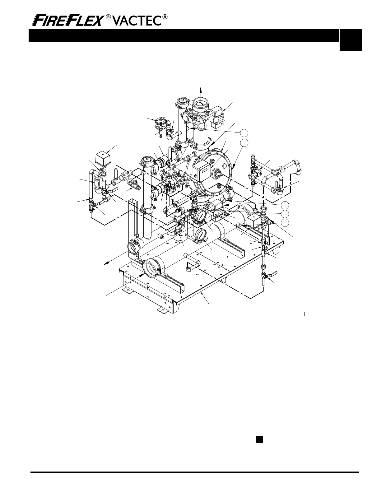
Figure 2 - Detailed system trim schematic
Typical dry-pipe vacuum sprinkler system with electric release (4" system shown)
G18
B7
B8
5
FM-061H-0-247A
FIELD CONNECTION
TO OPEN DRAIN
(on both sides)
FIELD CONNECTION
TO WATER SUPPLY
(on both sides)
D1
C1 D3
B6
B5
B9
B1
B2
B4
B3
B13
A1
B11
B12
B10
CONTRACTOR'S
HYDROSTATIC
TEST PORT
(water supply side)
FIELD CONNECTION TO VACUUM
SPRINKLERS PIPING NETWORK
B4
G20
F1
4
Towards Vacuum Supply
System Trim
3
1
Towards Vacuum Supply System Trim
2
CONTRACTOR'S HYDROSTATIC
TEST PORT (system side)
C2
G12
FIREFLEX VACTECSystem Base
(shown without enclosure)
D5
D4
G6
G8
Trim components:
A. Valve
A1 Deluge valve
B. Deluge valve trim
B1 Priming valve (N.O.)
B2 Strainer
B3 1/16" Restricted orifice
B4 Spring loaded check valve
B5 Alarm test valve (N.C.)
B6 Flow test valve (N.C.)
B7 Alarm line drain valve (N.C.)
B8 1/8" Restricted orifice
B9 PORV (pressure operated relief valve)
B10 Manual emergency release valve (N.C.)
B11 Priming pressure water gauge & valve (N.O.)
B12 Water supply pressure gauge & valve (N.O.)
B13 Clapper check valve
C. Water flow alarm trim
C1 Alarm pressure switch (PS10-1A)
C2 ¾"-NPT (20mm) connection to water motor gong
(strainer supplied by contractor)
D. Valves
D1 Water supply control valve (N.O.)
D3 Main drain valve (N.C.)
D4 Shut-off- valve (N.O.)
D5 Sight glass assembly
F. Release trim
F1 24VDC N.C. solenoid valve
G. Vacuum control
G6 Vacuum pump drain float check
G8 Vacuum pump network strainer
G10 See section D VACUUM SUPPLY
G12 Vacuum breaker valve
G18 FLX-PC® VACUUM / PRESSURE CONTROLLER
G20 Vacuum pump control pressure switch (PS40-1A)

Page 10 of 10
B
Integrated Fire Protection System
Mechanical Section - Dry-pipe Vacuum Sprinkler System - Electric Release
FM-060M-0-112B
This page is left intentionally blank.
Page 1 of 2
Integrated Fire Protection System
C
Trim Options - Vacuum Sprinkler System
FM-060M-0-88A
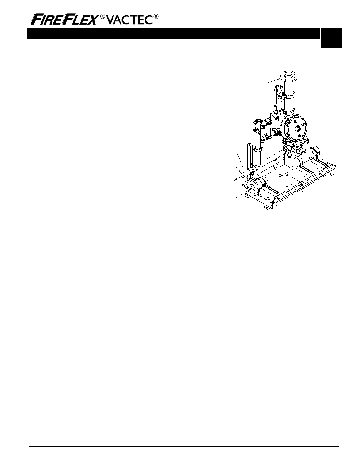
1. Semi-flange and full-flanged configuration
When required by the user, FIREFLEX®VACTEC®unit can
be provided in either a semi-flanged of full-flanged
configuration.
The semi-flanged option provides flanged fittings only on
the water inlet pipe (side needs to be specified at the time
of order) and on the system riser outlet. The drain
manifold is provided with a threaded end that also needs
to have its side specified (left or right). The rest of the
fittings are the same as usual with the main components
being provided in the standard flanged/grooved
configuration.
The full-flanged option is the same as above but goes a
step further with the main components being also provided
with a flanged/flanged configuration.
When provided, the face of the flanges will always be
located 6 inches (150mm) from the outside face of the
mounting base or cabinet surface.
Figure 1 - Semi-flanged configuration for vacuum
sprinkler system (shown without system trim)
Field Connection
to Water Supply
(specify side)
Flanged fitting
outside cabinet
(when provided)
FM-061H-0-225A
Flanged fitting outside cabinet
(when provided)
Threaded end
Field Connection
to Open Drain
(specify side)

Page 2 of 2
C
Integrated Fire Protection System
Trim Options - Vacuum Sprinkler System
FM-060M-0-88A
This page is left intentionally blank.
Page 1 of 2
Integrated Fire Protection System D
Vacuum Supply Section - Vacuum Sprinkler System - Electric Release
FM-060M-0-89C
1- Vacuum supply
Note: Numbers indicated between brackets refer to items
on the TRIM SCHEMATICS from this section and section B
MECHANICAL.
Vacuum sprinkler system uses negative vacuum pressure to
supervise the piping network. The vacuum supply is
provided within the FIREFLEX®VACTEC® unit. The vacuum
supply trim is factory assembled in the system cabinet,
calibrated and pressure tested.
The vacuum supply system trim includes a liquid ring
vacuum pump (G1), all regulating devices to control flow of
water and pump motor shut off electrical components.
The vacuum pump (G1) power requirement is specified at
220/240VAC, 50/60Hz, 1.5HP, 1phase.
The vacuum pump (G1) is able to establish the total required
vacuum pressure in 30 minutes for system capacity up to
4000 gallons.
1.1 Operation
The start and stop adjustments of the vacuum pump (G1)
are factory set and require no further adjustments. The
pump motor is controlled by a contactor (G17) which is
activated on and off by the FLX-PC® (G18) VACUUM /
PRESSURE CONTROLLER.
The liquid ring of the vacuum pump (G1) is generated by a
water line composed by a water ring control valve (G13), a
solenoid valve (G2), a pre-regulator (G3), a fine-adjust
regulator (G4) and a restricted orifice (G5). A float check
valve (G6) and a reversed check valve (G11) prevent flood
through possible water coming from drain collector.
Vacuum is sucked from the piping network through the
2-way check valve (G7). This check valve allows vacuum to
be sucked, but will prevent water to enter the vacuum
pump (G1) when deluge valve (A1) is opened.
When the piping network has been drained after operation,
the remaining water inside the deluge valve (A1) will be
drained out by the operation of the vacuum pump (G1).
To apply vacuum supply:
Switch ON the vacuum pump (G1) On/Off switch (G16).
To close vacuum supply:
Switch OFF the vacuum pump (G1) On/Off switch (G16).
1.2 Pressure settings
All pressure settings are factory set and do not need further
calibration unless malfunction.
a) FLX-PC® (G18) set to -140 mBAR (-14 kPa) for LOW
PRESSURE supervisory condition.
b) FLX-PC® (G18) set to -220 mBAR (-22 kPa) for HIGH
PRESSURE supervisory condition.
c) FLX-PC® (G18) set to -130 mBAR (-13 kPa) for ALARM
PRESSURE condition.
d) FLX-PC® (G18) set to -150 mBAR (-15 kPa) for vacuum
pump (G1) start.
e) FLX-PC® (G18) set to -180 mBAR (-18 kPa) for vacuum
pump (G1) stop.
f) Pre-regulator (G3) set to 50 PSI (344 kPa) via pre-
regulator pressure gauge (G14).
g) Fine-adjust regulator (G4) set to 10 PSI (69 kPa) via
fine-adjust regulator pressure gauge (G15).
h) Vacuum breaker valve (G9) set to -300 mBAR (-30 kPa)
i) Vacuum breaker valve (G12) set to -200 mBAR (-20 kPa)
1.3 Maintenance and inspection
If the vacuum pump (G1) is hard to start, too much water
could be present in the deluge valve (A1) system. To fix this
problem, close vacuum system and open system drain
valve (G10) until all water has been drained out. Close the
system drain valve and apply vacuum supply.
If the vacuum pump (G1) doesn't start at all, contactor (G17)
may have tripped. Open the junction box cover of the
vacuum pump controller and reset the contactor (refer to
section E CONTROLS). Reinstall the junction box cover.
The FLX-PC® (G18) VACUUM / PRESSURE CONTROLLER is
equipped with an hour counter which reveals the operating
time of the vacuum pump (G1). During regular maintenance,
verify the counter to see if the vacuum pump (G1) is
activated often. If so, this could point to an excessive leak in
the piping network.
The vacuum pump (G1) is fitted with "sealed for life" bearing
and should provide maintenance free life.
The vacuum pump (G1) is fitted with single acting
mechanical seals. These seals should be replaced when
worn, scratch or cracked. Replacement is also necessary
when rotating portion of the seal does not firmly grip the
shaft.
If the vacuum pump (G1) is to be out of service for extended
period of time, it should be internally protected from rusting
by using a suitable water soluble rust inhibitor, available from
Busch GVT. This will give protection for up to twelve (12)
months. Rotate the pump by hand to coat the interior of the
pump surfaces with the fluid. The pump should be revolved
periodically to prevent bearing indentation.
For more information, refer to Vacuum Pumps Dolphin
LX 0300-0430 A Installation and Operating Instructions.

Page 2 of 2
D
Integrated Fire Protection System
Vacuum Supply Section - Vacuum Sprinkler System - Electric Release
FM-060M-0-89C
Figure 1 – Detailed vacuum supply trim schematic
5
To System Trim
2
G10
FM-061H-0-218E
G8
G7
1
To Riser Trim
G8
G5
G15
G14
G4
G8
G6
G13
G3
G2
4
To Drain Trim
3
To Water Supply Trim
4
To Drain Trim
G9
G1
G11
Vacuum pump components:
G. Vacuum supply
G1 Liquid ring vacuum pump
G2 240VAC N.C. solenoid valve
G3 Pre-regulator
G4 Fine-adjust regulator
G5 0.125" restricted orifice
G6 Float check valve
G7 2-way check valve
G8 Strainer
G9 Vacuum breaker valve
G10 System drain valve (N.C.)
G11 Reversed check valve
G12 Refer to section B MECHANICAL
G13 Water ring cut-off valve (N.O.)
G14 Pre-regulator gauge & valve
G15 Fine-adjust regulator gauge & valve
G16 On/Off manual switch (see section E CONTROLS)
G17 Electric contactor (see section E CONTROLS)
G18 Refer to section B MECHANICAL
Table of contents


