CIC Torus 15 User manual
Installation Guide
For assistance, please email the manufacturer at
Diagram above is shown with optional reader attached.
Safety and Warnings
Notices
Contents
Please read this Installation Guide carefully. If the cabinet is sold, this guide must be provided to to the buyer and/or installers. Under no
circumstances does the manufacturer accept warranty or liability for damage caused by improper use or failing to follow these instructions.
This document contains information about products and services provided by CIC Technology. Every commercially reasonable effort has been taken to ensure the quality and accuracy of the
information provided, however the content is for informational purposes only. The described product or process in this document is subject to change without prior notice, due to continuous
development and improvement.
Neither CIC Technology nor any of its directors, employees or other representatives shall be responsible for any loss that you may incur, either directly or indirectly, arising from any use or
decisions based on the information provided.
Torus software, firmware, database, hardware, and mechanical design are subject to copyright owned by CIC Technology Pty Ltd. CIC Technology is the owner of all Torus and CIC trademarks
reproduced in this document. Other products, brands, trademarks referenced are not the property of CIC Technology.
POWER
Cabinet is an electronic device. It can be powered
using 110-240V AC power or Power Over Ethernet
(POE/POE+/POE++)
Safety & Warnings
Before You Begin
Package Contents
Installation Instructions
Adding a Card Reader or Other Device
Page 2
Page 3
Page 4
Page 5
Page 10
ENVIRONMENT
Cabinet is for interior use only. It must be installed
on a wall capable of supporting its weight, with no
direct exposure to sunlight or water.
TEMPERATURE
The operating temperature of the cabinets is
between 0°C and 55°C (32°F - 130°F).
CLEANING
Wipe the surface of the door and touchscreen
with a soft cloth. Use gentle cleaning solution or
water as ‘dry’ cleaning may cause dust particles to
scratch the surface. Never use abrasive or high
alkaline cleaners.
DAMAGE / SCRATCHING
Damage to the cabinet caused by intentional
misuse or failure to follow the instructions will not
be covered under warranty.
WEIGHT
Each cabinet is heavy (see page 4). Correct lifting
techniques and safe handling methods must be
observed.
OTHER
Torus is an Internet of Things (IoT) solution which
requires a subscription to the software and an
internet connection for the cabinet.
TORUS Installation Guide 2

Power
Before You Begin
AC Power
110-240V
OR
Power over Ethernet
POE / POE+ / POE++
The cabinet can be powered from a
regaular power outlet or by using
POE. Make sure the chosen option
is ready and available before
commencing installation.
The relevant ports should be within
2m / 6’ of the cabinet.
Provisioning key
The provisioning key is a 12-digit number found in the Torus
software. Each cabinet has a unique provisioning key that
must be entered into cabinet to complete the installation.
Provisioning Key
Fasteners are not supplied with the Torus cabinet. Each fastener
must hold at least 50lbs / 20kgs and be appropriate for the wall
substrate.
Mounting holes:
Fasteners
10mm
15mm
Tools Required
Power
Spirit Level with Magnetic Base
Ratchet Driver with 10mm Socket
10mm Open Ended Ring Wrench
Plus drill and tools for chosen fasteners.
Note: If a card reader is being installed, additional tools will be
required. Refer to card reader mounting instructions.
Connectivity
LAN
Local Area Network
OR
4G SIM Card
Regular - not micro or nano
The Torus Administrator has been
sent an activation email detailing
the requirements for each of these
methods. Cabinets must be
connected to the internet to
function.
TORUS Installation Guide 3

Package Contents
Keeping the cabinet upright at all times, cut the straps and lift
the outer box upwards.
Inside there will be a separate box containing cables and
accessories.
There are 4 sizes of Torus cabinet.
The installation process is largely the same for each size.
However, the Torus 100:
• attaches to the wall at 6 points instead of 4
• includes an additional strap to support the weight of the keypanel
• has 2 ribbon cables that connect to the Control Unit.
Accessories Box
Accessories
Override Key Backup Battery
12V 7AH
Screws & Washers
4 of each
Ethernet Cable
Cat5 Cable (5m)
Power Cable
Right Angle IEC Cable (5m)
Other
Key Rings & Accessories
Torus 15
77lbs / 35kgs
Torus 25
92lbs / 42kgs
Torus 50
119lbs / 54kgs
Torus 100
196lbs / 89kgs
Cabinet & Bracket
Torus Cabinet
Available in 4 sizes
Mounting Bracket
Connected but not secured
to the back of the cabinet
TORUS Installation Guide 4

Installing the Cabinet
Attach the mounting bracket to the wall
Prepare the cables so they can be retrieved
through the cable entry holes in the top right of
the mounting bracket.
Ensure that no cables are protruding as they will
inhibit the cabinet from attaching and result in
damaged cables.
Through the wall
behind the bracket
Into the mounting
bracket at any corner
External to the wall
Power and data cables that are on the outside
of the wall can enter the mounting bracket at
any of the four corners.
Through the wall cavity
Power and data cables that are run through the
wall can enter the cavity behind the bracket at
any point.
The mounting bracket is connected, but not
secured, to the back of the cabinet.
Gently and carefully tilt the cabinet forwards so
you can remove the bracket.
Cable Management
Height:
1600mm / 63”
from the floor.
Find the desired location on the wall and mark the holes ensuring the
bracket is level. Torus recommends that the top of the bracket is 1600mm /
63” from the floor so the screen will be at eye level, although any height can
be chosen based on the customer’s needs.
Torus 100 will attach to the wall at 6 locations, whereas the other cabinet
sizes will attach at 4 (each corner).
Using appropriate fasteners, secure the bracket to the wall.
Prepare Cables
TORUS Installation Guide 5
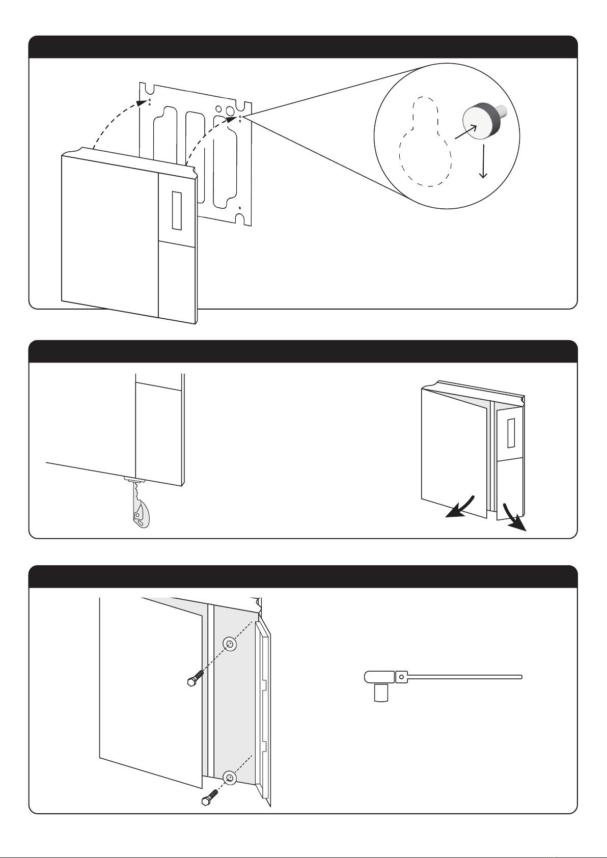
Hang the Cabinet on the Bracket
Use the Override Key to Open the Doors
Screw the Cabinet to the Bracket
Locate the override key and insert it
on the underside of the cabinet.
Turning the key will cause the doors
to pop open.
Open the right side door.
Use the screws and washers provided
to secure the cabinet to the bracket.
Lift the cabinet onto the mounting bracket
There are two pins at the top of the bracket that will locate into keyhole
slots in the back of the cabinet. Once both pins are inserted, the cabinet
will hang in place, supported by the bracket
The cabinets are very heavy - safe handling methods must be obvserved.
Override Key
Ratchet driver with 10mm socket
TORUS Installation Guide 6

Lower the Keypanel
Screw the Cabinet to the Bracket
Check Connections Reader
10mm Open Ended Ring Wrench/Spanner
Ratchet Driver with 10mm socket
Find the latch in the top of the right side of the cabinet.
Gently push it away from you to release the key panel.
Make sure the main door is open and lower the key panel.
Secure the cabinet to the bracket using the screws
and washers provided.
Access is limited around the top left screw so you
will need to use the opended spanner/wrench.
With the keypanel lowered, check that all of the boards are
seated correctly and the cables are firmly connected.
When complete, raise the keypanel until it locks in place.
The cabinet is capable of
accepting the input from a
reader using OSDP or Wiegand.
If you are installing a reader, skip
to supplementary instructions on
page 10.
TORUS Installation Guide 7

Bring in the Cables
Check all Connections
Connect Power and Backup Battery
Now that the cabinet is secured to the
wall, you can bring the network cable (and
power if not using POE) into the cabinet.
Follow this diagram and make sure all of
the cabling is plugged in securely to the
back of the control unit.
KSP Ribbon Cable/s
These ports are interchangeable
Torus 100 will have 2 cables
Power cable
Green Phoenix connector
Ground
This may be on the other side.
Ethernet
Door Solenoid Door Sensor
If you are not using POE, connect the power cable to the PSU
Retrieve the backup battery from the accessories box and insert
it beneath the PSU. Attach the red wire to the postive terminal
and the black wire to the negative terminal.
Secure battery in place with velcro strap.
TORUS Installation Guide 8

Startup the Cabinet
Close both doors.
Tap the screen to
boot up the cabinet.
Enter Provisioning Key
End-points
Ports
IP Address
Provisioning Key
The cabinet will show you if the
necessary network configurations
have been made. If not, you will be
unable to progress to the next step.
Enter the provisioning key.
A secure connection will be made
between the cabinet and the
customer’s software account.
Congratulations on completing the cabinet installation.
Thank you for being Torus partner, connect with us here:
torus-technology.com
linkedin.com/company/torus-technology
TORUS Installation Guide 9

Remove Door
Unplug Cables
Open Right Hand Door
Installing a Reader
User ID
PIN
Login
Settings
Shutdown
Reader
Make sure you are supporting the
weight of the door
Remove the hinge pins from both the upper
and lower hinge.
This will separate the door from the cabinet.
Gently lay the door face down on a
non-abrasive surface so as not to scratch
the touchscreen.
Be careful of the 4G modem, which
protrudes from the control unit.
Use the override key
to open the
right hand door.
If the cabinet is already in a powered-on state,
make sure you gracefully shut it down first.
1. Login as a cabinet admin,
2. Tap settings,
3. Tap shutdown.
Wait for the screen to turn completely black.
KSP Ribbon Cable/s
These 2 ports are
interchangeable
Torus 100 will have 2 cables
Power cable
Green Phoenix connector
Ground
This may be on
the other side
Ethernet
Door Solenoid Door Sensor
The reader will be
mounted on the panel
below the screen.
Unlplug these cables from
the back of the control unit
so you can remove the door.
TORUS Installation Guide 10

Drill Holes
Keep the control unit face down on a
non-abrasive surface.
Take special care not to scratch the
touch screen.
Mark the center point of the lower
panel and drill the holes required for
the chosen reader/device.
Remove any shavings or burrs to
allow for a flush mounting.
Attach Reader
Feed the cables of the reader
through the hole and secure the
reader to the panel beneath the
screen.
While handling the control unit, be
careful of the 4G modem.
Wire the Reader
OSDP (RS485)
The cabinet is capable of accepting
inputs from Wiegand or OSDP devices.
Every reader is different, so follow the
manufacturer’s instructions and connect
it to the appropriate point on the
control unit.
Reattach Control Unit
Connect the control unit back to the
cabinet by inserting the pins into the
hinges.
Plug all of the other cables back in
following the diagram on the previous
page.
Close the cabinet door.
Use 8 pins, 2 rows, 2.54mm pitch.
TE Connectivity, AMPMODU MOD II Female
RS485_CONN
GND
5V
A
B
GND
12V
B
A
Wiegand
Rear of Control Unit Panel
Use 5 pin, 3.81mm pitch
Wurth Elektronik 361 Pluggable Terminal Block
CARD_BIO1
D1
D0
GND
+5V
+12V
TORUS Installation Guide 11
This manual suits for next models
3
Table of contents


