2
1.4. Safety Instructions for Operators
Safety instructions for the proper use of this product must
be followed. This information must be available at all
times to personnel responsible for installation, operation,
maintenance and inspection of this product. Adequate
steps must be taken to prevent the occurrence of hazar-
dous conditions that can be caused by electric energy
and the convertible energy of the process media. Such
conditions can, for example, be the result of improper
electrical or process connections. Detailed information is
available in relevant published norms (DIN EN, UVW in
Germany; and equivalents in other countries), industrial
standards such as DVWG, Ex-, GL-, VDE guidelines, as
well as regulations of the local authorities (e.g., EVUs in
Germany).
1.5. Modifications Forbidden
Modification or other technical alteration of the product is
not permissible. This also applies to the use of unautho-
rized spare parts for repair / maintenance of the product.
Any modifications to this product, if and as necessary,
should be done only by Fischer Mess- und Regeltechnik
GmbH.
1.6. Operational Restrictions
The operational reliability of the product is guaranteed
only when used for intended purposes. The product must
be selected and configured for use specifically with defi-
ned process media. The limiting values of operating pa-
rameters, as given in the product specification sheet,
must never be crossed.
1.7. Safety Considerations during Installation and
Maintenance
The safety instructions given in this manual, existing na-
tional regulations relating to accident prevention and the
internal safety rules and procedures of the user organi-
zation regarding safety during installation, operation and
servicing must all be followed meticulously.
It is the responsibility of the users to ensure that only sui-
tably qualified and experienced technical personnel are
used for installation, operation and servicing of this
equipment.
2. Intended Applications
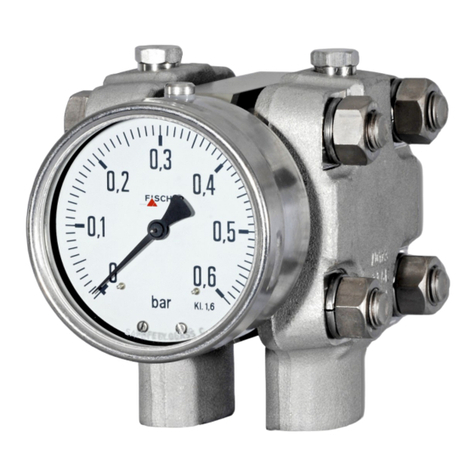
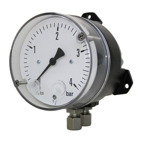
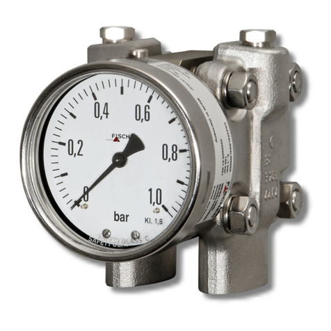
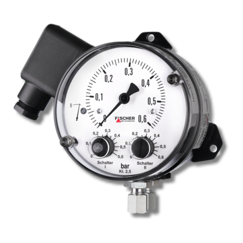
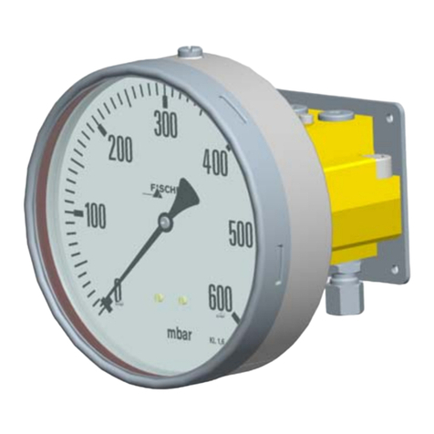
The DA01 is used for indication and switching differential
pressure of gaseous and liquid media. The product must
be used only for applications and under conditions spe-
cified by the manufacturer.
3. Product Description and Functions
3.1. Schematic Diagram
3.2. Principles of Operation
The pressures to be compared act on flexible stainless
steel diaphragms on either side of the sensing capsule.
The two diaphragms are mechanically linked by a rigid
connecting rod. To compensate high static pressures,
the cavity between the two diaphragms is filled with hy-
draulic fluid. When pressures are equal on both dia-
phragms, they are at zero position. When there is a
difference in pressures acting on the two diaphragms,
they are deflected away from the high pressure side, to-
wards the lower pressure side, causing a displacement
of the connecting rod. A precision mechanism translates
the linear displacement of the diaphragm connecting rod
to angular movement of the gauge's dial pointer. The
pointer's displacement range of 270° corresponds to the
full scale differential pressure.
The connecting rod has intermediate flanges on either si-
de, which protects the diaphragms against excess diffe-
rential pressure. When differential pressure exceeds the
specified limit, the flange towards the lower pressure side
is pressed against the sealing O-ring on the inside of the
sensing capsule. This action isolates the fluid adjacent to
the diaphragm exposed to lower pressure, from the fluid
at higher pressure on the other side. This limits the pres-
sure differential across the lower pressure diaphragm,
and equalizes the pressure across the higher pressure
diaphragm. Thus both diaphragms are protected against
excess deflection and risks of rupturing.
1 Connecting rod
2 O-ring, differential over-
pressure protection
3 Sensing diaphragm
4 Pointer mechanism
5 Lever
6 Link
7 Pressure transfer liquid


