manuals.online logo
Brands
  1. Home
  2. •
  3. Brands
  4. •
  5. Dungs
  6. •
  7. Switch
  8. •
  9. Dungs CPI 400 User manual

Dungs CPI 400 User manual

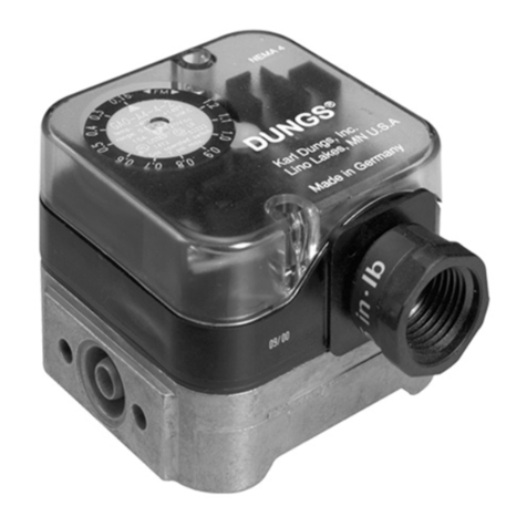
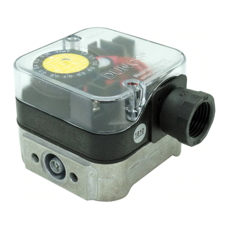
Closed position indicator CPI 400 visually and electrically indicates when the valve is either in the closed or open position.
Mounts directly to the DMV, SV, and MVD series valves. When the valve is closed a orange light is visible, when the valve
is open a green light is visible.
Gases
Natural gas, propane, butane, noncorrosive gases,
and air. Suitable for up to 0.1% by volume, dry H2S when
used with nickel plated brass adatper.
Switch Type
SPDT
Switch Action
Valve open: Green light
Valve closed: Orange light
Contact Rating
10 A res, 8 FLA, 48 LRA @120 Vac. 1A max @ 24Vdc and
1A max @ 12Vdc. When used, the 24Vdc/Vac indicator
light consumes 20mA when enegized.
Enclosure
NEMA Type 4
CPI 400 Valve Switch and Position Indicator
Installation Manual
SPECIFICATIONS
Mounting
• The valve must be de-energized and the gas supply shut
off before mounting the CPI.
• Disconnect all power to the switch before beginning to
prevent electrical shock and equipment damage.
Mounting Procedure (reference Fig. 1 above)
• IMPORTANT!! Before mounting the brass adapter
to the valve or to the CPI 400, use your fingers to
verify that the pin slides freely inside the brass
adapter. If this pin does not slide freely, apply a
large enough force to the appropriate side to free
the pin.
• Using a 5mm hex wrench, remove the plug and its o-ring
located at the bottom of the valve.
• Verify that the brass adapter has a clean o-ring and its
threads and the groove into which the brass adapter
mounts, are clean and in good condition.
CPI 400 Installation Manual - P/N 80114 - Ed. 01/09
• Mount the brass adapter into the valve.
• Use a 9/16” (14 mm) open end wrench and torque to 44
in-lbs (5Nm), which is about 1/4 turn (after nger tight).
DO NOT overtighten.
• Mount the CPI switch onto the brass adapter. Push the
CPI housing towards the valve until it stops.
• Turn/Position the CPI so that the wiring and conduit con-
nection apply the least amount of torque as possible.
• Tighten the set screw so that the CPI housing is secured
to the brass adapter.
• Do not turn the CPI 400 after tightening the set screw;
this may strip the brass adapter. The brass adapter could
loosen and the assembly may leak.
• Perform a leak test to verify that no leakage occurs around
the o-ring.
MOUNTING
ATTENTION
Fig. 1
• Read these instructions carefully.
• Failure to follow them and/or improper installation may
cause explosion, property damage and injuries.
• Installation must be done with the supervision of a
licensed burner technician.
• Check the ratings in the specications to make sure that
they are suitable for your application.
• Never perform work if gas pressure or power is applied,
or in the presence of an open flame.
• Once installed, perform a complete checkout including
leak testing.
• Verify proper operation after servicing.
• The system must be installed, used, and maintaned to
meet all applicable national and local code requirements
such as but not limited to NFPA 86, CSD-1, ANSI Z21.13,
UL 795, NFPA 85, or CSA B149.3.
1 … 2
Karl Dungs, Inc
524 Apollo Drive, Suite 10 Lino Lakes, MN 55014 U.S.A.
Phone: (651) 792-8912 Fax: (651) 792-8919 E-mail: [email protected]
Power Equipment Company
2011 Williamsburg Road Richmond, VA 23231 USA
Phone: 804.236.3800 Fax: 804.236.3882 E-Mail: [email protected]
N
L1
Required Wiring:
• Do not exceed the switches electrical ratings.
• Use 14 or 16 gauge wire for at least 75˚C (167˚F).
• For NEMA 4 applications, NEMA 4 conduit or wiring
methods must be used.
• Run one wire (the COMMON) to the L1 terminal, one
to the GROUND terminal, one from the terminal 2
“Proof Terminal” to the Proof of Closure terminal of the
Flame Safeguard, and one (the NEUTRAL) to L2 on
the CPI 400.
NOTE: If equipment neutral is not wired to L2 on the
CPI 400, the lights will not properly indicate the valve
position. The ORANGE light should be on when the
valve is closed, The GREEN light should be on when
the valve is open (FM and NPFA 86 requirement).
The CPI 400 must be calibrated to the specic valve it is
used on. Failing to properly calibrate this switch may lead
to nuisance problems or to an unsafe startup condition.
Calibrating the CPI: (Reference Fig. 2)
The CPI must be properly mounted to the valve, and•
the valve must be closed.
Disconnect all power to the CPI 400 before adjusting to•
prevent electrical shock and equipment damage.
Remove clear cover.•
Turn the adjustment dial counterclockwise until it stops.•
Then turn the adjustment dial clockwise until the switch•
makes. If there is too much noise to hear the switch
trip, proceed to Calibrating the CPI in noisy environ-
ments.
Note the position of the set point in reference to the•
white lines on the scale.
Turn the adjustment dial• two additional increments
clockwise to the same relative position.
Replace clear cover, the CPI is now adjusted.•
Calibrating the CPI in noisy environments:
Verify that there are no stray wires that are potentially a•
shock hazard while the dial is being manually adjusted.
Calibration and Testing
Fig. 3
Fig. 2
Apply 120Vac to terminals L1 and L2 of the CPI.•
Turn the adjustment dial counterclockwise until it stops.•
The GREEN light should be illuminated.
Then turn the adjustment dial clockwise until the RED•
light illuminates.
Note the position of the set point in reference to the•
white lines on the scale.
Turn the adjustment dial• two additional increments
clock-wise to the same relative position.
Replace clear cover, and the CPI is now ready for•
serivce.
Annual Testing
Perform a switch continuity test at least annually to verify•
that with the valves de-engerzied, the continuity between
the switch contacts T3 (COM) and T2 (Proof Terminal)
does not exceed 5 ohms, and verify that there is no con-
tinuity between the switch contacts T3 (COM) and T1.
Then, energize the valve, and verify that the continuity•
between the switch contacts T3 (COM) and T1 does not
exceed 5 ohms, and then verify that there is no continuity
between the switch contacts T3 (COM) and T2.
If any above check fails, do not use the CPI and contact•
DUNGS immediately.
Wiring
Replacement Parts
Clear plastic cover
120Vac neon lights (one orange and one green)
24Vdc neon lights (one red and one green)
1/2”NPT conduit adapter (PG 11)
240-837
229-338
248-183
220-566
Brass adapter (standard)
Brass adapter (Ni plated)
224-417
224-417B
Do not wire this switch to close a circuit that
will directly power another safety shutoff
valve. Doing so could result in a safety valve
being energized and opened rather than remain-
ing closed.
2 … 2

Other Dungs Switch manuals

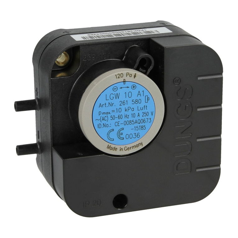
Dungs GW A6 Series Service manual

Dungs

Dungs GW A6 Series Service manual

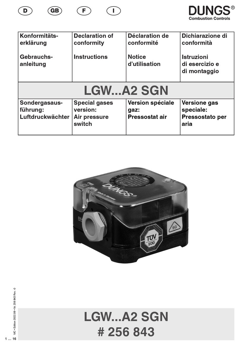
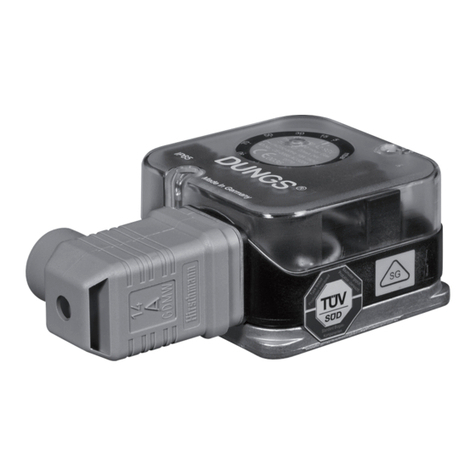
Dungs LGW A2 SGN Series User manual

Dungs

Dungs LGW A2 SGN Series User manual

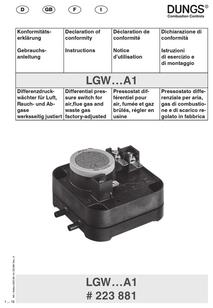
Dungs LGW A1 Series Service manual

Dungs

Dungs LGW A1 Series Service manual

Dungs LGW A2 SGN Series User manual

Dungs

Dungs LGW A2 SGN Series User manual

Dungs LGW A2 Series User manual

Dungs

Dungs LGW A2 Series User manual

Dungs LGW A1 Series User manual

Dungs

Dungs LGW A1 Series User manual

Dungs AA-A1-0 Series User manual

Dungs

Dungs AA-A1-0 Series User manual

Dungs GW A4/2 HP X Series User manual

Dungs

Dungs GW A4/2 HP X Series User manual

Dungs LGW A2 Series Service manual

Dungs

Dungs LGW A2 Series Service manual

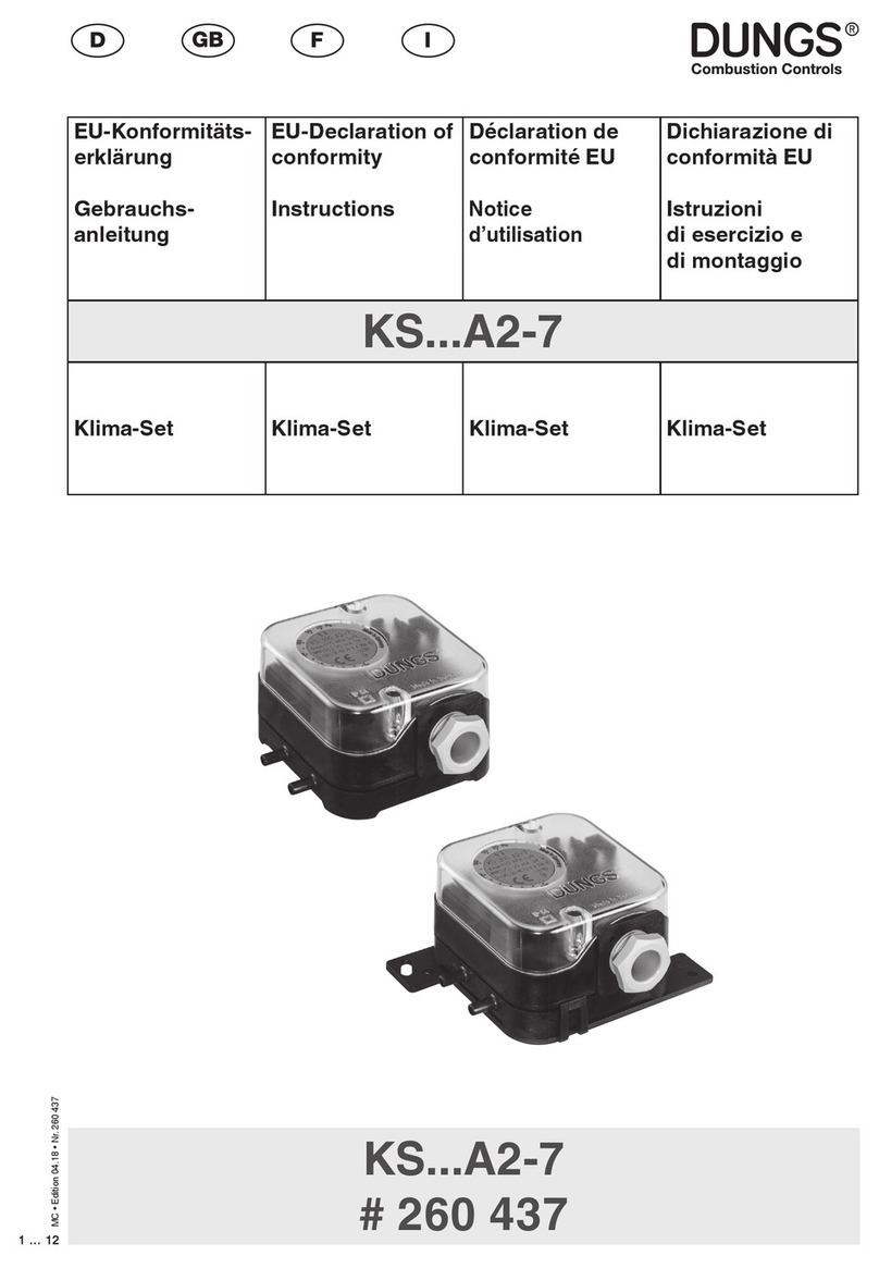
Dungs KS A2-7 Series User manual

Dungs

Dungs KS A2-7 Series User manual

Dungs LGW A2 Series Service manual

Dungs

Dungs LGW A2 Series Service manual

Dungs GGW A4/2 X Series User manual

Dungs

Dungs GGW A4/2 X Series User manual

Dungs Klima-Set KS***A2-7 Series Service manual

Dungs

Dungs Klima-Set KS***A2-7 Series Service manual

Dungs LGW A4 SGV Series User manual

Dungs

Dungs LGW A4 SGV Series User manual

Dungs GAO-A2 Series User manual

Dungs

Dungs GAO-A2 Series User manual

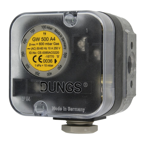
Dungs GW   500 A4/2 HP X Service manual

Dungs

Dungs GW 500 A4/2 HP X Service manual

Dungs GW A4 Series User manual

Dungs

Dungs GW A4 Series User manual

Dungs GW A2 Series User manual

Dungs

Dungs GW A2 Series User manual

Dungs GW A4 Series User manual

Dungs

Dungs GW A4 Series User manual

Dungs GW A4 Series User manual

Dungs

Dungs GW A4 Series User manual

Dungs LGW A2 Series Service manual

Dungs

Dungs LGW A2 Series Service manual

Dungs LGW A1 Series Service manual

Dungs

Dungs LGW A1 Series Service manual

Dungs GGW A4/2 X Series User manual

Dungs

Dungs GGW A4/2 X Series User manual

Dungs GGAO-A4-4 User manual

Dungs

Dungs GGAO-A4-4 User manual

Popular Switch manuals by other brands

steute RF 10 SW868 Mounting and wiring instructions

steute

steute RF 10 SW868 Mounting and wiring instructions

Optoma PS200T user manual

Optoma

Optoma PS200T user manual

Sony PVS-R102 Service manual

Sony

Sony PVS-R102 Service manual

TP-Link tapo S505D user guide

TP-Link

TP-Link tapo S505D user guide

Dell Networking N2000 Series Firmware upgrade

Dell Networking

Dell Networking N2000 Series Firmware upgrade

Allied Telesis AT-x230-10GP installation guide

Allied Telesis

Allied Telesis AT-x230-10GP installation guide

HP A7533A - Brocade 4Gb SAN Switch Base Administrator's guide

HP

HP A7533A - Brocade 4Gb SAN Switch Base Administrator's guide

Brocade Communications Systems A7990A - StorageWorks SAN Director 4/16 Blade... Reference

Brocade Communications Systems

Brocade Communications Systems A7990A - StorageWorks SAN Director 4/16 Blade... Reference

Televes 769146 quick start guide

Televes

Televes 769146 quick start guide

Cooper Kyle NR Series Maintenance instructions

Cooper

Cooper Kyle NR Series Maintenance instructions

G&D CATCenter NEO16 installation guide

G&D

G&D CATCenter NEO16 installation guide

Hama 75122224 operating instructions

Hama

Hama 75122224 operating instructions

Juniper QFX10002 Hardware guide

Juniper

Juniper QFX10002 Hardware guide

Extreme Networks Summit X150 Series Hardware installation guide

Extreme Networks

Extreme Networks Summit X150 Series Hardware installation guide

HP ProCurve 2610-48 specification

HP

HP ProCurve 2610-48 specification

Amphenol RESMLAC 28 MG installation guide

Amphenol

Amphenol RESMLAC 28 MG installation guide

H3C S7504E-XS Installation, quick start

H3C

H3C S7504E-XS Installation, quick start

NETGEAR ProSafe XS712T installation guide

NETGEAR

NETGEAR ProSafe XS712T installation guide

manuals.online logo
manuals.online logoBrands
  • About & Mission
  • Contact us
  • Privacy Policy
  • Terms and Conditions

Copyright 2025 Manuals.Online. All Rights Reserved.