Fisher & Paykel RS6121VL2K1 User manual

INTEGRATED COLUMNS
WINE CABINET
RS6121VL2K1 & RS6121VR2K1
models
INSTALLATION GUIDE
NZ AU GB IE SG HK
86021A11.19


3
CONTENTS
IMPORTANT!
SAVE THESE INSTRUCTIONS
The models shown in this installation guide may not be available in all markets and are subject to change at any time. For current details about model and specification availability in your country,
go to our website fisherpaykel.com or contact your local Fisher & Paykel dealer.
SAFETY AND WARNINGS 4
INTEGRATED COLUMNS — WINE CABINET 5
COMPONENTS 6
DOOR PANEL AND HANDLE SETS 8
WINE DISPLAY ACCESSORIES 9
TOOLS 9
APPLIANCE DIMENSIONS 10
CAVITY DIMENSIONS 11
DOOR PANEL DIMENSIONS 13
TOE KICK PANEL DIMENSIONS 14
CUSTOM DOOR PANEL DIMENSIONS 15
DOOR CLEARANCE 16
ELECTRICAL DIMENSIONS 17
ELECTRICAL SPECIFICATIONS 18
BEFORE INSTALLATION 19
Check your appliance 19
Move your appliance 19
Check the installation location 20
INSTALL ANTI-TIP BRACKET 21
CONNECT TO POWER SUPPLY 22
ATTACH DEPTH ALIGNMENT GAUGES 23
POSITION APPLIANCE INSIDE THE CABINETRY 24
Attach barbed plugs 24
ALIGN APPLIANCE INSIDE THE CABINETRY 25
Align depth gauges with cabinetry 25
Adjusting appliance inside the cabinetry 26
FIX APPLIANCE INSIDE THE CABINETRY 27
INSTALL CARBON FILTER 28
PREPARE FOR DOOR PANEL INSTALLATION 29
Removing hanging bracket 29
Attaching door handle 30
Attaching hanging bracket and side brackets 30
Attaching long glass trims 31
Attaching short glass trims 32
INSTALL DOOR PANEL 33
Hanging door panel 33
Adjusting door panel 34
INSTALL TOE KICK MOUNTING PLATE 35
Adjusting toe kick grille 35
Installing toe kick mounting plate 35
INSTALL TOE KICK AND GRILLES 36
Installing toe kick 36
Attaching top and bottom grilles 36
INSTALL CABINET TRIMS 37
Re-installing top trim 37
Re-installing flow divider 37
Installing side trims 38
INSTALL DOOR TRIMS 39
WINE DISPLAY 40
OPTIONAL—CHANGE DOOR HINGES 41
Removing the door 41
Removing top door hinge 42
Removing bottom door hinge 42
Moving the sensor housing 43
Top hinge installation 44
Bottom hinge installation 44
Door brackets 45
Door installation 46
FINAL CHECKLIST 47

4
!WARNING!
Electric Shock Hazard
Read and follow the safety and warnings
outlined in this installation guide before
operating this appliance.
Failure to do so can result in death, electric
shock, fire or injury topersons.
!WARNING!
Cut Hazard
Take care—panel edges are sharp.
Failure to use caution could result in injury
or cuts.
!WARNING!
This appliance is top-heavy and must
be secured to prevent the possibility of
tippingforward.
To ensure that the appliance is stable under
all loading conditions, theanti-tip bracket
and fittings supplied must be installed
according tothe following installation steps
by a professional installer.
SAFETY AND WARNINGS
IMPORTANT SAFETY INSTRUCTIONS
BEFORE INSTALLATION
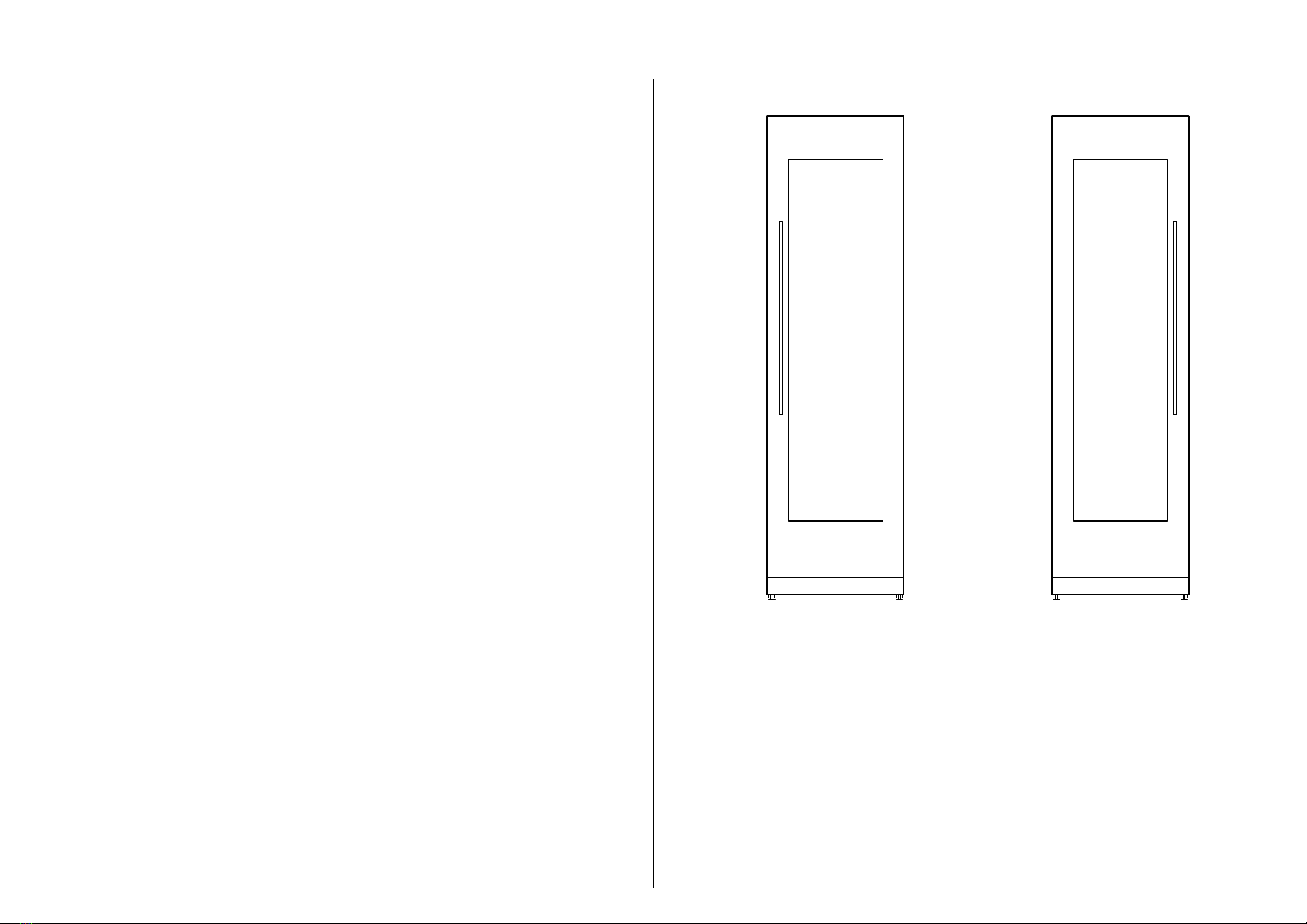
zThe appliance has front and rear rollers for moving the appliance forward and backward.
Do not move the appliance sideways to avoid damaging the rollers or the floor
covering/surface.
zEnsure your appliance is not exposed to any heat generating appliance eg cooktop,
oven or dishwasher.
zThe appliance must be installed by a qualified installer, or Fisher & Paykel trained and
supported service technician to avoid faulty electrical connection.
zAll connections for electrical power and earthing must comply with local codes and
ordinances and be made by licensed personnel when required.
zAvoid installation of the appliance/s under a ground fault circuit interrupter (GFCI).
zEnsure the appliance is installed properly. Improper installation that results in appliance
failure is not covered under the appliance warranty.
UNPACKING
zThe appliance is heavy (including packaging — 302lb/137kg) and requires at least
twopersons to move and install. Avoid scratching the surface of your appliance when
moving or installing.
zKeep the appliance stable and door closed to prevent tipping over when moving to
installation location.
zEnsure feet of the appliance are retracted before moving to installation location.
zIf appliance is damaged, contact your Fisher & Paykel dealer.
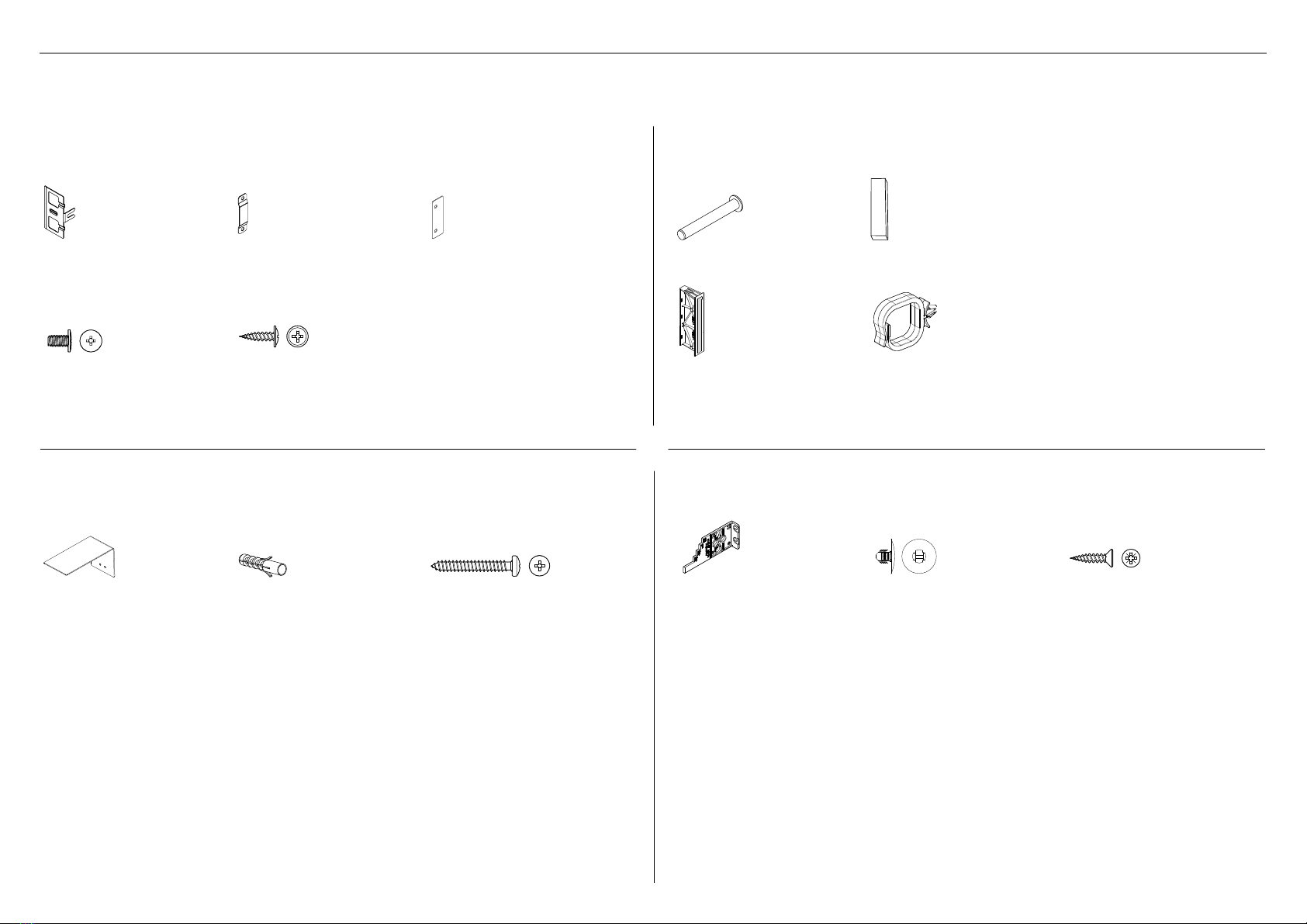
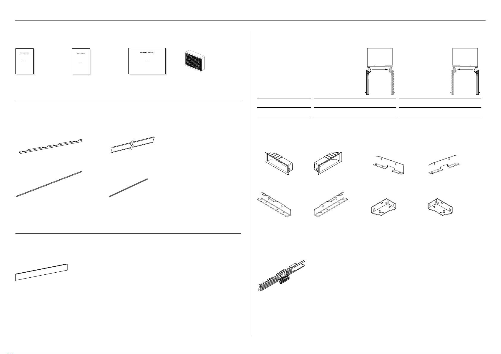
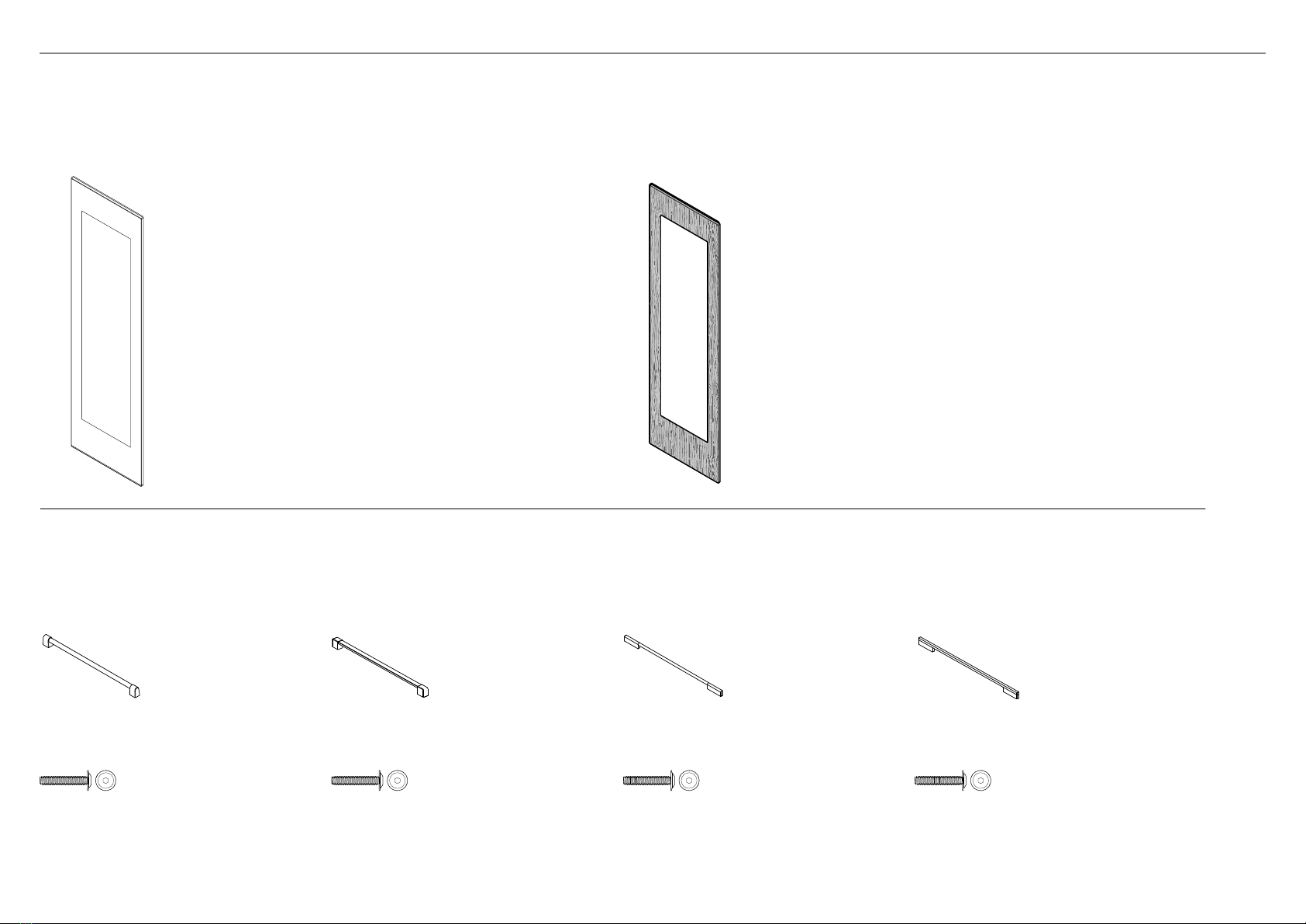
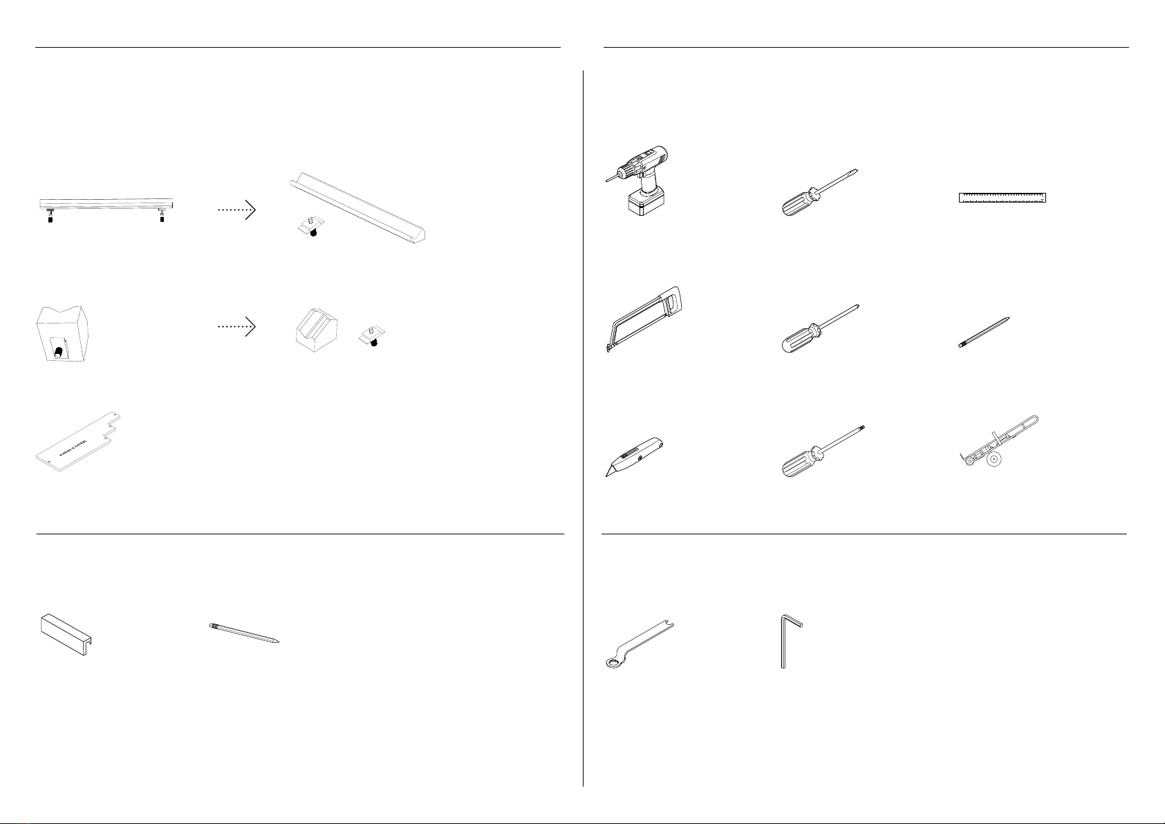
zCheck all components and accessories are complete. Refer to 'Components' page.
zRecord the model and registration numbers for future servicing or repair of
your appliance.
ELECTRICAL
zElectrical connection for these appliances must be located in an adjacent area or unit
(cabinet or cupboard) that is easily accessible in case of repair or disconnection.
zOnce installed, the service technician will NOT remove the appliance from the cavity to
gain access for repair.
WARNING!
zElectric shock hazard! Assume all parts live.
zDisconnect supply before servicing and installation.

5
SAFETY AND WARNINGS INTEGRATED COLUMNS — WINE CABINET
INSTALLATION
Cavity preparation
zThe anti-tip bracket and fittings supplied must be fitted tothe wall of the finished
enclosure to withstand a 225lb/100kg load.
zEnsure that the anti-tip bracket is installed correctly to prevent the possibility of the
appliance tipping forward when the door is open.
Positioning inside the cabinetry
zDO NOT attempt to open the door until the appliance is fully installed.
zEnsure the door of the appliance is closed when rolling into thecabinetry.
zEnsure the power cord is not run over or damaged when rolling the product
into the cabinetry.
Aligning inside the cabinetry
zEnsure the doors are in line with the cabinetry front and the appliance iscentred.
zAll four corners of the appliance must be supported firmly onto the floor to eliminate any
movement. Installing the appliance on a soft, uneven, or not level floor may cause twisting
and poor door sealing.
Fixing inside the cabinetry
zUse low speed, low torque setting when using a powered driver for the screws when fixing
or aligning the product.
zMake sure to remove the depth alignment brackets before fixing theappliance inside
the cabinetry.
zOpen the appliance door to remove the alignment brackets from both sides of the
appliance, and then re-tighten the screws.
Door panel installation
Stainless steel
zProtect the finish of the Fisher & Paykel Stainless Steel door panels from any
scratch or damage.
zLeave the protective film on the panels when hanging and remove the film only when the
installation is complete.
Custom
zIf using Custom door panels, ensure they are prepared as per 'Custom door panel
dimensions' section.
zEnsure the screw pilot holes do not penetrate the full depth of the panel.
zDo not place the handle holes in marked areas to avoid clashing with panel
attachment brackets.
zMinimum panel thickness where screw hole is drilled must be 16mm.
Door hinge change
zDoor hinges are interchangeable for each model. A hinge change kit is available
and can be purchased separately if you prefer to change from ‘right hand hinge’ to
‘left hand hinge’ or vise versa.
RS6121VL2K1
RS6121VR2K1

6
Installation kit (Internal box)
Supplied with appliance
Door panel attachmentkit
Side bracket
(6)
Bracket slider
(6)
Side spacer bracket
(6)
M5 x 14
Mush Head
SS
Philips Screw
M5 x 14
Mush Head
SS
Philips Screw
#8 x 16
Mush Washer
Twin Thread
Philips Screw
#8 x 16
Mush Washer
Twin Thread
Philips Screw
For SS door panels:
8Gx16 Mush washer screw (30)
For Custom door panels:
M5x12 Cross-head screw (30)
Install fasteners kit
#8 x 19
Countersunk
Twin Thread
Posi Screw
#8 x 19
Countersunk
Twin Thread
Posi Screw
Depth alignment gauge
(4)
Barbed plug
(2)
8Gx16 Countersunk screw
(7)
Anti-tip bracket assemblykit
#10x40
Pan Head
Philips Screw
#10x40
Pan Head
Philips Screw
Anti-tip bracket
(1)
Masonry plug
(4)
10-12x35mm cross-head screw
(5)
Miscellaneous components
Hinge limiting pin
(3)
Air toe kick seal
(1)
Flow divider cap
(1)
Locking clip
(2)
COMPONENTS

7
Miscellaneous items (MI) pack
Supplied with appliance
USER GUIDE
US CA NZ AU GB IE SG HK
863023A 09.19
INTEGRATED COLUMN
WINE CABINET
RS2484VL2K1, RS2484VR2K1,
RS6121VL2K1, RS6121VR2K1
models
SERVICE & WARRANTY
SERVICE ET GARANTIE
ΣΈΡΒΙΣΚΑΙ ΕΓΓΎΗΣΗ
SERVIZIO E GARANZIA
SERVICE & GARANTIE
HUOLTO JA TAKUU
SERVICE OG GARANTI
保修和维修
服務和保修
INTEGRATED COLUMNS
WINE CABINET
RS2484VL2K1, RS2484VR2K1,
RS6121VL2K1, RS6121VR2K1
models
INSTALLATION GUIDE
US CA NZ AU GB IE SG HK
863020A 09.19
User guide
(1)
Service & Warranty
(1)
Installation guide
(1)
Air carbon filters
#862755
(2)
Install parts (External box)
Supplied with appliance
Door panel side extrusion
(2)
Cabinet side trim assembly
(1)
Long glass trim (2) Short glass trim (2)
Toe kick install kit
Not supplied and must be purchased separately
Toe kick
(1)
●●Standard toe kick height is 102mm forstandard stainless steel door panel.
●●For Custom door panel installation, atoe kick 2" – 6" (50-152mm) must be fitted
andadjusted accordingly.
●●An extra bottom grille is required for a2" (50mm) toe kick installation. You can purchase
the extra bottom grille (Part No. 847542P) online at fisherpaykel.com.
Top grille assembly
Top (fixed) grille
(1)
Hinge change kit (Optional)
Not supplied and must be purchased separately
MODEL LEFT HINGE TO RIGHT HINGE RIGHT HINGE TO LEFT HINGE
RS61 848188 848187
Each kit includes: Hinge change assembly (1x), Top (fixed) grille assembly (1x)
Hinge change assembly
Hinge top
pocket RH (2)
Hinge top
pocket LH (2)
K05 top adaptor
bracket RH (1)
K05 top adaptor
bracket LH (1)
Bottom adaptor
bracket RH (1)
Bottom adaptor
bracket LH (1)
Bottom hinge
bracket RH(1)
Bottom hinge
bracket LH (1)
COMPONENTS

8
Door panel set
Not supplied and must be purchased separately
Stainless steel door panel set:
(Fisher & Paykel)
Custom door panel set:
Supplied by customers to match their cabinetry.
Custom Door Panel must leave glass pane visible.
A full custom panel sheathing over the glass pane
does not meet the specifications of this appliance.
Door handle set
Not supplied and must be purchased separately. Select between the options below:
Professional round
handle kit (CA:24980)
Professional square
handle kit (CA:24982)
Contemporary round
handle kit (CA:24981)
Contemporary square
handle kit (CA:24979)
Professional round
door handle (1)
Professional square
door handle (1)
Contemporary round
door handle (1)
Contemporary square
door handle (1)
M5 x 25
Pan Head
Socket Screw
OR
M5x25 hex screw
M5 x 25
Pan Head
Socket Screw
OR
M5x25 hex screw
M5 x 25
Pan Head
Socket Screw
OR
M5x25 hex screw
M5 x 25
Pan Head
Socket Screw
OR
M5x25 hex screw
M5 x 25
Pan Head
Socket Screw
OR
M5x25 hex screw
M5 x 25
Pan Head
Socket Screw
OR
M5x25 hex screw
M5 x 25
Pan Head
Socket Screw
OR
M5x25 hex screw
M5 x 25
Pan Head
Socket Screw
OR
M5x25 hex screw
M5x25 Hex screw
(4)
M5x25 Hex screw
(4)
M5x25 Hex screw
(4)
M5x25 Hex screw
(4)
DOOR PANEL AND HANDLE SETS

9
TOOLSWINE DISPLAY ACCESSORIES
2x 1x
Handle assembly (1)
Cradle assembly (4)
Spacer (1)
Required tools
Not supplied
Powered driver Flathead screwdriver Ruler
Hacksaw Cross-head screwdriver Pencil
Cutter T2 star-head screwdriver Hand truck
Supplied tools
Included in installation kit
Spanner 13mm
(1)
Hex key
(1)
IMPORTANT!
Wine display accessories are not supplied with the appliance. A wine display kit and a label
kit are sold separately and can be purchased online at fisherpaykel.com.
Wine display kit
Label (14) Pencil (1)
Wine label kit

10
APPLIANCE DIMENSIONS
A
B
C
PRODUCT DIMENSIONS MM
AOverall height of product 2134
BOverall width of product 603
COverall depth of product (excluding front door panel) 610
Weight (including packaging) 172kg

11
CAVITY DIMENSIONS
24”
A
B
C
CAVITY DIMENSIONS MM
AOverall height of cavity 2134
bOverall width of cavity 610
cOverall depth* (including door panel) if power plug is located in adjacent cabinet 635
Overall depth* (including door panel) if power plug is located behind appliance 650
* Cavity depth assumes door panel thickness of 19mm.

12
CAVITY DIMENSIONS
Frameless Cabinetry
Aligns appliance flush with the cabinetry
Framed Cabinetry
Aligns appliance flush with the frame of cabinetry
CAVITY DIMENSIONS MM
AMinimum required finished return (cavity sides and top) 102
bMinimum cabinetry gap clearance from edge of door panels 3
B
A
B
A

13
STAINLESS STEEL/CUSTOM DOOR PANEL
A
C
B
DOOR PANEL DIMENSIONS (STAINLESS STEEL) MM
AHeight of door panel 2029
BWidth of door panel 603
CDepth of door panel (excluding door handle) 3/4" (19)
DOOR PANEL DIMENSIONS (CUSTOM)*
AHeight of door panel 1978 – 2080
BWidth of door panel 603
CDepth of door panel 16 – 25
DOOR PANEL WEIGHT LB (KG)
Maximum weight of Stainless steel/Custom door panel
(including handle/brackets)† 55lb (25kg)
† Door handle kit is available as an optional accessory for both Stainless Steel door panels and Custom door panels and
must be purchased separately.
DOOR PANEL DIMENSIONS

14
TOE KICK PANEL DIMENSIONS
E
F
Standard toe kick height is 102mm with
Stainless steel door panel
50mm toe kick height*
(with extra lower grille attached)
73 – 102mm toe kick depth measured
from from rearof door panel
152mm toe kick height**
A
B
C
TOE KICK DIMENSIONS MM
AWidth of toe kick
Stainless steel panel/Custom panel 607
BHeight of toe kick#
Stainless steel panel 102
Custom panel** 50 – 152
CDepth of toe kick (measured from front of door)
Stainless steel panel/Custom panel 73 –102
#Standard toe kick height is 4" (102mm) with the optional Stainless door panel. For Custom door panel installation, a custom toe kick 2 – 6" (50 – 152mm) can be
manufactured and fitted by cabinetmaker. The Custom door panel height needs to be adjusted accordingly.
** Extra bottom grilles are required for a 2" (50mm) toe kick installation. You can purchase the extra bottom grille (Part No. 847542P) online at fisherpaykel.com.

15
CUSTOM DOOR PANEL DIMENSIONS
Custom door panel dimensions
Dimensions apply for the preparation
and installation of Custom door panels.
For Dwg and Dxf files of the below
panel preparation download the folder
on thekitchentools.fisherpaykel.com.
IMPORTANT!
zThe thickness of the custom door
panel can vary as long as the screws
do not penetrate beyond the full
depth of the door panel, and as long
as the overall weight of the panel
does not exceed 55lb/25kg.
zMeasurements of screw hole
locations can vary depending on the
height of toe kick 2 – 6"/50 – 152mm.
603mm
33mm
50mm 50mm 50mm 50mm
2029mm
1778mm
1274mm
502mm
127mm
Do not place handle holes in
marked areas to avoid clashing
with panel attachment brackets
51mm
203mm
302mm
60mm
20mm
90mm
22mm x Ø2mm
415mm
1589mm
200mm
For 152.4mm toe kick, make
door length 50.8mm shorter
For 50.8mm toe kick, make
door length 50.8mm longer

16
DOOR CLEARANCE
CLEARANCE DIMENSIONS MM
ADepth of door (90° open) measured from front of door 660
bMinimum door clearance* to adjacent wall (115° — full internal access) 356
cMinimum door clearance* to adjacent wall (90° — reduced internal access) 110
DMinimum cabinetry gap clearance from edge of door panels 3
Note: Door clearance measured from front cabinetry edge.
A
B
Wall
E
D
D
Wall
A
C
Insert hinge limiting pin (supplied)
to limit door swing to 90°.
IMPORTANT!
Ensure the appliance is stable before opening the door.
115° DOOR OPENING
(FULL INTERNAL ACCESS)
90° DOOR OPENING
IMPORTANT!
zEnsure the hinge limiting pin
is inserted before pushing the
appliance into the cabinetry.
zThe pin fits in the boreholes
of the top hinge.

17
ELECTRICAL DIMENSIONS
WARNING!
zElectric shock hazard! Assume all parts live.
zDisconnect power supply before servicing and installation.
Floor
Electrical connection must be within this space if located behind the
appliance and must not protrude from the back wall.
REAR OF CAVITY
C
B
1
1
2
D
C
A
ELECTRICAL DIMENSIONS MM
AOverall height of supply area 229
BOverall depth of supply area 25
CWidth of notch in supply area (both sides) 13
DHeight of sides of supply area (both sides) 127
Note: Dimensions are based on minimum depth of cavity.
ELECTRICAL AND PLUMBING CONNECTIONS
1Recommended location for connections in adjacent area or unit
2Alternative location for connections at rear of cavity

18
ELECTRICAL SPECIFICATIONS
Power cord (excluding plug)Power cord (excluding plug)
AB
ELECTRICAL SPECIFICATIONS
Supply 230 VAC, 50 Hz
Service 10 amp circuit
Socket 3-pin earthing-type
Power cord (total length) 2000mm
MAXIMUM DISTANCE OF POWER CORD AND WATER HOSE MM
aPower cord length from left side edge of appliance (excluding plug) 1309
bPower cord length from right side edge of appliance (excluding plug) 1335

19
BEFORE INSTALLATION
Follow the steps below to move your appliance to installation location. Be careful when tilting the appliance forward/backward.
Remove external box.
1
Move your appliance
Check your appliance
Remove brackets from one side of pallet.
3Tilt slightly forward and Insert hand truck.
Hand truck
4Restrain with strap and remove remaining brackets.
Strap
5Tilt backward to load appliance onto hand truck.
6
IMPORTANT!
zEnsure that your appliance is the
correct model as per your order.
zCheck that the components and
install kits are complete.
zKeep the detached parts to
reinstall later.
zair flow divider
ztop door panel extrusion
ztop trim
ztoe kick mounting plate
ztop grille
zbottom grille
Installation kit
Air flow divider
INTEGRATED COLUMNS
RS4621F, RS6121F, RS7621F,
RS6121S & RS7621S models
INSTALLATION GUIDE
NZ AU GB EU
849164B 10.18
Miscellaneous items
(MI) pack
Top door panel
extrusion
Top grille
Top trim
Bottom grille
Toe kick mounting plate
2Remove installation kit, MI pack and pre-installed parts.
Keep all components to use later.

20
Check the installation location
Check the cabinetry
zCheck the dimensions of the cabinetry: height, width, depth, floor level, finished
alcove returns.
Check the power supply connection
zEnsure that there is a separate power socket for each appliance.
zAvoid sharing the power point with other appliances to prevent accidental switching off
of the appliance.
zFor power requirements, refer to the information on the serial plate.
zEnsure your appliance is properly grounded (earthed).
zConnect your appliance to an electrical supply with the fitted plug and lead.
zIf power connection is located behind the appliance, we recommend to install an isolating
switch to a location that is easily accessible to the user for repair or disconnection.
zFollow local codes and ordinances when installing the appliance.
BEFORE INSTALLATION
Other manuals for RS6121VL2K1
2
This manual suits for next models
1
Table of contents
Other Fisher & Paykel Wine Cooler manuals

Fisher & Paykel
Fisher & Paykel RS60RDWX1 User manual

Fisher & Paykel
Fisher & Paykel RF106RDWX1 Mounting instructions

Fisher & Paykel
Fisher & Paykel RS60RDWX1 Mounting instructions

Fisher & Paykel
Fisher & Paykel RS2484VR2K1 User manual

Fisher & Paykel
Fisher & Paykel RF306RDWX1 User manual

Fisher & Paykel
Fisher & Paykel RF206 User manual

Fisher & Paykel
Fisher & Paykel RS6121VL2K1 User manual

Fisher & Paykel
Fisher & Paykel RS2484VL2K1 User manual

Fisher & Paykel
Fisher & Paykel 7 Series User manual

Fisher & Paykel
Fisher & Paykel RF51RCWX1 Mounting instructions