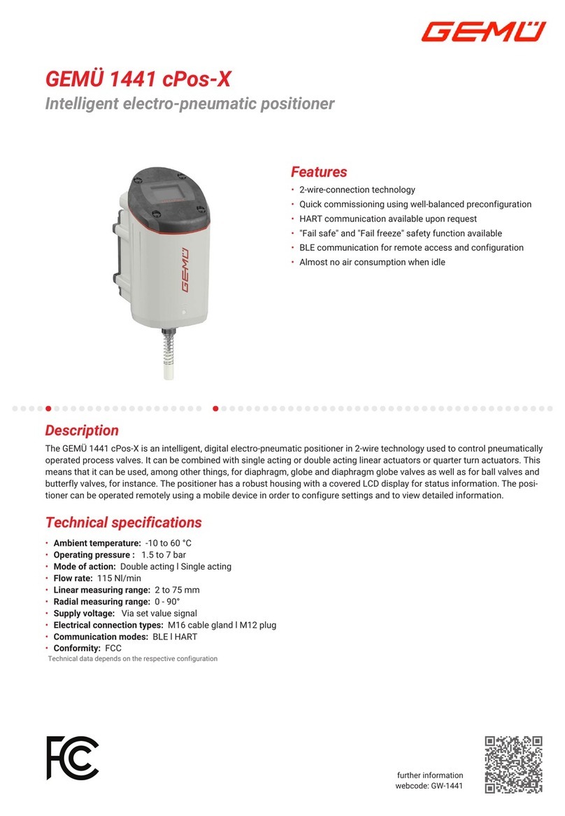
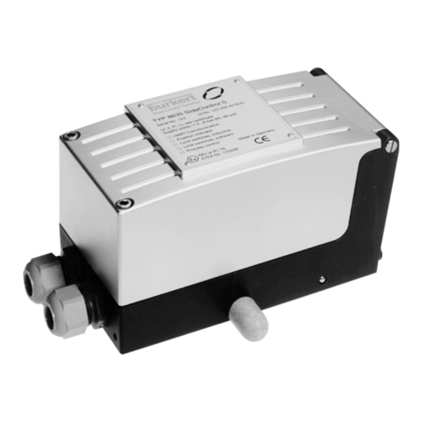
Fisher-Rosemount 3660 User manual

D101402X012
Type 3660 and 3661 Positioners
Contents
Introduction 3. . . . . . . . . . . . . . . . . . . . . . . . . . . . . . .
Scope of Manual 3. . . . . . . . . . . . . . . . . . . . . . . . . . . . .
Description 3. . . . . . . . . . . . . . . . . . . . . . . . . . . . . . . . . .
Specifications 3. . . . . . . . . . . . . . . . . . . . . . . . . . . . . . .
Installation 3. . . . . . . . . . . . . . . . . . . . . . . . . . . . . . . . .
Positioner Mounting 5. . . . . . . . . . . . . . . . . . . . . . . . . .
Mounting on the Type 1250, 1250R, and
3024S Actuators 5. . . . . . . . . . . . . . . . . . . . . . . . .
Mounting on Baumann Actuators 7. . . . . . . . . . . . .
Mounting on the Type 657 and 667 Actuators 8. .
Feedback Lever Assembly and
Range Spring Installation 11. . . . . . . . . . . . . . . . . .
Pressure Connections 14. . . . . . . . . . . . . . . . . . . . . . .
Supply Connection 13. . . . . . . . . . . . . . . . . . . . . . . . .
Output Connection 13. . . . . . . . . . . . . . . . . . . . . . . . .
Instrument Connection 15. . . . . . . . . . . . . . . . . . . . .
Diagnostic Connections 15. . . . . . . . . . . . . . . . . . . .
Vent Connection 15. . . . . . . . . . . . . . . . . . . . . . . . . . . .
Electrical Connections for
Type 3661 Positioners 15. . . . . . . . . . . . . . . . . . . .
Calibration 16. . . . . . . . . . . . . . . . . . . . . . . . . . . . . . . .
Split Range Operation 18. . . . . . . . . . . . . . . . . . . . . . .
Type 3660 Bypass Operation 18. . . . . . . . . . .
Principle of Operation 19. . . . . . . . . . . . . . . . . . .
Maintenance 19. . . . . . . . . . . . . . . . . . . . . . . . . . . . . .
Changing the Positioner Action 20. . . . . . . . . . . . . . .
Changing the Range Spring 20. . . . . . . . . . . . . . . . . .
Changing the Input Signal Range on
Type 3660 Positioners 21. . . . . . . . . . . . . . . . . . . .
Removing the Positioner from the Actuator 21. . . . .
Center-Bolt Mounting on the Type 1250,
1250R, 3024S and Baumann Actuators 21. . . .
Clamp Mounting on the Type 1250,
1250R and 3024S Actuators 21. . . . . . . . . . . . . .
Mounting Bracket/U-Bolt Mounting on
Type 657, and 667 Actuators 21. . . . . . . . . . . . .
Changing the Input Module
Diaphragm Assembly 21. . . . . . . . . . . . . . . . . . . . .
Figure 1. Type 3660 Positioner Mounted on a
Baumann Actuator
W7174 / IL
Disassembling and Assembling Relay
Components 22. . . . . . . . . . . . . . . . . . . . . . . . . . . . .
Disassembling and Assembling the Bypass
Valve 23. . . . . . . . . . . . . . . . . . . . . . . . . . . . . . . . . . .
Replacing the Type 3661 Converter Module 23. . . .
Parts Ordering 23. . . . . . . . . . . . . . . . . . . . . . . . . . . .
Parts Kits 24. . . . . . . . . . . . . . . . . . . . . . . . . . . . . . . . .
Repair Kits 24. . . . . . . . . . . . . . . . . . . . . . . . . . . . . . . . .
Mounting Kits 24. . . . . . . . . . . . . . . . . . . . . . . . . . . . . .
Parts List 24. . . . . . . . . . . . . . . . . . . . . . . . . . . . . . . . . .
Positioner Common Parts 24. . . . . . . . . . . . . . . . . . . .
Diagnostic Connections 25. . . . . . . . . . . . . . . . . . . . . .
Mounting Parts 25. . . . . . . . . . . . . . . . . . . . . . . . . . . . .
Loop Schematics 31. . . . . . . . . . . . . . . . . . . . . . . .
Instruction Manual
Form 5265
December 2000 Type 3660 and 3661

Type 3660 and 3661
2
Table 1. Specifications
Available Configuration
Type 3660: Single-acting pneumatic valve
positioner
Type 3661: Single-acting electro-pneumatic valve
positioner
Input Signal(1)
Type 3660
J0.2 to 1.0 bar (3 to 15 psig),
J0.4 to 2.0 bar (6 to 30 psig), or
Jsplit range (see tables 2 and 3)
Type 3661:
J4 to 20 mA dc constant current with 30 V dc
maximum compliance voltage.
Jsplit range is also available, see tables 2 and 3
Equivalent Circuit (Type 3661)
120 ohms shunted by three 5.6 V zener diodes
Output Signal(1)
Type: Pneumatic pressure as required by the
actuator up to full supply pressure
Action:
JDirect (increasing input signal pressure increases
positioner output),
JReverse (increasing input signal pressure
decreases positioner output)
Supply Pressure(1)
Recommended: 10% above actuator requirements
Maximum: 6.2 bar (90 psig) or pressure rating of
actuator, whichever is lower
Performance(1)
Independent Linearity: ±1% of output span
Hysteresis: 0.5% of output span(4)
Deadband: 0.1% of input span
Electromagnetic Interference (EMI) (Type 3661)
When tested per SAMA Standard PMC 33.1-1978,
change in steady-state deviation is less than ±1% in
an electromagnetic field classified as 3-abc with a
field strength of 30 V/m. Positioner is tested with
cover on and with external wiring in rigid metal
conduit
These instruments have the CE mark in accordance
with the Electromagnetic Compatibility (EMC)
Directive. They meet the requirements of
EN50081-1 (emmissions for light industry) and
EN50082-2 (immunity for industrial environment).
Positioner Adjustments
Span: JAdjustable up to 20 mm (0.75 inch) stem
travel, or JAdjustable from 20 mm (0.75 inch) to
50 mm (2 inch) stem travel
Zero: 0 to 100%
Gain: 0.5 to 6% PB (proportional band)(5)
Output Volume Damping: Loop dynamic response
adjustment
Delivery Capacity(2)
1.4 Bar (20 Psig) Supply: 4.3 normal m3/hour
(150 scfh)
2.4 Bar (35 Psig) Supply: 6.6 normal m3/hour
(230 scfh)
Exhaust Capacity(2)
1.4 Bar (20 Psig) Supply: 4.8 normal m3/hour
(170 scfh)
2.4 Bar (35 Psig) Supply: 7.4 normal m3/hour
(260 scfh)
Steady-State Air Consumption(1)(2)(3)
Type 3660: 0.16 normal m3/hour (6.0 scfh) at 1.4
bar (20 psig) supply pressure. 0.21 normal m3/hour
(7.9 scfh) at 2.4 bar (35 psig) supply pressure
Type 3661: 0.24 normal m3/hour (8.8 scfh) at 1.4
bar (20 psig) supply pressure. 0.33 normal m3/hour
(12.3 scfh) at 2.4 bar (35 psig) supply pressure
Operating Influences(1)
Supply Pressure: 70 mbar (1 psig) change in
supply pressure changes the actuator stem position
less than 0.16%(6) of travel
Operative Temperature Limits(1)
Type 3660 without Pressure Gauges: –40 to
120°C (–40 to 250°F)
Type 3660 with Pressure Gauges: –40 to 60°C
(–40 to 140°F)
Type 3661 without Pressure Gauges: –40 to 80°C
(–40 to 180°F)
Type 3661 with Pressure Gauges: –40 to 60°C
(–40 to 140°F)
Hazardous Area Classification
Refer to Hazardous Area Classification bulletins for
approvals
– Continued –

Type 3660 and 3661
3
Table 1. Specifications (Continued)
Housing Classification (Type 3661)
IP 54 per IEC 60529, NEMA 3 (FM) and Enclosure
3 (CSA): Mounting orientation requires vent location
to be below horizontal.
Mounting
The positioner can be mounted in one of four
different configurations. See figure 2 for mounting.
Pressure Connections
1/4-inch NPT female
Conduit Connection for Type 3661
1/2-inch NPT (M20 or PG13 adaptors, optional)
Maximum Valve Stem Travel
Two ranges:
J50 mm (2 inch) to 20 mm (0.75 inch) minimum;
J20 mm (0.75 inch) adjustable to lesser travel with
standard input signal
Options
Type 3660:
JInstrument and output pressure gauges,
JIntegrally mounted bypass valve
Type 3661: Output pressure gauge
Approximate Weight
Type 3660: 1.2 kg (2.6 pounds)
Type 3661: 1.4 kg (3.0 pounds)
Vent Connection
1/4-inch NPT female
1. This term is defined in ISA Standard S51.1.
2. Normal m3/hr—normal cubic meters per hour (0°C and 1.01325 bar absolute); Scfh—standard cubic feet per hour (60°F and 14.7 psia).
3. Air consumption at a gain setting of 1/2 turn.
4. Hysteresis value at a gain setting of 1/2 turn.
5. Adjusting the gain (PB) adjustment changes the nozzle flapper relationship. This nozzle flapper change affects the actuator/positioner response time.
6. At supply pressure of 2.4 bar (35 psig).
Introduction
Scope of Manual
This instruction manual includes installation, operation,
calibration, maintenance, and parts ordering
information for the Type 3660 and 3661 positioners.
Refer to separate instruction manuals for information
on the actuator and control valve.
Only personnel qualified through training or experience
should install, operate, or maintain the positioner. If
there are any questions concerning the instructions in
this manual, contact your Fisher sales office or sales
representative before proceeding.
Description
The Type 3660 pneumatic and Type 3661
electro-pneumatic, single-acting positioners are used
with Fisher Controls Type 657, 667, 1250, and 1250R
actuators. These positioners can also be mounted on
Gulde 3024S and Baumann actuators. Figure 1 shows
a Type 3660 positioner mounted on a Baumann
actuator.
The positioner mounts on the actuator and provides
the desired plug position for a specific input signal.
The Type 3660 positioner accepts a pneumatic signal
and the Type 3661 accepts a 4 to 20 milliampere dc
input signal.
Specifications
Specifications for the Type 3660 and 3661 positioners
are shown in table 1.
Installation
Normally, a positioner is shipped with the actuator. If
so, the factory mounts and calibrates the positioner
and connects the positioner to actuator tubing. If the
positioner is ordered separately from the actuator,
perform the appropriate mounting procedure. Refer to
the appropriate instruction manuals for actuator and
valve installation procedures.
WARNING
Avoid personal injury and property
damage from sudden release of process
pressure. Before mounting the
positioner on a valve in service:
DDisconnect any operating lines
providing air pressure, electric power, or
a control signal to the actuator. Be sure
the actuator cannot suddenly open or
close the valve.

Type 3660 and 3661
4
Input Signal Positioner Output
Direct
0.2 to 1.0 bar (3 to 15 psig)
0.4 to 2.0 bar (6 to 30 psig)
4 to 20 mA
Reverse
1.0 to 0.2 bar (15 to 3 psig)
2.0 to 0.4 bar (30 to 6 psig)
20 to 4 mA
Up to 6.2 bar (90 psig)
For split range signal refer to tables 2 and 3
Figure 2. Mounting Configurations
ACTUATOR: AIR-TO-RETRACT
POSITIONER ACTION: DIRECT
(INCREASING INPUT SIGNAL INCREASES
OUTPUT PRESSURE TO ACTUATOR)
INPUT SIGNAL
AIR SUPPLY
OUTPUT
PILOT SHAFT
1
ACTUATOR: AIR-TO-RETRACT
POSITIONER ACTION: REVERSE
(INCREASING INPUT SIGNAL DECREASES
OUTPUT PRESSURE TO ACTUATOR)
INPUT SIGNAL
AIR SUPPLY
OUTPUT
FEEDBACK
PLATE
2
ACTUATOR: AIR-TO-EXTEND
POSITIONER ACTION: REVERSE
(INCREASING INPUT SIGNAL DECREASES
OUTPUT PRESSURE TO ACTUATOR)
INPUT SIGNAL
AIR SUPPLY
OUTPUT
1
ACTUATOR: AIR-TO-EXTEND
POSITIONER ACTION: DIRECT
(INCREASING INPUT SIGNAL INCREASES
OUTPUT PRESSURE TO ACTUATOR)
INPUT SIGNAL
AIR SUPPLY
OUTPUT
2
NOTES:
WHEN MOUNTING ON BAUMANN ACTUATORS, INSTALL FEEDBACK PLATE SO LIP IS UP. INSTALL FEEDBACK LEVER ARM
ASSEMBLY, PRELOADED, SO PILOT SHAFT IS ON TOP OF THE FEEDBACK PLATE.
WHEN MOUNTING ON BAUMANN ACTUATORS, INSTALL FEEDBACK PLATE SO LIP IS DOWN. INSTALL FEEDBACK LEVER ARM
ASSEMBLY, PRELOADED, SO PILOT SHAFT IS UNDERNEATH THE FEEDBACK PLATE.
1
2
17B9106-B
17B9105-B
38B0195-B
A4035-2 / IL
DUse bypass valves or completely
shut off the process to isolate the valve
from process pressure. Relieve process
pressure on both sides of the valve.
Drain the process media from both sides
of the valve.
DVent the power actuator loading
pressure and relieve any actuator spring
precompression.
DUse lock-out procedures to be sure
that the above measures stay in effect
while you work on the equipment.

Type 3660 and 3661
5
DFor 3661 positioners in intrinsically
safe areas, current monitoring during
operation must be with an approved
meter for hazardous areas in order to
avoid personal injury or property
damage caused by an explosion or fire.
Positioner Mounting
Mounting on the Type 1250, 1250R, and
3024S Actuators
During the following mounting procedures, refer to
figures 3, 24, and 25 for key number locations. Figure
3 shows keys 61 through 78 and 101 through 104.
Other key numbers are shown in either figure 24 for
the Type 3660 positioner or figure 25 for the Type
3661 positioner. Two mounting methods are available,
center-bolt mounting and clamp mounting.
1. Determine the positioner mounting configuration
from figure 2. The actuator size, actuator travel, and
positioner action must be known. If center-bolt
mounting is desired, be certain the actuator is
equipped with tapped holes in the posts.
2. Thread the hex head screws with washers (keys 69
and 70) several turns into the stem connector. The
feedback plate (key 68) is reversible and must be
positioned so that the pilot shaft (key 19A) will operate
correctly in the slot of the feedback plate. For actuator
travels between 20 and 30 mm (0.787 and 1.18
inches) (for 3024S actuators, travel ranges between
16 and 32 mm), position the feedback plate so the
long portion of its slot, when bolted to the stem
connector, is closest to the positioner as shown in
figure 4. For travels greater than 30 mm (1.18 inches),
reverse the position of the feedback plate as shown in
figure 4.
a. For size 30 and 34 actuators with all travels and
for size 45 actuators with travel greater than 30 mm
(1.18 inches), position the feedback plate (key 68)
between the stem connector and washers and
tighten the hex head screws (key 69).
b. For size 45 actuators with travel between 20 and
30 mm (0.787 and 1.18 inches) (16 and 32 mm for
3024S actuators), attach the feedback adaptor (key
103) to the feedback plate (key 68) using machine
screws, lockwashers, and wedge nuts (keys 102,
101, and 104). The feedback plate and the wedge
nuts must be assembled as shown in the lower
right portion of figure 3. Use the mounting holes in
the feedback adaptor and position it as indicated in
figure 4. Then, position the feedback plate between
the stem connector and washers and tighten the
hex head screws (key 69).
3. Unscrew the two machine screws (key 24), and
remove the positioner cover (key 21).
Center-Bolt Mounting
a. As shown in figure 5, a thin knockout section is
cast across the mounting hole in the housing.
Check to make certain this knockout section has
been removed. If the knockout section has not
been removed, use a punch to knock it out.
b. Attach the positioner to the actuator using a
sealing washer and hex head screw (keys 71 and
72).
c. Install the feedback lever assembly and range
spring.
Clamp Mounting
a. Install a hex nut (key 66) on one end of each of
two studs (key 65). Turn the nuts all the way to the
end of the threads.
b. Thread the end of each stud (key 65), (the end
with hex nut—key 66), into the back of the
positioner housing (key 1) as far as the studs will
go. Tighten both nuts against the housing.
c. Set the actuator at mid-travel using a manual
loading regulator.
d. With the finger end of the bracket (key 64)
toward the positioner pressure connections as
shown in figure 3, place the bracket and washers
(key 67) over the studs (key 65). Thread the hex
nuts (key 66) several turns onto the studs.
Note
Do not install the range spring in the
following step. Feedback lever assembly
(key 19) installation in the next step is
only temporary to permit verifying
alignment.
e. Install the positioner on the actuator by placing
the bracket (key 64) around the appropriate
actuator leg. Visually center the center line of the
slot in the feedback plate (key 68) with the center
line of the hole in the housing. Then, tighten the
nuts (key 66) only tight enough to prevent the
positioner from moving on the actuator leg. Locate
the feedback lever assembly (key 19) so that it may
be temporarily installed into the positioner housing
(key 1) and the feedback plate (key 68) to verify
alignment. Do not install the range spring at this
time. Place the pilot shaft (key 19A) in the slot of
the feedback plate, and, at the same time, insert

Type 3660 and 3661
6
Figure 3. Positioner Mounting on Type 1250, 1250R, and 3024S Actuators
41B3946-F/DOC
NIPPLE MOUNTED
FILTER REGULATOR
CLAMP MOUNT
SECTION
AĆA
CENTER BOLT
MOUNT
SIZE 45 WITH TRAVEL BETWEEN
20 AND 30 mm (0. 8 AND 1.18 INCHES)
AA
WEDGE NUT
(KEY 104) FEEDBACK
PLATE
(KEY 68)
FEEDBACK
ADAPTOR
(KEY 103)
LOCKWASHER
(K3Y 101)
MACHINE SCREW
(KEY 102)
FEEDBACK
LEVER
ASSEMBLY
FILTER
REGULATOR

Type 3660 and 3661
7
Figure 4. Feedback Plate Orientation with Positioner
Mounted on Type 1250, 1250R, and 3024S Actuators
B2260-1 / IL
FOR SIZE 30 AND 34 ACTUATORS WITH TRAVEL
BETWEEN 20 AND 30 mm (0. 8 AND 1.18 INCHES)
FOR SIZE 30,34 AND 45 ACTUATORS WITH
TRAVEL GREATER THAN 30mm (1.18 INCHES)
FOR SIZE 45 ACTUATORS WITH TRAVEL BETWEEN
20 AND 30 mm (0. 8 AND 1.18 INCHES)
POSITIONER
ACTUATOR LEG STEM CONNECTOR
FEEDBACK
PLATE
PILOT SHAFT FEEDBACK LEVER
ASSEMBLY
POSITIONER
ACTUATOR LEG STEM CONNECTOR
FEEDBACK
PLATE
PILOT SHAFT
FEEDBACK LEVER ASSEMBLY
STEM CONNECTOR
FEEDBACK
PLATE
ACTUATOR STEM
FEEDBACK
ADAPTOR
VALVE STEM
USE THESE HOLES
WHEN MOUNTING
THE FEEDBACK
ADAPTOR TO THE
FEEDBACK PLATE
the feedback shaft in the hole of the positioner
housing. Depress the feedback lever assembly
inward until it stops against the housing. Make
certain the slots in both the feedback lever
assembly and the feedback plate are horizontal
with each other and that the feedback lever
assembly and the feedback plate are parallel with
each other. If necessary, correct alignment by
loosening the hex nuts (key 66) and moving the
positioner on the actuator leg as required.
Figure 5. Actuator Center-Bolt Mounting
A4949-1 / IL
THIN SECTION
f. Tighten the two hex nuts (key 66) to secure the
positioner to the actuator leg.
g. Install the feedback lever assembly and range
spring.
Mounting on Baumann Actuators
During the following mounting procedures, refer to
figures 2, 5, 6, 24, and 25. Key numbers are shown in
either figure 24 for the Type 3660 positioner or figure
25 for the Type 3661 positioner.
1. Determine the positioner mounting configuration
from figure 2. The actuator size, actuator travel, and
positioner action must be known.
2. Attach the feedback plate to the actuator stem
connector by locating the feedback plate between the
actuator stem and valve stem nuts (figure 6) as
follows:
DIf after the positioner is mounted the feedback
lever assembly will be on the left side of the positioner,
install the feedback plate so the lip is up.
DIf after the positioner is mounted the feedback
lever assembly will be on the right side of the
positioner, install the feedback plate so the lip is down.
3. Unscrew the two machine screws (key 24), and
remove the positioner cover (key 21).
4. As shown in figure 5, a thin knockout section is cast
across the mounting hole in the housing. Check to
make certain this knockout section has been removed.
If the knockout section has not been removed, use a
punch to knock it out.
5. For air to extend actuators, the feedback lever
assembly must be installed into the positoner and

Type 3660 and 3661
8
Figure 6. Feedback Plate Installation for Baumann Actuators
ACTUATOR
STEM
VALVE
STEM
FEEDBACK LEVER
ARM ASSEMBLY
FEEDBACK
PLATE
PILOT SHAFT
IF AFTER MOUNTING POSITIONER, THE FEEDBACK LEVER ARM AS-
SEMBLY WILL BE ON THE LEFT SIDE OF THE POSITIONER, INSTALL THE FEED-
BACK PLATE SO THE LIP IS UP. INSTALL THE FEEDBACK LEVER ARM AS-
SEMBLY, PRELOADED, SO THE PILOT SHAFT IS ABOVE THE PLATE.
IF AFTER MOUNTING POSITIONER, THE FEEDBACK LEVER ARM ASSEMBLY
WILL BE ON THE RIGHT SIDE OF THE POSITIONER, INSTALL THE FEEDBACK
PLATE SO THE LIP IS DOWN. INSTALL THE FEEDBACK LEVER ARM ASSEMBLY,
PRELOADED, SO THE PILOT SHAFT IS BELOW THE PLATE.
1
1
A7223 / IL
preloaded before attaching the positioner to the
actuator.
6. Attach the positioner to the actuator using a sealing
washer and hex head screw (keys 71 and 72).
7. Install the feedback lever assembly and range
spring.
Mounting on the Type 657 and 667
Actuators
During the following mounting procedures, refer to
figures 7, 24, and 25 for key number locations. Figure
7 shows keys 61 through 63, 69 and 70, 73 through
78, and 82 through 93. Other key numbers are shown
in either figure 24 for the Type 3660 positioner or
figure 25 for the Type 3661 positioner.
1. Determine the positioner mounting configuration
from figure 2. The actuator size, actuator travel, and
positioner action must be known.
Note
The actuator bench set spring load must
be released before removing the stem
connector cap screws. Refer to the
appropriate actuator instruction manual
for this procedure. After installing the
positioner and mounting hardware, reset
the actuator bench set.
2. Attach the connector bracket (key 87) to the
actuator stem connector using washers and cap
screws (keys 70 and 69), but do not tighten the
screws. Refer to figures 7 and 8 for the proper
orientation of the connector bracket with respect to the
actuator stem connector. The face of the stem
connector should be perpendicular to the legs of the
actuator yoke.
3. Refer to figure 8 for the feedback arm (key 88)
location with respect to the connector bracket (key 87).
Position the feedback arm so that the pilot shaft (key
19A) will operate correctly in the slot of the feedback
arm. For actuator travels between 19 and 30 mm (0.75
and 1.18 inches), position the feedback arm so that
the long portion of the feedback arm slot, when
fastened to the connector bracket, is closest to the
positioner (see figure 8). For travels greater than 30
mm (1.18 inches) reverse the feedback arm so the slot
in the feedback arm is opposite the positioner (see
figure 8).
4. Attach the feedback arm (key 88) to the connector
bracket (key 87) using machine screws, washers and
hex nuts (keys 91, 92 and 93), but do not tighten the
hex nuts.
5. Unscrew the two machine screws (key 24), and
remove the positioner cover (key 21).
6. As shown in figure 5, a thin knockout section is cast
across the mounting hole in the housing. Check to
make certain that this knockout section has been
removed. If the knockout section has not been
removed, use a punch to knock it out.
7. Set the actuator at mid-travel using a manual
loading regulator.
8. Install the stud clamp (key 83) in the mounting
bracket (key 82). Place the mounting bracket against
the outside of the actuator leg. Attach the two U-bolts
(key 84) and the mounting bracket to the actuator leg
using washers and hex nuts (key 85 and 86), but do
not tighten the nuts. Depending on the positioner
action, it may be necessary to straddle the travel
indicator scale located on the inside of the actuator
leg.
Note
Do not install the range spring in the
following step. Feedback lever assembly
(key 19) installation in the next step is
only temporary to permit verifying
alignment.
9. Attach the positioner to the stud clamp (key 83)
using the sealing washer and hex nut (keys 89 and
90), but do not tighten the nut. Visually center the
center line of the slot in the feedback arm (key 88) with
the center line of the hole in the housing. Then, tighten
the nuts (keys 90 and 86) only tight enough to prevent
the positioner and mounting bracket from moving on
the actuator leg. Locate the feedback lever assembly

Type 3660 and 3661
9
Figure 7. Positioner Mounting on Type 657 and 667 Actuators
FILTER
REGULATOR
41B6744-D/DOC
SECTION
AĆA
TO POSITIONER
OUTPUT
TYPE 66
NIPPLE MOUNTED
FILTER REGULATOR
AA
APPLY LUB

Type 3660 and 3661
10
Figure 8. Feedback Arm Orientation with Positioner Mounted on
Type 657 and 667 Actuators
B2256-1 / IL
SIZES 30 THROUGH 40 ACTUATORS WITH
TRAVEL UP TO 30 mm (1.18 INHES)
SIZES 45 THROUGH 60 ACTUATORS WITH
TRAVL UP TO 30 mm (1.18 INCHES)
SIZES 30 THROUGH 40 ACTUATORS WITH
TRAVEL GREATER THAN 30 mm (1.18 INCHES)
SIZES 45 THROUGH 60 ACTUATORS WITH
TRAVEL GREATER THAN 30 mm (1.18 INCHES)
(key 19) so it may be temporarily installed into the
positioner housing (key 1) and the feedback arm (key
88) to verify alignment. Do not install the range spring
at this time. Place the pilot shaft (key 19A) in the slot
of the feedback arm, and, at the same time, insert the
feedback shaft in the hole of the positioner housing.
Depress the feedback lever assembly inward until it
stops against the housing. Make certain the slots in
both the feedback lever assembly and feedback arm
are horizontal and that the feedback lever assembly
and the feedback arm are parallel with each other. If
necessary, correct alignment by loosening the hex
nuts (keys 86 and 90) and either moving the stud
clamp in the mounting bracket or moving the mounting
bracket on the actuator leg.
10. Tighten the nuts that were not tightened in the
previous steps.
a. Tighten the hex nut (key 90) to secure the
positioner to the stud clamp (key 83).
b. Tighten the four hex nuts (key 86) to secure the
mounting bracket (key 82) to the actuator leg.
c. Tighten the machine screws and hex nuts (key
91 and 93) to secure the feedback arm (key 88) to
the connector bracket (key 87).
d. Tighten the hex head screws (key 69) to secure
the connector bracket (key 87) to the actuator stem
connector.
11. Install the feedback lever assembly and range
spring.
Feedback Lever Assembly and Range
Spring Installation
Key numbers are shown in either figure 24 for the
Type 3660 positioner or figure 25 for the Type 3661
positioner. Key numbers for the feedback lever
assembly are shown in figure 26.
CAUTION
The range spring (key 30) and feedback
lever assembly (key 19) must be
installed together. Installing the range
spring after the feedback lever assembly

Type 3660 and 3661
11
Figure 9. Installing the Feedback Lever Assembly
(Key19) on the Positioner
RETAINING SCREW
(KEY 19P)
ANTI-ROTATING
SLOT
W7367 / IL
is installed may result in damage to the
lever assembly (key 17) flexures.
1. Refer to figure 9. Loosen the retaining screw
(key 19P) located in the positioner housing until it is
fully retracted into the housing.
2. On the feedback lever assembly (key 19), loosen
the zero adjustment screw (key 19S) until it is fully
retracted into the clinch nut.
3. On the feedback lever assembly, loosen the hex
nut (key 19D) so the pilot shaft (key 19A) moves freely
in the slot.
CAUTION
In the next step, be sure the feedback
spring (key 19N) hooks on the spring pin
(key 19R) opposite the zero adjustment
screw. If the feedback spring does not
hook on the spring pin correctly, the
feedback spring may be damaged during
feedback lever assembly (key 19)
installation.
4. Refer to figure 10. Verify that the feedback spring in
the feedback lever assembly bushing is hooked on the
end of the spring pin opposite the zero adjustment
screw.
Note
When installing the feedback lever
assembly bushing, be sure the
anti-rotating slot aligns with the
retaining screw (key 19P).
Figure 10. Positioning Feedback Spring
ZERO
ADJUSTMENT
COVER
FEEDBACK
SHAFT
SPRING PIN
FEEDBACK SPRING
FEEDBACK SPRING MUST
HOOK AROUND SPRING PIN
END OPPOSITE THE ZERO
ADJUSTMENT SCREW
27B9999-D
A7224 / IL
5. Position the feedback lever assembly (key 19) so
that the pilot shaft (key 19A) will rest on the feedback
plate or slide into the slot of the feedback arm (key 88)
after installation.
6. Be sure the anti-rotating slot aligns with the
retaining screw (key 19P), then install the feedback
lever assembly bushing partially into the positioner.
Slight tension on the feedback spring (key 19N) may
be required to get the anti-rotating slot to align with the
retaining screw.
Note
The reason for partially sliding the
feedback lever assembly (key 19) into
the housing is to permit installing the
range spring (key 30) without damaging
the lever assembly (key 17) flexures.
Installing the range spring after the
feedback lever assembly is completely
installed may damage the lever
assembly flexures.
7. Tighten the retaining screw (key 19P) until the
screw engages the anti-rotating slot so that the
bushing does not rotate, but leave the screw loose
enough so that the bushing can slide freely into the
housing.
8. Refer to figures 11 and 12. Select the appropriate
range spring (key 30) from tables 2 and 3. Place the
range spring in the positioner so that one end of the
spring is fully in the lever assembly slot. Next, rotate
the feedback lever assembly so that:
Dthe other end of the range spring aligns with the
slot in the feedback shaft, and

Type 3660 and 3661
12
Figure 11. Range Spring Installation
LEVER
ASSEMBLY
FEEDBACK
SHAFT
W7366 / IL
Figure 12. Range Spring Alignment
A5211 / IL
Dthe pilot shaft (key 19A) is either above or below
the actuator feedback plate or engages the slot in the
feedback arm (key 88).
Note
The feedback lever assembly bushing
will no longer slide freely in the housing
after it is placed in the normal operating
position due to the side loading of the
retaining screw (key 19P) on the
anti-rotating slot.
9. Center the range spring (key 30) in the lever
assembly (key 17) and feedback shaft slots; then push
the feedback lever assembly bushing into the housing
far enough so that the spring is retained without
holding it.
Figure 13. Pressing the Feedback Lever Assembly Busning
into the Positioner
W7365 / IL
CAUTION
Installation of the feedback lever
assembly (key 19) prior to installation of
the range spring (key 30) may result in
damage to the lever assembly (key 17)
flexures. The range spring must be in
place before pushing the feedback lever
assembly bushing fully into the
positioner housing.
10. Ensure the range spring (key 30) is properly
aligned as shown in figure 12, then, as shown in
figure 13, place hands on both sides of the positioner
and press firmly until the feedback lever assembly
bushing shoulder is against the positioner housing
(figure 14).
11. While holding the feedback lever assembly
bushing securely against the housing, tighten the
retaining screw (key 19P). The feedback lever
assembly bushing should be tight against the
positioner housing as shown in figure 14.
12. Move the pilot shaft (key 19A) to the approximate
span position shown in table 3
Note
To ensure proper positioner
performance, make certain, after
alignment and all tightening is
completed, that there is clearance
between the face of the pilot shaft and
the feedback arm.
13. Install the feedback lever assembly cover
(key 19T) with cover screw (key 19U).

Type 3660 and 3661
13
Figure 14. Feedback Lever Assembly in Operating Position
BUSHING(AGAINST
POSITIONER
HOUSING)
ZERO ADJUST
(SELF-LOCKING)
W7366 / IL
14. Verify the positioner action. Note the letters D and
R on the flapper (key 10). If the letter D is nearest the
adjustment screw (key 18), the positioner is set for
direct action. To change the positioner action, refer to
the Changing Positioner Action procedure in the
“Maintenance”section. If the action is changed,
complete the “Calibration”section before putting the
unit into operation.
15. Install the positioner cover (key 21) and secure
with the two machine screws (key 24). Make certain
the Fisher logo reads correctly and the vent is pointing
downward. Continue with the “Pressure Connections”
section.
Pressure Connections
Installing a Type 3660 or 3661 positioner requires
tubing and pressure fittings. The fittings, tubing, and
mounting parts required depend on the type number
and optional equipment, such as filter/regulator and
bypass valve. See figure 15 for the location of the
positioner pressure connections.
WARNING
The positioner is capable of providing
full supply pressure to connected
equipment. To avoid personal injury and
equipment damage, make sure the
supply pressure never exceeds the
maximum safe working pressure of any
connected equipment.
Supply Connection
WARNING
Personal injury or property damage may
occur from an uncontrolled process if
the supply medium is not clean, dry,
oil-free, or noncorrosive gas. Industry
instrument air quality standards
describe acceptable dirt, oil, and
moisture content. Due to the variability
in nature of the problems these
influences can have on pneumatic
equipment, Fisher Controls has no
technical basis to recommend the level
of filtration equipment required to
prevent performance degradation of
pneumatic equipment. A filter or filter
regulator capable of removing particles
40 microns in diameter should suffice
for most applications. Use of suitable
filtration equipment and the
establishment of a maintenance cycle to
monitor its operation is recommended.
Connect a clean, dry air source to the supply
connection of the positioner. Use 3/8-inch tubing or
1/4-inch pipe for the supply line. A supply air filter or a
filter regulator capable of removing particles 40
microns in diameter is recommended. The supply
pressure should not exceed the following limits:
1. For the positioner, do not exceed the maximum
pressure rating of 6.2 bar (90 psig).
2. For actuator pressure, refer to the appropriate
actuator instruction manual for maximum allowable
pressures.
3. For the valve body assembly, do not exceed the
maximum allowable thrust of the specific valve.
Output Connection
Connect the OUTPUT connection to the actuator
diaphragm casing connection. Use 3/8-inch, 1/4-inch,
or 6 mm tubing, or 1/4-inch pipe between the actuator
and the positioner.

Type 3660 and 3661
14
ACTUATOR CENTERLINE TO POSITIONER
Type
Size
Dim X
Type Size mm Inch
657/667
30
34
40
45/46
50/60
92.2
95.3
104.9
108.0
128.5
3.63
3.75
4.13
4.25
5.06
1250 30
34
45
86.0
86.0
110.0
3.39
3.39
4.33
3024S 1.21
1.31
1.41
83.5
87.5
87.5
3.29
3.44
3.44
Baumann
16in2
32in2
54in2
70in2
53.8
71.4
71.4
71.4
2.12
2.81
2.81
2.81
Figure 15. Typical Mounting Dimensions and Connections
31B3959-C
C0686-3/IL
ACTUATOR POST
CENTERLINE
34.32
(1.35)
49.2
(1.94)
191.2
(7.53)
93
(3.66) 49
(1.93)
34.32
(1.35)
ACTUATOR POST
CENTERLINE
142.2
(5.60)
49.2
(1.94) 93
(3.66)
ACTUATOR
CENTERLINE
ACTUATOR
CENTERLINE
DIM X
122.3
(4.81)
30
(1.18))
30
(1.18)
21.5
(.85))
1/4–INCH NPT
OUTPUT
CONNECTION
1/4–INCH NPT
INSTRUMENT
CONNECTION
1/4–INCH NPT
SUPPLY
CONNECTION
1/4–INCH NPT
SUPPLY
CONNECTION
1/4–INCH NPT
INSTRUMENT
CONNECTION
1/4–INCH NPT
OUTPUT
CONNECTION
122.3
(4.81)
67.5
(2.66) DIM X
30
(1.18))
30
(1.18)
21.5
(.85))
27.5
(1.08)
1/2–INCH NPT
TYPE 3661 I/P
ONLY
mm
(INCH)
67.5
(2.66)
0.5
(.02)

Type 3660 and 3661
15
Figure 16. FlowScannertValve Diagnostic System Connections
12B8052-A
A6084*/IL
Instrument Connection
Connect the control device output to the positioner
INSTRUMENT connection. Use 3/8-inch tubing to
1/4-inch pipe.
The Type 3661 electro-pneumatic positioner requires a
4 to 20 milliampere dc current input signal from the
control device. For connections to the Type 3661, refer
to the “Electrical Connections for Type 3661
Positioners”section.
Diagnostic Connections
To support diagnostic testing of
valve/actuator/positioner packages, special connectors
and hardware are available. Typical connector
installations are shown in figure 16. The hardware
used includes 1/4-inch NPT pipe nipples and pipe tees
with 1/8-inch NPT pipe bushings for the connectors.
The connectors consist of 1/8-inch NPT bodies and
body protectors. If the diagnostic connectors are
ordered for a positioner with gauges, 1/8-inch stems
are also included.
Install the connectors and hardware between the Type
3660 or Type 3661 positioner and the actuator.
1. Before assembling the pipe nipple, pipe tee, pipe
bushings, actuator piping, and connector body, apply
sealant to all threads. Sealant is provided with the
diagnostic connectors and hardware.
2. Turn the pipe tee to position the connector body
and body protector for easy access when doing the
diagnostic testing.
Vent Connection
The Type 3660 and 3661 positioners are equipped
with a 1/4-inch NPT vent connection in the cover.
WARNING
If a flammable, toxic, corrosive, or
reactive gas is to be used as the supply
pressure medium, personal injury or
property damage could result from fire
or explosion of accumulated gas or from
contact with toxic, corrosive, or reactive
gas. The positioner/actuator assembly
does not form a gas-tight seal, and when
the assembly is enclosed, a remote vent
line, adequate ventilation, and necessary
safety measures should be used. A
remote vent pipe alone cannot be relied
upon to remove all hazardous gas. Vent
line piping should comply with local and
regional codes and should be as short
as possible with adequate inside
diameter and few bends to reduce case
pressure buildup.
Electrical Connections for Type 3661
Positioners
Refer to figures 17 and 18 when making electrical
connections. Use the 1/2-inch NPT (or M20 thread)
conduit connection for installation of field wiring. Run
the input wires through the conduit, and connect the
positive wire from the control device to the positioner +
terminal and the negative wire from the control device

Type 3660 and 3661
16
Figure 17. Equivalent Circuit
21B2335-D
A6012/IL
5.6V 5.6V 5.6V 60 Ohms
60 Ohms
4 - 20 mA +
–
+
–
+
––+
1
CONTROL
DEVICE
POSITIONER
HOUSING
TERMINAL
BLOCK
FIELD WIRING
EARTH
GROUND
NOTE:
FOR TROUBLESHOOTING OR MONITORING OPERATION,
AN INDICATING DEVICE CAN BE A VOLTMETER ACROSS
A 250 OHM RESISTOR OR A CURRENT METER.
1
Figure 18. Typical Field-Wiring Diagram
A3875*/IL
to the positioner –terminal. Do not over tighten the
terminal screws. The maximum torque is
0.45 NSm (4 lbfSin.).
Calibration
The following calibration procedures are for the
adjustment of the pneumatic positioner. For the Type
3661 positioner, there are no adjustments within the
converter portion of the positioner. All adjustments are
accomplished within the pneumatic portion of the
positioner.
WARNING
Avoid personal injury or equipment
damage from sudden release of process
fluid. Before calibration:
DIsolate the valve from the process,
and
DRelease process pressure.
Refer to figure 24 (Type 3660) or figure 25 (Type
3661) for key number locations unless otherwise
indicated. Adjustment locations are shown in figure 19.
1. If mounting a new positioner on an actuator or if the
positioner action has not been changed, do not
perform steps 2 through 7.
2. If the positioner action has been changed or if the
positioner has had maintenance performed on it,
complete steps 3 through 17.
3. If the cover (key 21) has not been removed,
unscrew the two machine screws (key 24), and
remove the cover.
4. Release all pressure from the positioner.
Disconnect the positioner output tubing to the actuator.
If the positioner is equipped with an output gauge, plug
the positioner output connection. If the positioner is not
equipped with an output gauge, provide a gauge to
monitor positioner output and connect it to the
positioner output connection.
5. Set the supply pressure to the required setting. Set
the gain(1) (proportional band) adjustment screw at a
nominal value by turning it clockwise until it stops, and
then turning it counterclockwise 1 turn.
Note
To improve holding of the calibration
tool as used in step 6, the actuator may
be used to create the load (manual
pressure) by winding up the positioner
range spring. The direction of windup,
looking at the spring from outside the
housing, must be clockwise. This
windup will create a torsional force over
the input diaphragm through the lever
assembly. The spring is automatically
wound up in two of the
positioner/actuator mounting positions
when the loading pressure is removed.
These are left-hand mounting on a
spring-to-close actuator and right-hand
mounting on a spring-to-open actuator
(refer to figure 2). In the other two
mounting positions, the actuator must
be pressurized to 100 percent input to
create the spring holding force.
1. Adjusting the gain (PB) adjustment changes the nozzle flapper relationship. This
nozzle flapper change affects the actuator/positioner response time.

Type 3660 and 3661
17
Figure 19. Adjustment Locations (Equivalents of Pressures Shown in This Drawing
are:6 bar = 86 psig, 4 bar = 58 psig, and 1.4 bar = 20 psig)
28B0006-B / DOC
INCREASE
TRAVEL
6. Remove the calibration tool (key 6) from the cover.
Place the calibration tool between the lever assembly
(key 17) and the input diaphragm assembly (key 28).
When making the following adjustment, apply manual
pressure to the lever assembly over the input
diaphragm assembly to hold the calibration tool in
place. Loosen the lock nut (key 57), and turn the
adjusting screw (key 18) until the output is 50% ±10%
of supply pressure. For example, if supply pressure is
2.4 bar, set the output to 1.2 bar ±0.24 bar.
7. Lock the adjusting screw (key 18) with the lock nut
(key 57). After the adjustment is complete, remove the
calibration tool and replace it in the positioner cover.
8. Release all pressure from the positioner. Remove
the plug or the gauge that was installed in step 4, and
reconnect the output tubing to the actuator.
9. Turn on supply pressure. Set the input signal to the
minimum value.
10. Remove the cover (key 19T) from the feedback
lever assembly (key 19).
11. Set the travel (span) adjustment to the desired
actuator travel by loosening the hex nut (key 19D) and
sliding the pilot shaft (key 19A) to the desired setting
on the feedback lever assembly (key 19). The travel
settings are marked in millimeters on the feedback
lever assembly.
12. Set the gain (PB) adjustment and/or the output
volume damping adjustment to a setting that provides
the best actuator/positioner response. Observe the
gain dependency on the air supply pressure as shown
in the graph of figure 19. The gain adjustment
restrictor for air delivery should be fully open for large
size actuators and adjusted to a mid-value for smaller
size actuators with 225 cm2(35 square inches) or less
diaphragm area. Start by setting the gain adjustment
at approximately one turn open, and, if the output
volume damping adjustment is used, turn it clockwise
to decrease the air delivery.
13. Adjust the valve stem position by rotating the zero
adjustment screw (key 19S).
14. Set the input signal to the maximum value.
15. Readjust the travel (span) adjustment to achieve
correct actuator travel.
Note
When a travel (span) adjustment is
made, there will be a zero shift.
16. Repeat steps 11 through 15 as necessary to
achieve correct actuator travel.

Type 3660 and 3661
18
Table 2. Range Spring Selection for Fisher Actuators
TYPE 3660 3660 3661
VALVE STEM TRAVEL
Split
0.2 to 1.0 bar
(3 to 15 psig)
Input Signal
0.4 to 2.0 bar
(6 to 30 psig)
Input Signal 4 to 30 mAdc
Input Signal
VALVE STEM TRAVEL
WHEN USING
TYPES 3660 AND 3661
RANGE SPRING
PART NUMBER
(KEY 30)
Bar Psig Bar Psig
Inp
u
t
Signal
mm Inches
(KEY
30)
One Way 1:1 0.2 to 1.0 3 to 15 0.4 to 2.0 6 to 30 4 to 20 20 to 50 0.787 to 1.969 11B3880 X012
Two Way 2:1 0.2 to 0.6
0.6 to 1.0 3 t0 9
9 to 15 0.4 to 1.2
1.2 to 2.0 6 to 18
18 to 30 4 to 12
12 to 20 20 to 50 0.787 to 1.969 11B3881 X012
Three Way
3:1
0.2 to 0.5
0.5 to 0.8
0.8 to 1.0
3 to 7
7 to 11
11 to 15
0.4 to 1.0
1.0 to 1.5
1.5 to 2.0
6 to 14
14 to 22
22 to 30
4 to 9.33
9.33 to 14.66
14.66 to 20 15 to 33.3 0.591 to 1.311 11B3881 X012
Table 3. Range Spring Selection for Baumann Actuators
TYPE 3660 3661 VALVE STEM TRAVEL
0.2 to 1.0 bar
(3 to 15 Psig)
Input Signal
0.4 to 2.0 bar
(6 to 30 Psig)
Input Signal
4 to 20 mA dc
Input Signal 12.7 to 19.1 mm
(1/2 to 3/4 inch) 19.1 to 50 mm
(3/4 to 2 inch)
Split Range
Bar
(Psig)
Span
Bar
(Psi)
Range
Bar
(Psig)
Span
Bar
(Psi)
Range
mA Span
mA
Range Spring
Part Number
(key 30)
Approximate
Pilot Shaft
Setting(1)
mm (Inch)
Range Spring
Part Number
(key 30)
Approximate
Pilot Shaft
Setting(1)
mm (Inch)
One Way
1:1 0.2 to 1.0
(3 to 15) 0.8
(12) 0.4 to 2.0
(6 to 30) 1.6
(24) 4 to 20 16 17B0662X012 89 (3.50) 17B0662X012 129 (5.09)
Two Way
2:1
0.2 to 0.6
(3 to 9)
0.6 to 1.0
(9 to 15)
0.4
(6)
0.5 to 1.2
(6 to 18)
1.2 to 2.0
(18 to 30)
0.8
(12) 4 to 12
12 to 20 8 11B3880X012 92 (3.63) 11B3881X012 92 (3.63)
Three Way
3:1
0.2 to 0.5
(3 to 7)
0.5 to 0.8
(7 to 11)
0.8 to 1.0
(11 to 15)
0.3
(4)
0.5 to 1.0
(6 to 14)
1.0 to 1.5
(14 to 22)
1.5 to 2.0
(22 to 30)
0.6
(8)
4 to 9.33
9.33 to 14.66
14.66 to 20 5.33 11B3881X012 70 (2.75) 11B3881X012 137 (5.38)
Four Way
4:1
0.2 to 0.4
(3 to 6)
0.4 to 0.5
(6 to 9)
0.5 to 0.8
(9 to 12)
0.8 to 1.0
(12 to 15)
0.2
(3)
0.5 to 0.8
(6 to 12)
0.8 to 1.2
(12 to 18)
1.2 to 1.6
(18 to 24)
1.6 to 2.0
(24 to 30)
0.4
(6)
4 to 8
8 to 12
12 to 16
16 to 20
4 11B3881X012 95 (3.75) ––– – ––
1. Pilot shaft setting is the A dimension in figure 20.
17. Install the cover (key 19T) on the feedback lever
assembly (key 19) with cover screw (key 19U).
18. Install the positioner cover (key 21) and secure
with the machine screws (key 24). Make sure the
Fisher logo reads correctly and the vent is pointing
downward.
Split-Range Operation
Type 3660 and 3661 positioners can be used for
split-range operation with the instrument input signal
from a single controller or another instrument split
between two or three control valves. Tables 2 and 3
show some typical split ranges for the positioners. To
change from a full range to a split range, change the
range spring (key 30, figure 24 or 25) to the
appropriate spring shown in the tables. Complete the
Changing Range Spring portion of the Maintenance
section. Refer to tables 2 and 3 for valve stem travel
available with split range operation.
Type 3660 Bypass Operation
Type 3660 positioners may be supplied with a bypass
assembly.
CAUTION
Do not use bypass operation when the
positioner is reverse acting or is in
split-range operation. In these cases,
bypassing the positioner, sends the
input signal directly to the actuator.
Such a change will affect the desired
operation and possibly upset the

Type 3660 and 3661
19
Figure 20. Pilot Shaft Setting
A
PILOT
SHAFT
(KEY 19A) FEEDBACK LEVER
ASSEMBLY (KEY 19)
FEEDBACK SHAFT
LOCATION
38B0195-B / DOC
system. Use bypass operation only
when the instrument signal range is the
same as the positioner output range
required for normal actuator operation.
Labels on the bypass body assembly (key 41, figure
23), and a pointer on the bypass lever (key 42 in figure
23) indicate if the input signal from the instrument goes
to the positioner or directly to the control valve
actuator.
With the pointer of the bypass lever over the word
POSITIONER, the instrument pressure goes to the
positioner and the output pressure of the positioner
goes to the actuator.
With the pointer of the bypass lever over the word
BYPASS, the instrument pressure goes directly to the
actuator.
Note
A difference between the input signal
pressure and the positioner output
pressure could cause a transient bump
in the controlled system when the
bypass lever is moved to BYPASS.
With a reverse-acting or split-range positioner, the
bypass lever may be secured in the POSITIONER
position so that bypass cannot be used. To lock the
bypass lever in the POSITIONER position, shut off the
instrument and supply pressure to the positioner.
Then, move the bypass lever (key 42 in figure 23) so
the pointer is over the word POSITIONER. Align the
hole in the pointer with the hole in the body assembly
and thread the plastic wire tie (key 79 in figure 23)
through both holes to secure the bypass lever.
Principle of Operation
Refer to figure 21 for the operational schematic.
The instrument pressure acts on the input module,
which controls the flapper-nozzle system of the relay.
Supply pressure is applied to the relay, and the output
pressure of the relay is supplied to the control valve
actuator.
For a direct-acting positioner, increases in instrument
pressure cause the input module to pivot the beam.
The beam pivots the flapper and restricts the nozzle.
The nozzle pressure increases and causes the relay
assembly to increase output pressure to the actuator.
With a direct-acting actuator, this increased pressure
moves the actuator stem downward. Stem movement
is fed back to the beam by means of a feedback lever
and range spring, which causes the flapper to pivot
slightly away from the nozzle to prevent any further
increases in relay output pressure. The positioner is
once again in equilibrium but at a higher instrument
pressure, a slightly different flapper position, and a
new actuator stem position.
A decrease in instrument pressure decreases nozzle
pressure, which allows the relay to bleed off actuator
loading pressure.
Operation of a reverse-acting positioner is similar
except that the position of the flapper is reversed from
that shown in figure 21. The reversed position uses the
alternate flapper pivot point so that increases in
instrument pressure rotate the flapper away from the
nozzle to reduce nozzle pressure.
With a Type 3661 electro-pneumatic positioner, the
electro-pneumatic (I/P) converter provides a 0.2 to 1.0
bar (3 to 15 psig) output pressure proportional to the 4
to 20 milliampere input signal. The 0.2 to 1.0 bar (3 to
15 psig) output pressure becomes the input signal
pressure to the input module.
Maintenance
Positioner parts are subject to normal wear and must
be inspected and replaced as necessary. The
frequency of inspection and replacement depends
upon the severity of service conditions. The following
procedure describes disassembly and reassembly of
the positioner. When inspection or repairs are
required, disassemble only those parts necessary to
accomplish the job. When reassembly is complete,
make adjustments as described in the Calibration
section.
Due to the care Fisher Controls takes in meeting all
manufacturing requirements (heat treating,
dimensional tolerances, etc.), use only replacement
parts manufactured by Fisher.

Type 3660 and 3661
20
Figure 21. Operational Schematic
FLAPPER
DIRECT
ACTING
PIVOT REVERSE
ACTING
PIVOT
NOZZLE
OUTPUT
RANGE
SPRING RELAY
GAIN ADJA
A
FEEDBACK
PLATE
FEEDBACK
LEVER
PILOT
SHAFT
INPUT
MODULE
BEAM
PIVOT
SUPPLY RANGE
SPRING RELAY
GAIN ADJ
SUPPLY
A
A
INPUT SIGNAL
I/P CONVERTER
INPUT
MODULE
BEAM
PIVOT
SECTION AĆA
TYPE 3660
TYPE 3661
31B3960-C
B2152-4 / IL
WARNING
Avoid personal injury or equipment
damage from sudden release of process
fluid. Before disassembly:
DIsolate the valve from the process,
DRelease process pressure, and
DVent the actuator loading pressure.
For intrinsically safe areas, current
monitoring during operation must be
with an approved meter for hazardous
areas in order to avoid personal injury or
property damage caused by an
explosion or fire.
Changing the Positioner Action
This section explains changing the positioner action
from direct to reverse or reverse to direct. With direct
action, the positioner output pressure increases as the
instrument input signal to the positioner increases.
With reverse action, the positioner output pressure
decreases as the input signal to the positioner
increases. To change the action of a positioner that is
already mounted on an actuator, remove the positioner
from the actuator. Refer to the Removing the
Positioner from Actuator section. Refer to figure 24 or
25 for key number locations.
1. Unscrew the two captive cover screws and remove
the cover (key 21). Carefully lift the flapper spring at
the location shown by key 10.
2. Slide out the flapper (key 9) and rotate it so that the
desired letter (D or R for direct and reverse) is nearest
the adjusting screw (key 18). When inserting the
flapper, be sure the end of the flapper engages the
groove in the end of the screw and that the flapper
spring (key 10) sets into the V-notches of the flapper.
3. Mount the positioner to the opposite actuator leg as
explained in the Positioner Mounting section and
shown in figure 2.
4. Refer to the “Calibration”section for the calibration
procedure.
Changing the Range Spring
Refer to figure 24 or 25 for key number locations.
1. Unscrew the two captive cover screws and remove
the cover (key 21). Loosen the retaining screw
This manual suits for next models
1
Table of contents
Popular Valve Positioner manuals by other brands
SMC Networks
SMC Networks IP8100-0 1 X83 Series Operation manual
Dresser
Dresser Universal RAI Installation operation & maintenance
Vahle
Vahle APOS installation manual
Spirax Sarco
Spirax Sarco SP7-10 Installation and maintenance instructions
RTK
RTK DAC RE 3581 Series Installation and operating instructions
ESCO Technologies
ESCO Technologies ETS-LINDGREN 2301 user manual
Samson
Samson 3785 series Mounting and operating instructions

Samson
Samson 3730-0 Mounting and operating instructions

SMC Networks
SMC Networks IP8000 manual
Will Burt
Will Burt PositionIt PI-35 Operator's manual
Flowserve
Flowserve Logix 3000MD Series Technical bulletin
M2 Antenna Systems
M2 Antenna Systems FGAE1000-D1-W-COS-A-H manual
