SCHIEBEL SRG2 Series User manual

Positioner SRG 2xx
DS-ENGLISH-SRG2XX-V2.00-2012.07.17
SEC-DS-ENGLISH-SRG2XX-V2.00-2012.07.17
Positioner SRG2xx
1 General
The SRG1xx positioner (see Figure 1) facilitates the control of an electric actuator by
means of a set point with current output 0(4)...20mA. A potentiometer with a resistance
value of 100Ωto 10kΩis used as an actual value in the actuator.The position control of
the actuator is carried out using the SRG2xx, i.e. the positioner ensures that the actual
value and thus the position of the actuator follows the set point.
Figure 1: Symbol
2 Operation and electrical connection
The set point current I1is conducted via terminal 77 and the current measuring diode to the resistor R1. The
set point I1(see Figure 3 and 4) can be measured at the measuring points using a measuring device (internal
resistance max. 10Ω)) without impairing operation. The actual value (actuator position) is determined in the
SRG2xx from the position of the actual value potentiometer (connected to the terminals 74 to 76) coupled with
the actuator. This actual value is compared with the set point in the positioner. If both values are equal except
for a residual difference (adjustable with potentiometer D), none of the two relays (K3, K4) on the positioner
picks up (see Figure 2).
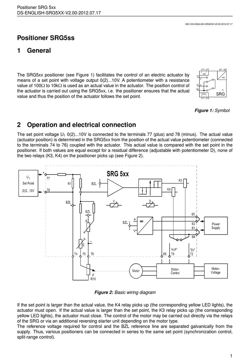
Figure 2: Basic wiring diagram
If the set point is larger than the actual value, the K4 relay picks up (the corresponding yellow LED lights), the
actuator must open. If the actual value is larger than the set point, the K3 relay picks up (the corresponding
yellow LED lights), the actuator must close. The control of the motor may be carried out directly via the relays
of the SRG or via an additional reversing starter unit depending on the motor type.
The reference voltage required for control and the BZL reference line are separated galvanically from the
1

3 Connection model
Positioner SRG 2xx
DS-ENGLISH-SRG2XX-V2.00-2012.07.17
supply. Thus, various positioners can be connected in series to the same set point (synchronization control,
split-range control).
3 Connection model
The positioner can be supplied in sub-unit terminal screw block (see Figure 3) or in insert card block (see
Figure 4) version.
The connection model is determined by the third digit of the designation (SRGxx1 for insert card block (see
Figure 4) and SRGxx2 for sub-unit terminal screws (see Figure 3)).
Figure 3: SRG 2x2 Figure 4: SRG 2x1
4 Instructions for adjustment
Jumper J1:
You can determine the behaviour of the positioner in case of failure of the set point and the actual value (e.g.
wire fracture), respectively, by means of the J1 jumper. This function becomes active if an input signal is lower
than a certain threshold (see technical data). A response of the control is signalled by the red LED Hs (set
point monitoring) and Hi (actual value monitoring), respectively.
When operating the SRG1xx with current signals 0...20mA this control has to be switched off.
The following functions are possible:
Jumper at Z (see Figure 5): with the response of the monitoring the K3 relay picks up. This corresponds to
the control command "CLOSE". Jumper at 0 (see Figure 6): with the response of the monitoring both relays
are released, the actuator stops. Jumper at A (see Figure 7): with the response of the monitoring the K4 relay
picks up. This corresponds to the control command "OPEN". Jumper slanted (see Figure 8): The monitoring
is switched off (necessary with 0...20mA).
Figure 5: „CLOSE" Figure 6: „STOP" Figure 7: „OPEN" Figure 8: „0. . . 20mA"
Switching difference D:
The switching difference (see Figure 9) is adjusted using potentiometer D (see Figure 3 and 4). If a more exact
positioning of the actuator is desired, then the switching difference must be reduced. If the switching difference
2

Positioner SRG 2xx
DS-ENGLISH-SRG2XX-V2.00-2012.07.17 4 Instructions for adjustment
is too small, the actuator will start to oscillate. In case of actuator oscillation, the switching difference must be
increased. This is achieved by turning potentiometer D in a counter-clockwise direction.
Figure 9: Switchpoints of 3-point controller
Filter V:
The filter type used is a phase-zero filter. This filter limits the increase speed of the control deviation. The
effect of disturbances (high increase speed) is reduced effectively without impairing the control behaviour.
ATTENTION! A too large filter effect will cause the actuator to oscillate.
The filter effect is reduced by turning the potentiometer V in a clockwise direction.
Adjustment procedure:
Adjust actuator according to operating instructions for the actuator and set jumper J1 to position 0...20mA (see
Figure 8). Set filter effect to minimum position by turning potentiometer V in clockwise direction.
Initial value: Feed 0mA (terminals 77 and 78) at set point input. The actuator moves into final position
"CLOSED" and is switched off via microswitches S1 (torque depending closing) or S3 (travel depending clos-
ing). Turn potentiometer A on SRG in clockwise direction until relay K3 is released (can be seen on LED).
Final value with set point 0...20mA: Feed 20mA (terminal 77 (plus) and terminal 78 (minus) at set point
input. The actuator moves in direction "OPEN" and the travel switch S4 (travel depending opening) and torque
switch S2 (torque depending opening), respectively, should switch. If S4 or S2 have not already switched, turn
potentiometer E in clockwise direction until S4 or S2 responds and relay K4 remains picked up. Then turn
potentiometer E slowly in counter-clockwise direction until relay K4 is released and K3 does not pick up yet
(switching difference).
Final value at set point 4...20mA: Feed 16mA (terminal 77 (plus) and terminal 78 (minus)) at set point input.
The actuator moves in direction "OPEN" and the travel switch S4 (travel depending opening) and torque switch
S2 (torque depending opening), respectively, should switch. If S4 or S2 have not already switched, turn poten-
tiometer E in clockwise direction until S4 or S2 responds and relay K4 is released. Increase nominal value to
20mA, K4 picks up. Turn potentiometer A in counter-clockwise direction until relay K4 is released and K3 does
not pick up yet.
Control and correction of adjustment: Initial value: Feed minimum set point (0 or 4mA). The actuator
moves into final position "CLOSED". If S3 or S1 switches and K3 remains picked up, turn potentiometer A in
clockwise direction until K3 is released and K4 does not pick up yet. If K3 is released and S3 or S1 has not
switched yet, turn potentiometer A in counter-clockwise direction until S3 or S1 switches. If K3 remains picked
up, turn potentiometer A in clockwise direction until K3 is released and K4 does not pick up yet.
Final value: Feed set point 20mA. The actuator moves into final position "OPEN". If S4 or S2 switches and
K4 remains picked up, turn potentiometer E in counter-clockwise direction until K4 is released and K3 does not
3

5 Technische Daten
Positioner SRG 2xx
DS-ENGLISH-SRG2XX-V2.00-2012.07.17
pick up yet. If K4 is released and S3 or S1 has not switched yet, turn potentiometer E in clockwise direction
until S3 or S1 switches. If K4 remains picked up, turn potentiometer E in counter-clockwise direction until K4 is
released and K3 does not pick up yet.
Finally, determine the optimum adjustment of the switching difference with set point jumps. When turning
potentiometer D in a counter-clockwise direction, the switching difference is increased. The set point jumps
should be in the opposite direction (reverse clearance) and their size selected so that the actuator is able to
reach its nominal speed. Then the filter effect can be increased to the desired stability reserve again by turning
potentiometer V in a counter-clockwise direction. Finally, adjust behaviour in case of set point failure using
jumper J1.
5 Technische Daten
Supply voltage:
SRG21X ................................................220VAC,+10%/-15%,47...63Hz
SRG22X ................................................20...30VDC, smoothed;(+...63,-...61)
SRG23X.................................................110V AC,+10%/-15%,47...63Hz
Powerconsumption ............................................approx. 1,5VA
Ambienttemperature ...........................................-20...+60◦C
Setpointsignal .................................................0(4)...20 mA
Actual valuepotentiometer .....................................100Ω. . . 10kΩ
Switching threshold of the monitoring . . . . . . . . . . . . . . . . . . . . . . . . . . . max. 2,8mA
Switchingdifference ............................................0,5...5% offinal value
Hysteresis ......................................................approx. 25% ofswitchingdifference
Relay:
Switchingcapacity .......................................4A, 250VAC1
Mechanical life ...........................................20mill. cycles
Electromagnetic compatibility:
The function of the SRG can be influenced by heavy electro-magnetic disturbances. After interference decay,
the original function is restored and new alignment is not necessary. We advise to use shielded cables for the
signal lines of the SRG.
4
Table of contents
Other SCHIEBEL Valve Positioner manuals