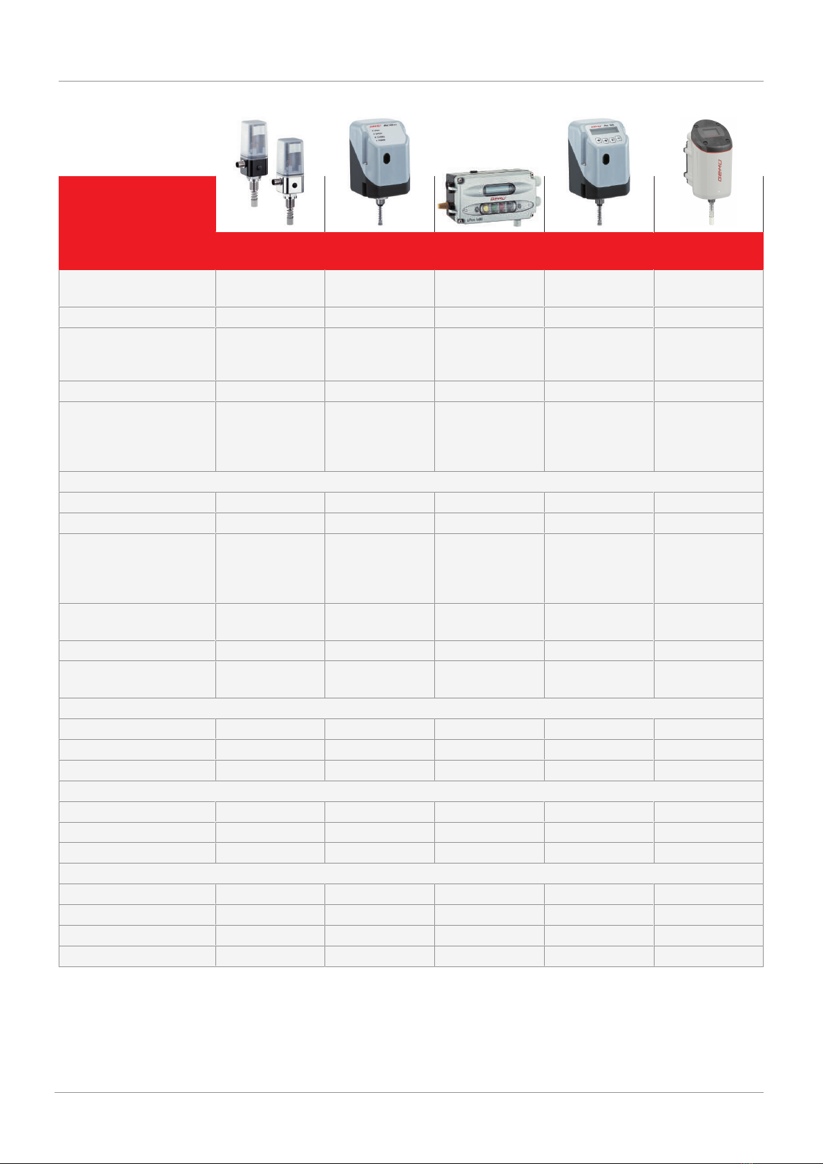
Order data
The order data provide an overview of standard configurations.
Please check the availability before ordering. Other configurations available on request.
Note: Pneumatic connecting components (union and compressed air tube) for the connection between the process valve and
positioner are included with each positioner.
Note: A valve specific mounting kit is required for assembly. For designing the mounting kit, the valve type, nominal size, control
function and actuator size must be stated.
Order codes
1 Type Code
2-wire 1441 cPos-X 1441
2 Fieldbus Code
Without 000
HART HAR
3 Accessory Code
Automation product A
4 Action Code
Single acting (fail safe) 1
Double acting (fail safe) 3
Single acting blocking (fail freeze) 5
Double acting blocking (fail freeze) 6
5 Device version Code
Positioner SA2
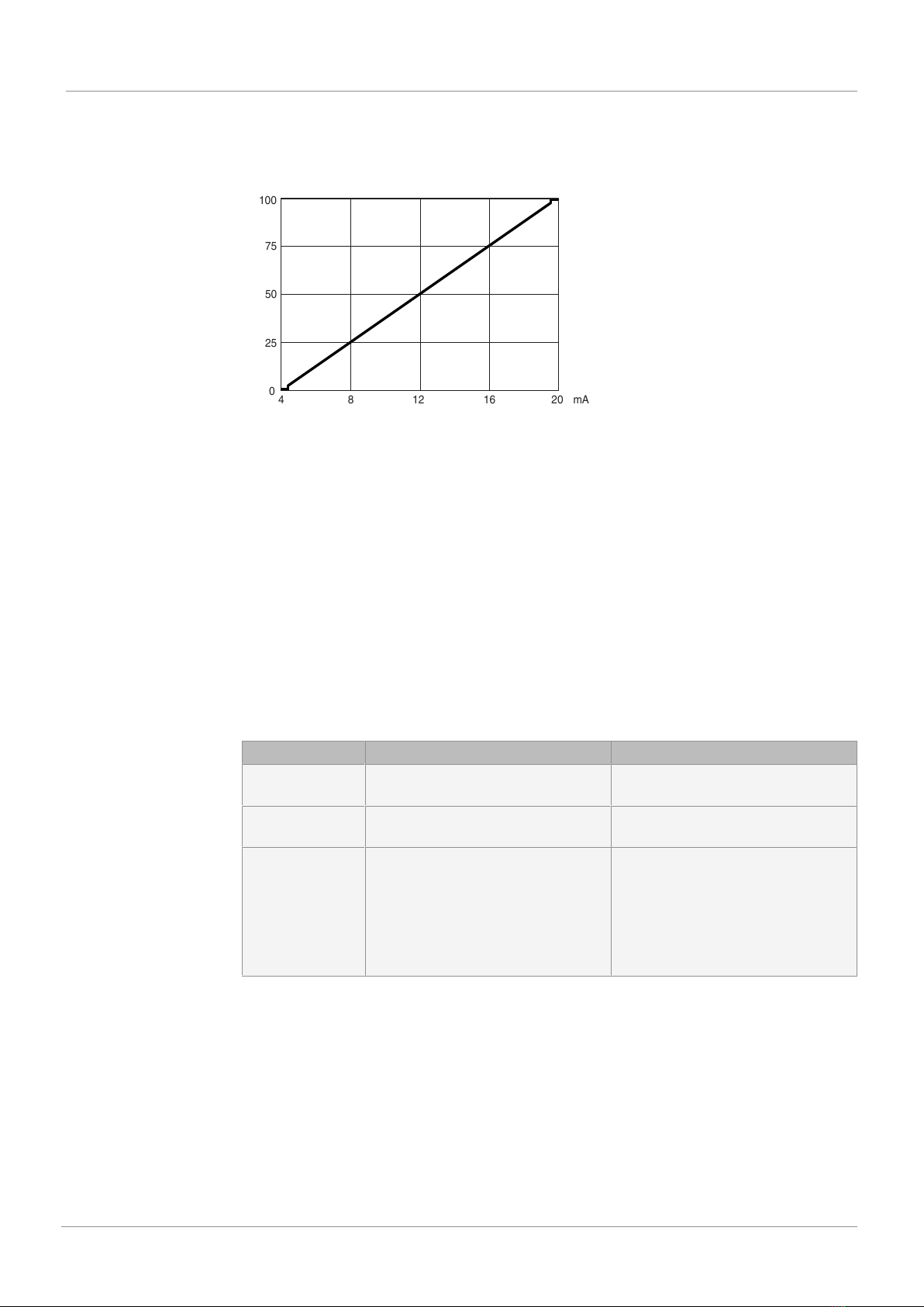
6 Signal type Code
4...20mA A
7 Pneumatic connection Code
G1/8 with 6mm plug-in coupling 3
G1/8 with 1/4" plug-in coupling U
8 Option Code
Analogue output, digital input and output C
9 Electrical connection Code
M12 plug 1
M16 x 1.5 cable gland 2
10 Flow rate Code
115 Nl/min 2
11 Travel sensor version Code
Potentiometer, 75 mm length 075
Remote potentiometer,
M12 connector
S01
12 Type of design Code
Without
Media wetted area cleaned to ensure suitability for paint
applications, parts sealed in plastic bag
0101
Inversed direction,
for quarter turn valves control function NO (2)
6960
13 CONEXO Code
Integrated RFID chip for electronic identification and
traceability
C
Order example
Ordering option Code Description
1 Type 1441 2-wire 1441 cPos-X
2 Fieldbus HAR HART
3 Accessory A Automation product
4 Action 1 Single acting (fail safe)
5 Device version SA2 Positioner
6 Signal type A 4...20mA
7 Pneumatic connection 3 G1/8 with 6mm plug-in coupling
8 Option C Analogue output, digital input and output
9 Electrical connection 1 M12 plug
10 Flow rate 2 115 Nl/min
11 Travel sensor version 075 Potentiometer, 75 mm length
12 Type of design Without
13 CONEXO C Integrated RFID chip for electronic identification and traceability
Order data
GEMÜ 1441
www.gemu-group.com 5 / 19