1 Design and principle of opera-
tion
The digital PROFIBUS-PA positioner is de-
signed for attachment to pneumatic control
valves. It is used to assign the valve stem po-
sition (controlled variable) to the control sig-
nal (reference variable). It compares the digi-
tal output signal to the travel of the control
valve and generates a corresponding pres-
sure signal as the output variable. As a re-
sult, the positioner requires auxiliary supply
air with a pressure of 1.4 to 6 bar. The nec-
essary electrical power is supplied by the bus
of the PROFIBUS-PA segment based on
IEC 61158-2 standard transmission technol-
ogy.
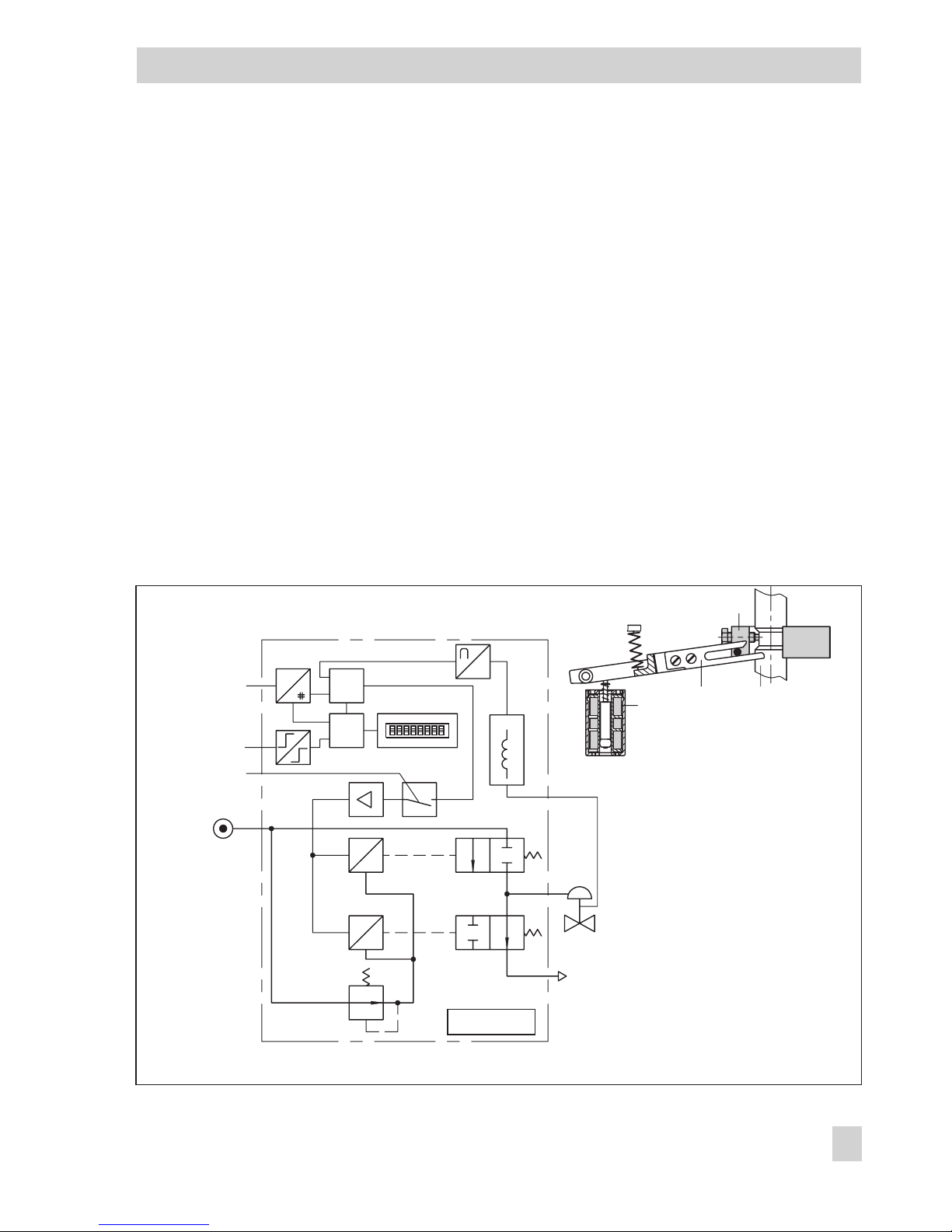
The positioner consists of an inductive,
contactless travel pick-off system and an
electrically controlled valve block comprising
two on/off valves and an electronic unit. This
unit contains two microcontrollers for pro-
cessing the control algorithm and managing
PROFIBUS communication.
If a deviation between the actual valve travel
(actual value) and the reference variable (set
point) occurs, the microcontroller produces
binary pulse-pause modulated signals to
control the two on/off valves, each of which
is assigned a downstream amplifier. One of
these valves controls the exhaust air, the
other the supply air.
The supply air valve (3) controls the connec-
tion between the supply air (7, supply air
pressure 1.4 to 6 bar) and the actuator
(pressurizing). The exhaust air valve (4) con-
trols the air exhausted from the actuator to
the atmosphere (venting). The on/off valves
can either have the switching states ("perma-
nently open", "permanently closed" or gen-
erate single pulses of changing widths). The
two valves cause the plug stem to move to a
position corresponding to the reference vari-
able. If there is no system deviation, both the
supply air valve and the exhaust air valve
are closed.
By default, the positioner is equipped with a
binary input for floating contacts, which ad-
ditionally signals the switching state of a
further field device via PROFIBUS.
Activating the write protection switch, which
is located next to the bus address in the
hinged lid, prevents the positioner settings
from being overwritten by PROFIBUS com-
munication.
Positioner with forced venting function:
The positioner is controlled by a 6 to 24 V
signal, causing the signal pressure to be ap-
plied to the actuator. If this voltage signal de-
creases, the signal pressure is shut off and
the actuator is vented. The springs in the ac-
tuator move the valve to its fail-safe position.
The forced venting function is included in all
positioners and can be activated/deactivated
as required over a switch. Refer to sec-
tion 4.3 for details.
1.1 Optional accessories
As a supplement to the standard positioner
version, the positioner can be equipped with
limit switches. Two proximity switches can be
used to indicate the valve's end positions in
safety-related circuits.
1.2 Communication
The positioner is completely controlled by
digital signal transmission according to the
PROFIBUS-PA Profile Class B based on
8EB 8382-1 EN
Design and principle of operation