RTK DAC RE 3581 Series User manual

Einbau- und Betriebsanleitung
Installation and Operating instructions
Instructions de montage et de service
Digitaler Stellungsregler mit Antriebskontrolle
Digital Positioner with actuator control
Positionneur digital
3581-8010
Baureihe / Series / Séries
RE 3581 DAC®
07/2009
Inhaltsverzeichnis
1 Allgemeine Informationen 2
2 Montage und Anschluß 2
3 Inbetriebnahme 3
4 Funktionsbeschreibung 5
5 Funktionsbeschreibung 5
6 Fehlermeldungen 8
Content
1 General Information 9
2 Installation and connection 9
3 Setting in motion 9
4 Description of Function 12
5 Setting in motion 12
6 Error codes 15
Index
1 Informations générales 16
2 Montage et raccordement 16
3 Mise en service 17
4 Modes de fonctionnement 20
5 Description fonctionnelle 20
6 Messages d’erreur 23
Anhang / Appendix/Annexe
1 Elektrischer Anschluß / Electric Connection / Raccordement électrique 24
2 Technische Daten / Technical data / Caractéristiques techniques 25

Einbau- und Betriebsanleitung
Installation and Operating instructions
Instructions de montage et de service
3581-8010
07/2009
1Allgemeine Informationen
Der RE 3581 (Digital Actuator Control) positioniert den Antrieb in Abhängigkeit des anstehenden Eingangssignals. Hierzu benötigt der Regler eine
Potentiometerrückmeldung über den gesamten Hub des Antriebes. Er hat einen integrierten Meßumformer der das Potentiometersignal in ein stetiges
Ausgangssignal 4..20mA umwandelt. Der RE 3581 vergleicht Eingangssignal mit Potentiometerstellung und steuert über die Relaisstufe den Antrieb in die
entsprechende Position. Die Anpassung des Potentiometers erfolgt während der Initialisierung automatisch und kann bei Bedarf digital über die Tastatur
abgeglichen werden.
Achtung! : Bevor Sie mit dem Einbau oder Betrieb von elektrischen Regelgeräten beginnen, lesen Sie bitte die Druckschrift "Warnung
vor Gefahren...".
Einbau und Inbetriebnahme sind nur dem hierfür ausgebildeten und qualifizierten Fachpersonal gestattet.
1.1 Tasten und LED-Anzeigen:
2Montage und Anschluß
Werkseitig wird der Regler in den Antrieb eingebaut und angeschlossen. Bei Auslieferung des Antriebe mit Ventil ist der Regler
eingestellt und somit betriebsbereit.
Bei nachträglichem Einbau des Reglers muß folgendes beachtet werden:
Schließen Sie bei nachträglichem Einbau Motor, Potentiometer, Eingangs- und Rückmeldesignal wie unter Kapitel 2.1 Elektrischer Anschluß
beschrieben an. Das Potentiometer muß so justiert werden, daß bei geschlossenem Ventil (0% Hub) ca. 10 % des ohmschen Wertes
zwischen Klemme 62 und 63 gemessen werden können. Bei geöffnetem Ventil sollten ca. 90% des ohmschen Wertes erreicht werden. Bei
gedrehtem Wirksinn müssen diese Werte an Klemme 61 und 62 gemessen werden. Bei Potentiometern ohne Anschlag ist darauf zu achten,
daß der Nullpunkt nicht überfahren wird.
Hierbei gilt:
Bei Durgangsventilen: 0% Hub (Ventil geschlossen) Poti ca. 10% des Wertes Ausgang 4 mA
100% Hub (Ventil offen) Poti ca. 90% des Wertes Ausgang 20 mA
Bei 3-Wege Ventilen: 0% Hub (Tor B geschlossen) Poti ca. 10% des Wertes Ausgang 4 mA
100% Hub (Tor B offen) Poti ca. 90% des Wertes Ausgang 20 mA
Bei umgekehrter Ansteuerung muß Klemme 61 mit 63 und Klemme K5 mit K6 getauscht werden.
2.1 Elektrischer Anschluß
Siehe Anhang
Hand / Automatik
Umschaltung
Man / Auto
Mode manuel / mode automatique
A
ntriebsspindel
Ausfahren Ventil schließen
Valve close
Vanne fermer
A
ntriebsspindel einfahren
Ventil öffnen
Valve open
Vanne ouvir
Betrieb
Operation
Fonctionner 4..20mA
Stellungsregler
Positioner
Positioneur
Öffnen
Opening
Ouvir
Schließen
Closing
Fermer
Handbetrieb
Manual mode
Manuel
Endlage
End position
Service
Service
Service

Einbau- und Betriebsanleitung
Installation and Operating instructions
Instructions de montage et de service
3581-8010
07/2009
3Inbetriebnahme
Die Inbetriebnahme darf erst erfolgen, wenn die Anschlüsse wie unter Kapitel 2.1 Elektrischer Anschluß beschrieben korrekt
erfolgt sind.
Bei Auslieferung mit Ventil ist der Regler werkseitig eingestellt. Eine erneute Anpassung an den Ventilhub ist nicht notwendig.
Der Regler ist sofort betriebsbereit.
Bei nachträglichem Einbau oder nach Austausch des Reglers oder des Potentiometers ist eine Initialisierung (Anpassung) an den Ventilhub
erforderlich.
Um den Regler neu zu initialisieren, muß immer die LED blinken siehe Kapitel 3.1 Löschen der Initialisierungsdaten (Reset).
3.1 Löschen der Initialisierungsdaten (Reset)
Um den Regler neu zu initialisieren müssen zuerst die aktuellen Initialisierungsdaten gelöscht werden.
Löschen der aktuellen Daten:
Halten sie alle 3 Tasten gleichzeitig länger als 10s gedrückt (bis alle LEDs leuchten).
Nachdem alle LEDs für ca. 2 sek. an waren blinkt die LED. Der Regler erwartet eine Paßworteingabe um mit der
Initialisierung starten zu können.
3.2 Initialisierung
Zur Initialisierung sind folgende Schritte notwendig und genau zu beachten:
1. Potentiometer wie oben beschrieben kontrollieren, gegebenenfalls einstellen.
2. Handbetrieb einschalten (siehe Kap. 4.1 Handbetrieb)
3. Paßwort eingeben (siehe Kap. 3.3 Ablaufschema der Initialisierung)
4. Ventil in Mittelstellung bringen (+/- 20%).
5. Handbetrieb ausschalten, Initialisierung startet automatisch.
6. Nach beendeter Initialisierung muß die Versorgungsspannung abgeschaltet und erneut eingeschaltet werden. Der Regler schaltet
automatisch in Handbetrieb. Die Daten wurden damit korrekt gespeichert. Schalten sie nun wieder in Automatikbetrieb.
Der Regler ist nun betriebsbereit!

Einbau- und Betriebsanleitung
Installation and Operating instructions
Instructions de montage et de service
3581-8010
07/2009
3.3 Ablaufschema der Initialisierung
RE 3581
betriebsbereit
Initialisierung
ok?
ja
Ventil in Mittelstellung +/-
20% fahren
und Taste
Handbetrieb aus
startet Initialisierung
automatische
Initialisierung läuft
Passwort eingeben
(siehe unten)
Passwort ok?
ja
aus
nein
nein
Achtung:
Bei 2-Weg Ventilen muß
Hub 100% manuell
eingestellt werden.
Manuelle Hubbegrenzung
drücken
Hub 100% bestimmen
Alle LEDs 3 sek. an
4..20mA
Alle LEDs 3 Sek. an
4..20mA
drücken
Hub 0% bestimmen
Antriebsvermessung
Passwort:
Eingabezeit max. 10s
Alle LEDs 3 sek.an
4..20mA
drücken an
an
unüberwachter
Handbetrieb aktiv
Alle 3 Taster gleichzeitg drücken bis alle LEDs leuchten
Wenn blinkt, Initialisierungsdaten gelöscht!

Einbau- und Betriebsanleitung
Installation and Operating instructions
Instructions de montage et de service
3581-8010
07/2009
3.4 unüberwachter Handbetrieb
Nach korrekter Eingabe des Paßwortes kann das Ventil im Handbetrieb mit den "Öffnen" und "Schließen" Tasten bewegt werden.
Fahren sie das Ventil in Mittelposition +/- 20%. Die Initialisierung darf auf keinen Fall in der Nähe der Endlagen gestartet werden.
4Funktionsbeschreibung
Der Regler arbeitet in 4 verschiedenen Betriebsarten.
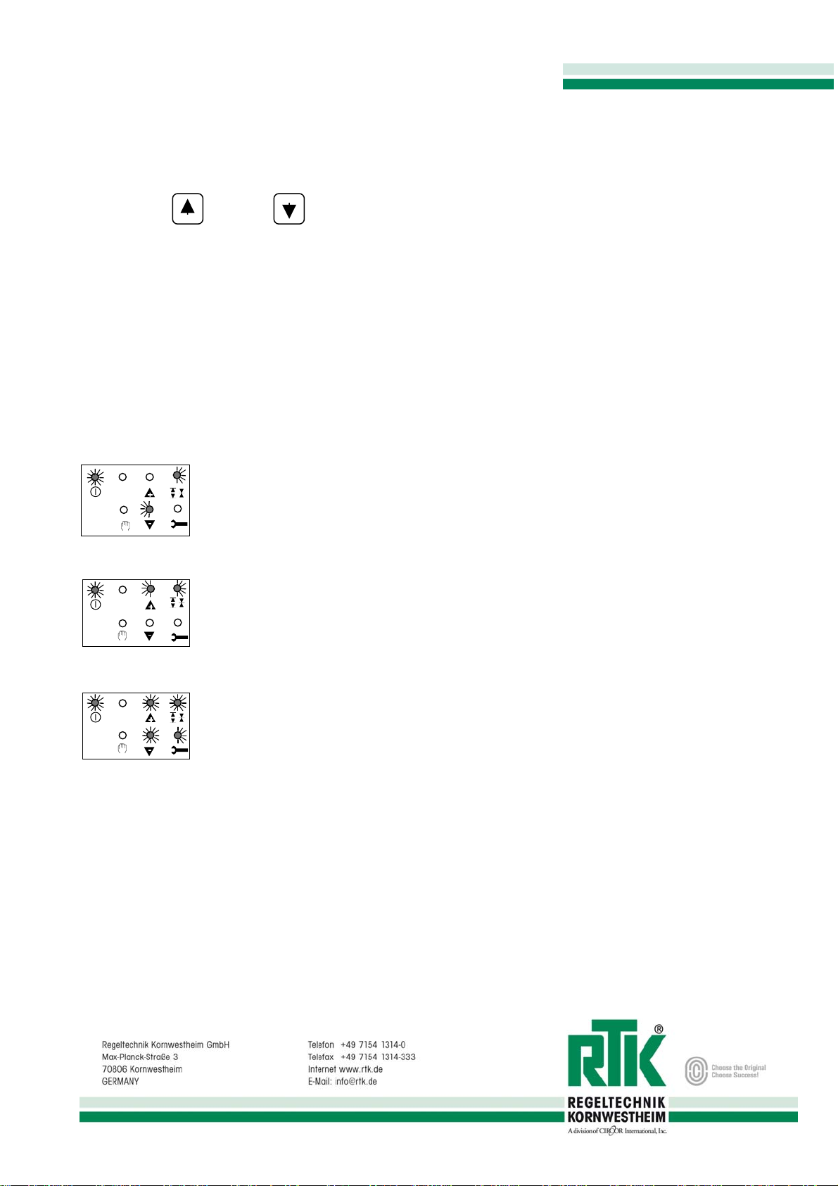
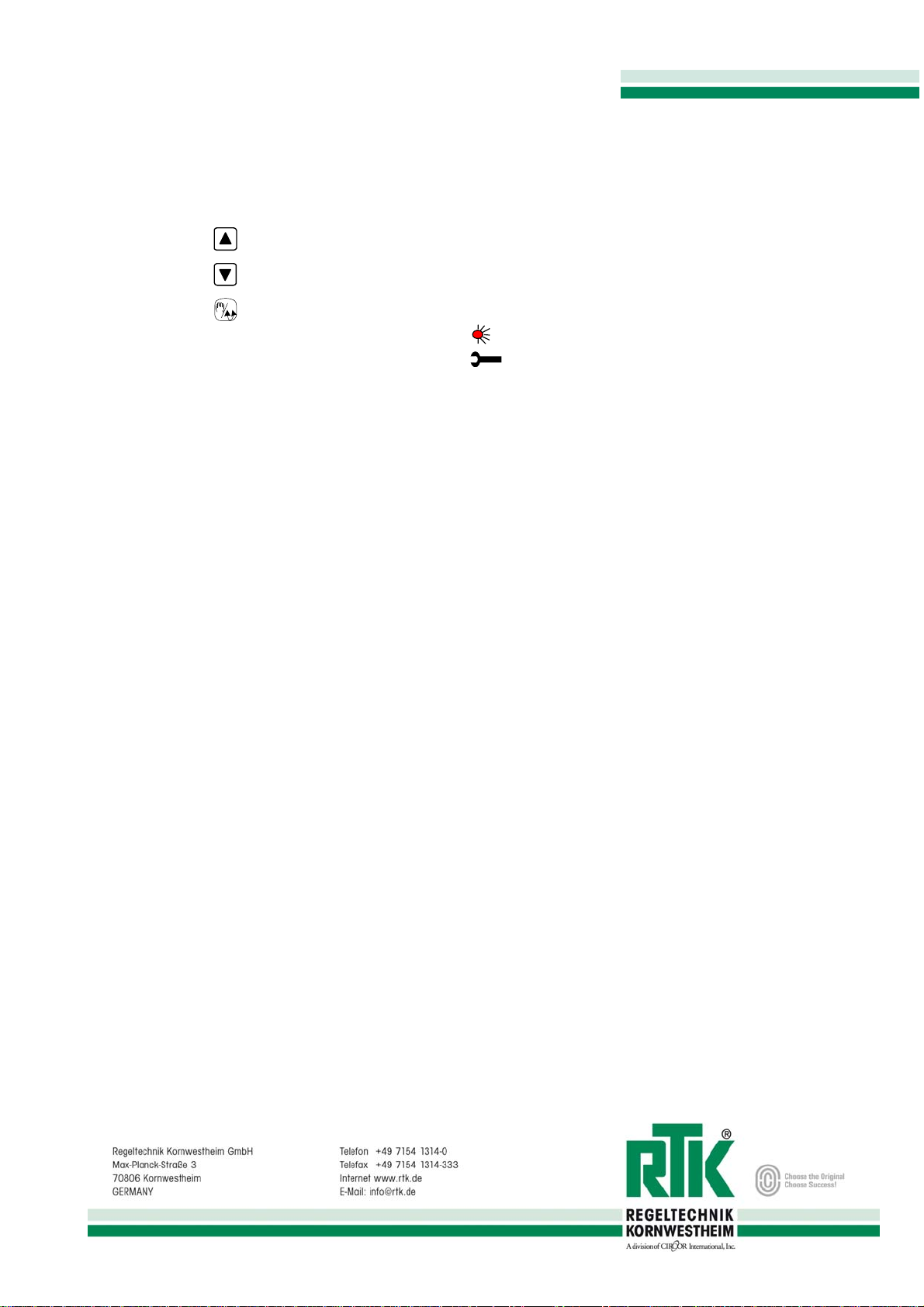
4.1 Handbetrieb
Taste drücken LED leuchtet Betriebsart: „Handbetrieb“
Stellschritte nur über Tasten am RE 3581 möglich. Alle anderen Eingänge abgeschaltet.
4.2 Automatikbetrieb
Taste drücken LED aus Betriebsart: „Automatikbetrieb“
Stellschritte nur über Führungsregler möglich
4.3 Stellungsreglerbetrieb
An Klemmen 68 und 69 Ausgang des Führungsreglers anschließen die LED 4..20mA leuchtet.
Der Hub wird durch ein 4..20mA Signal zurückgemeldet (Klemme 65 und 66). Die Rückmeldung ist galvanisch getrennt, 24V DC nötig.
4.4 Sicherheitsposition bei Signalausfall
Sollte bei Signalausfall (4..20mA) eine Sicherheitsstellung angefahren werden sind die Eingänge Z1 bis Z3 wie folgt anzuschließen:
Sicherheitsposition schließen: An Z1 und Z3 230V AC oder 24V DC je nach Ausführung anschließen
Sicherheitsposition öffnen : An Z1 und Z2 230V AC oder 24V DC anschließen
Z1 bis Z3 nicht belegt: Antrieb bleibt bei Signalausfall stehen (nur bei 4..20mA und 2..10V Ansteuerung!).
Der Regler fährt bei Signalausfall (< 2mA) in die eingestellte Position.
5Funktionsbeschreibung
Der DAC®ist ein Mikroprozessorsystem. Seine Aufgabe ist es die Befehle des Führungsreglers und ihre Auswirkungen auf den Ventilhub zu
überwachen. Bei festgestelltem Fehlverhalten, welches durch Messung der Hubstrecke kontrolliert wird, zeigt der DAC®eine entsprechende
Fehlermeldung an. Das System muß dazu einmalig initialisiert werden. Die Ventilstellung wird als 4..20mA Signal ausgegeben.
Die Endlagen (Hub 0% und Hub 100%) werden ohne Endschalter automatisch erkannt.
Der Antrieb kann durch Umschalten von Automatik auf Handbetrieb mit Hilfsenergie manuell gefahren werden.
Zusätzlich werden die Stellbefehle ausgewertet und überprüft ob sie sinnvoll sind. Wird ein periodischer Wechsel von „Öffnen -“ und
„Schließbefehlen“ festgestellt, so erkennt DAC®einen Grenzzyklus. Der Regelkreis wird durch Manipulation der Stellschritte stabilisiert.
5.1 Galvanisch getrennte Rückmeldung
Das Rückmeldesignal (4...20mA) wird auf den Hub automatisch bei der Initialisierung abgeglichen. Es ist vom Eingangssignal galvanisch
getrennt und benötigt deshalb eine externe Spannungsversorgung (12V-24V DC).
5.2 Intelligente Behandlung der Endlagen
Vor dem Erreichen der Endlagen (Hub 0% bzw. Hub 100%) schaltet der RE 3581 den Antrieb ab
Nachdem weiterhin ein Schließbefehl anliegt (ca. 5 sec.), wird der Antrieb in die Position ‚Dicht

Einbau- und Betriebsanleitung
Installation and Operating instructions
Instructions de montage et de service
3581-8010
07/2009
schließen gefahren
Der erster Stellbefehl in Gegenrichtung wird verlängert, bis der Antrieb in Regelstellung steht, also
den Ventilsitz verlassen hat
5.3 Kennlinienadaption
Ein pendelnder Antrieb wird durch Manipulation der Stellschritte stabilisiert. Das Profil erlernt der DAC®durch Adaption während des
Betriebes. Nach der Adaption wird es dauerhaft abgespeichert. Um sich zu adaptieren, muß der DAC® erkennen, in welchen
Ventilhubbereichen das Regelsystem instabil ist, und dort den Antrieb soweit manipulieren, bis die Regelung wieder stabil wird. Die
Manipulation kann allerdings nur in Grenzen durchgeführt werden.
Abbildung 1: Stellimpuls des Dreipunkt-Schrittreglers
Abbildung 2: Antrieb ohne DAC®
Abbildung 3: Adaptierter Antrieb
5.4 Drehmomentüberwachung
-Blockierung wird sofort erkannt und der Antrieb abgeschaltet
- Blockrichtung wird wieder freigegeben wenn Fahren in Gegenrichtung möglich ist
-
5.5 Stellbefehlüberwachung
-Jeder eingehende Stellbefehl wird auf seine Wirkrichtung und Auswirkung auf die Ventilstellung hin überprüft
5.6 Abgleich RE 3581
Der Regler normiert seinen Hub automatisch beim Initialisierungslauf auf das Ausgangssignal (4..20mA). Sollte das Ausgangssignal
dennoch nicht exakt mit dem Eingangssignal (4..20mA) übereinstimmen, kann ein digitaler Abgleich vorgenommen werden.
Sollte der Regler gegebenenfalls eine Endlage nicht erreichen z. B. 100%, kann das Eingangssignal ebenfalls abgeglichen werden.
Verdrahten Sie den Regler wie beschrieben. Schließen Sie am Rückmeldeausgang ein Strommeßgerät an. Schließen sie einen Stromgeber
(4..20 mA) an. Legen Sie 4 mA an. Sollte der Antrieb nicht ganz schließen oder der Rückmeldewert nicht ebenfalls 4 mA anzeigen so
gleichen Sie diesen bitte wie folgend beschrieben ab.
5.6.1 Abgleich Eingang
Um den digitalen Ableich des Eingangsignals vornehmen zu können, muß eine elektrische Verbindung (Brücke) zwischen den beiden
Punkten (siehe Abb.1) hergestellt werden.

Einbau- und Betriebsanleitung
Installation and Operating instructions
Instructions de montage et de service
3581-8010
07/2009
Abb.1:Regler ohne Deckplatte
Abgleich Eingang (Nullpunkteinstellung):
und oder
Legen Sie ein 4mA Signal am Stromeingang an und warten bis der Antrieb stehen bleibt.
Sollte die 0% Endlage nicht erreicht werden, stellen sie den Regler folgendermaßen ein
Taste Hand/Auto
gedrückt halten.
Taste "Auf" drücken Eingangssignalwert wird vergrößert => Antrieb fährt in Richtung Hub 100%
Taste "Zu" drücken Eingangssignalwert wird verkleinert => Antrieb fährt in Richtung Hub 0%
Stellen sie den Wert so ein, daß die 0% Position des Ventils übereinstimmt mit dem 0/4mA Eingangssignal. Der Antrieb muß die 0% Position
erreichen wenn 0/4 mA am Eingang anliegen.
Abgleich Eingang (Verstärkung/Bereich)
oder
Legen Sie ein 20mA Signal am Stromeingang an und warten bis der Antrieb stehen bleibt.
Sollte die 100% Endlage nicht erreicht werden, stellen sie den Regler folgendermaßen ein
Taste "Auf" drücken Eingangssignalwert wird vergrößert => Antrieb fährt in Richtung Hub 100%
Taste "Zu" drücken Eingangssignalwert wird verkleinert => Antrieb fährt in Richtung Hub 0%
Stellen sie den Wert so ein, daß die 100% Position des Ventils übereinstimmend erreicht wird mit dem 20mA Signal am Stromeingang.
Kontrollieren Sie die 0% Endlage nochmals, den Abgleich eventuell wiederholen.
Trennen sie die Verbindung (Brücke) wird der Abgleich dauerhaft gespeichert LED "Service" erlischt
5.6.2 Abgleich 4..20mA Ausgang
Um den digitalen Abgleich des Rückmeldesignal vornehmen zu können muß eine elektrische Verbindung (Brücke) zwischen den beiden
Punkten (siehe Abb.2) hergestellt werden LED "Service" leuchtet.
Abb.2:Regler ohne Deckplatte
Abgleich Zero (Nullpunkteinstellung):
und oder
Legen Sie 4 mA am Stromeingang an und warten bis der Antrieb die 0% Endlage erreicht hat.
Taste Hand/Auto
gedrückt halten.

Einbau- und Betriebsanleitung
Installation and Operating instructions
Instructions de montage et de service
3581-8010
07/2009
Taste "Auf" drücken Rückmeldewert wird größer
Taste "Zu" drücken Rückmeldewert wird kleiner
Stellen Sie genau 4 mA ein.
Abgleich Span (Verstärkung/Bereich)
oder
Legen Sie 20 mA am Stromeingang an und warten bis der Antrieb die 100% Endlage erreicht hat.
Taste "Auf" drücken Rückmeldewert wird größer
Taste "Zu" drücken Rückmeldewert wird kleiner
Stellen Sie genau 20 mA ein.
Kontrollieren Sie den 0% Endwert nochmals, den Abgleich eventuell wiederholen.
Trennen sie die Verbindung (Brücke), wird der Abgleich dauerhaft gespeichert, die LED "Service" erlischt.
6Fehlermeldungen
6.1 Blockierung in Schließrichtung
4..20mA
6.2 Blockierung in Aufrichtung
4..20mA
6.3 Schwerwiegender Fehler
4..20mA
6.4 Potentialfreier Störmeldeausgang
- Der potentialfreie Störmeldeausgang kann mit 5V bis 48 V DC versorgt werden.
- Im Normalbetrieb ist der Ausgang low (aktive) (<0,3V) geschaltet.
- Bei Störung ist der Ausgang auf high (5V bis 48 V DC) geschaltet und signalisiert so jede Störung
Bei Fehlermeldungen Ursache beseitigen!
Der Antrieb blockierte beim Schließen.
Die LED`s BLOCK und ZU blinken invers.
Der Fehler wird gelöscht sobald in Gegenrichtung gefahren wird.
Der Antrieb blockierte beim Öffnen
Die LED`s BLOCK und AUF blinken invers
Der Fehler wird gelöscht sobald in Gegenrichtung gefahren wird.
Das Ventil kann in keine Richtung mehr bewegt werden.
Die LED INIT blinkt, Paßwort wird verlangt.
Neue Initalisierung erforderlich!

Einbau- und Betriebsanleitung
Installation and Operating instructions
Instructions de montage et de service
3581-8010
07/2009
1General Information
The digital positioner RE 3581 DAC®is a microprocessor system which drive the actuator from 0% to 100% with an input signal from
4..20mA. The controller needs a potentiometer feedback about the whole stroke of the actuator. An internal measurement transducer
transmit the potentiometer signal into a 4..20mA feedback signal, which is potential free from the input signal. The adjustment plays
automatically during the initialisation. A digital adjustment after the initialisation can be done with the keys on the RE3581. It drives the
actuator with relays. Every Step will be controlled and errors will be detect from the RE 3581.
Caution: Before beginning to install or operate valves, please read the pamphlet "Hazard Warning...", the instructions for the actuator and, if
applicable, those for the optional devices.
Only trained and qualified specialist staff may install and commission valves
2Installation and connection
The controller is wired and supplied with factory settings. If the controller is delivered in actuator with valve, it is working after connecting in
your system. Otherwise see the following setting instructions.
After mounting the controller into the actuator do the following:
Connect the motor, potentiometer, input signal and output signal as described in Cap. 2.1 wiring diagram. The potentiometer must be
adjusted that if the valve is closed, the value of the potentiometer is nearly 10% of the whole Potentiometer value. You can measure the
potentiometer value between Terminal 62 and 63. If the valve is completely opened, the value should be nearly 90% of the whole
Potentiometer value.
Normal operation of the controller:
Control valve in 2 way design: 0% stroke (valve closed) potentiometer ca. 10% of its value output 4mA
100% stroke (valve opened) potentiometer ca. 90% of its value output 20mA
Control valve in 2 way design: 0% stroke (B closed) potentiometer ca. 10% of its value output 4mA
100% Hub (B opened potentiometer ca. 90% of its value output 20mA
To change the operating direction, changethe wires on terminal 61 with terminal 63 and terminal K5 with K6.
2.1 Wiring diagram
Appendix
3Setting in motion
The setting in motion is only possible if the mounting is correct as in cap. 2.1 Wiring diagram described.
If it is delivered with an actuator and valve, the controller is correct mounted. A new initialisation is not necessary.
The controller works correct.
By mounting in a actuator or changing the controller or the potentiometer, a new initialisation is necessary.
To initialisation the controller the LED must be flashing. To make it flashing see cap. 3.1 delete Initialisation data (Reset)

Einbau- und Betriebsanleitung
Installation and Operating instructions
Instructions de montage et de service
3581-8010
07/2009
3.1 Delete initialisation data (Reset)
Before you can make a new initialisation, you have to delete the present data.
Deleting the present data:
Press all 3 keys together longer than 10 sec. (All LEDs are lighting).
After all LEDs was lighting for 2 sec. the service LED is flashing . The controller is waiting for password input, to start the automatic
initialisation.
3.2 Initialisation
The following things must be done exactly for a correct initialisation.
1. Control potentiometer and if its possible adjust it as described.
2. Switch manual mode on (see cap. 4.1 manual operation)
3. Enter password
4. Drive valve to middle position (+/- 20%).
5. Switch manual mode off, initialisation starts automatically.
6. After the initialisation is finished (1-3 minutes, depends on stroke and motor speed) switch power off and on again. The controller is
switched now in manual mode. If this happens the data was saved correct. Switch to automatic mode and the initialisation is complete.
The RE 3581 is now ready for work!
3.3 non-monitored manual operation
After entering the correct password, the valve can be operated via the keys "OPEN" and "CLOSE". Drive the valve to the middle position
+/- 20%. It is not possible to start the initialisation nearly the end positions.

Einbau- und Betriebsanleitung
Installation and Operating instructions
Instructions de montage et de service
3581-8010
07/2009
3.4 Function diagram of the initialisation
Press all 3 buttons as long as all lights are on.
After a few seconds is flashing
RE 3581
in operation
Initialisation
ok?
yes
Drive valve to middle
position +/-20% with
and keys
Handmode off
start initialisation
automatic
initialisation plays
Enter password
(see bottom)
password ok?
yes
off
no
no
Attention:
At 2-way valves you
must limit stroke 100%
by
Manual stroke limitation
push
stroke 100% set
All LEDs 3 sec. on
4..20mA
All LEDs 3 Sec. on
4..20mA
push
stroke 0% set
Measurement
Password:
All LEDs 3 sec. on
4..20mA
push on
on
non-monitored
manual mode on

Einbau- und Betriebsanleitung
Installation and Operating instructions
Instructions de montage et de service
3581-8010
07/2009
4Description of Function
The controller is working in 4 different Functions.
4.1 Manual operation
Press key the LED is lighting manual operation is switched on. Driving the valve only with the keys on the RE3581
possible. Other input signals are switched off.
4.2 Automatic operation
Press key the LED is not lighting automatic operation is switched on. Driving the valve only with the input signals on the
RE3581 possible.
4.3 Positioner operation
At terminal 68 and 69 connect the output signal of the master controller, LED 4..20mA lighting.
The feedback of the stroke is also a 4..20mA signal (Terminal 65 and 66). It is galvanic isolated, so a 24V DC power supply is needed.
4.4 Safety position when interrupted input signal
If the input signal (4..20mA) breaks you can appear a safety position with connecting the power supply at Z1 to Z3:
safety position closed: connect at Z1 and Z3 230V AC optional 24V DC
safety position opened : connect at Z1 and Z2 230V AC optional 24V DC
Z1 to Z3 not connected: actuator do nothing when signal is broken (only at 4..20mA and 2..10V input signal).
If the input signal gets lower than 2mA or 1V the controller drives in safety position.
5Setting in motion
DAC is a microcontroller system. Its job is to monitor the result of the commands of the controller. If any error occurs, which is recognised by
measurement of the stroke, an error indication is displayed. An initialisation for the first time is need to get the RE 3581 in operation. The
stroke limits 0% and 100% are recognised without limit switches. The RE 3581 is generating a feedback signal (4..20mA) for the stroke.
Manual operation is possible during power supply on.
5.1 Galvanic isolated feedback
The stroke of the valve is automatically recognised and generated to a galvanic isolated feedback signal (4...20mA). The feedback signal
needs a power supply of 12-24 V DC. (see cap.2.1 "Wiring diagram")
5.2 Intelligent limit switches
When the actuator reaches the limits (stroke 0% or 100%) RE 3581 switches off. After reaching the close position, it waits for 5 secs before
driving the actuator to "closing tight". The first step in the other direction is lengthened, until the actuator is in controlling position.
5.3 Charakteristic adaption
An oscillating actuator is stabilised by correcting the command attributes. The profile is learned during operation and saved permanently.
For adapting purposes, DAC needs
1. to recognise in which stroke range the control loop is unstable
2. to stabilise the control loop by correcting the command attributes.
Picture 1: Steps of the controller
Picture 2: Actuator without DAC6

Einbau- und Betriebsanleitung
Installation and Operating instructions
Instructions de montage et de service
3581-8010
07/2009
Picture 3: Adapted actuator
5.4 Torque control
Valve blockages are immediately recognised and the actuator is stopped.
After the next step in the other direction, the actuator is allowed to reverse.
5.5 Command control
Every step of the direction of the valve spindle and the result is checked.
5.6 Adjustment RE 3581
The controller calculate the feedback signal at the initialisation automatically and generates an output signal (4..20mA). If this signal is not
exactly correct, you can adjust it:
You can also adjust the input signal for example if an end position can not be reached.
Wire the controller as described. Connect a mA multimeter at terminals 65 and 66. Connect a 4 mA signal to the input. If the valve is not
closing tight after 5 s or if the feedback signal is not correct
5.6.1 Adjustment input
For entering the input signal correction program you must connect these two pins on the top of the controller (see picture 1). The "Service-
LED" is on.
picture1: Controller RE3581 without front panel
Adjust zero (Input signal):
and or
connect 4mA signal e.g. to the input and wait (min. 5 sec.) as the controller stopped. Control the valve position. If the position is not
correct, make a digital correction:
key hand/auto keep pressed
step with key "Open" to make the input signal higher
step with key "Close" to make the input signal lower
adjust the signal exactly at the right valve position.
Adjust span (Input signal):
or
connect 20mA signal to the input and wait as long as the controller stopped. Control the valve position. If the position is not correct,
make a digital correction:

Einbau- und Betriebsanleitung
Installation and Operating instructions
Instructions de montage et de service
3581-8010
07/2009
step with key "Open" to make the input signal higher
step with key "Close" to make the input signal lower
Now control the limit position again!
Control both values again, to be sure it is correct.
Disconnect the bridge and the data will be saved.
6.5.2 Adjustment output 4..20 mA
For entering the input signal correction program you must connect these two pins on the top of the controller (see picture 2). The "Service-
LED" is on.
picture 2: Controller RE3581 without front panel
Adjust zero (Output signal):
and or
connect 4mA signal e.g. to the input and wait (min. 5 sec.) as the controller stopped. Control the valve position. If the feedback
signal is not correct, make a digital correction:
key hand/auto keep pressed
step with key "Open" to make the output signal higher
step with key "Close" to make the output signal lower
adjust the signal exactly at the right output value.
Adjust span (Output signal):
or
connect 20mA signal to the input and wait as long as the controller stopped. Control the valve position. If the position is not correct,
make a digital correction:
step with key "Open" to make the input signal higher
step with key "Close" to make the input signal lower
Now control the limit position again!
Control both values again, to be sure it is correct.
Disconnect the bridge and the data will be saved.
3581

Einbau- und Betriebsanleitung
Installation and Operating instructions
Instructions de montage et de service
3581-8010
07/2009
6Error codes
6.1 Blockage in closing direction
4..20mA
6.2 Blockage in Opening Direction
4..20mA
6.3 Fatal error
4..20mA
6.4 Potential free alarm output
- The potential free alarm output operate with 5V up to 48 V DC supply.
- It is operating low active (<0,3V).
- If there is any error on the system the output will be switched to high Voltage signal.
If any error occurs, correct the source of the problem.!
Actuator was blocked during closing.
LEDs Blockage and Close are flashing alternately.
Flashing indications disappears with the next step in the other
direction
Actuator was blocked during opening
LEDs Blockage and Open are flashing alternately.
Flashing indications disappears with the next step in the other
direction
The valve cannot be moved any more. The Led INIT is flashing, DAC
is waiting for a password. A new initialisation is required.

Einbau- und Betriebsanleitung
Installation and Operating instructions
Instructions de montage et de service
3581-8010
07/2009
1Informations générales
Le positionneur numérique RE 3581 règle la position de l'actionneur en fonction du signal d'entrée appliqué. Pour ce faire, il a besoin d'un signal de compte
rendu potentiométrique, couvrant l'intégralité de la course de l'actionneur. Il est doté d'un transmetteur de mesure intégré convertissant le signal du
potentiomètre en un signal de sortie continu 4..20mA. Le RE 3581 compare le signal d'entrée à la position du potentiomètre et commande la position de
l'actionneur à travers un étage à relais. L'adaptation du potentiomètre est effectuée automatiquement au cours de l'initialisation et peut être, le cas échéant,
ajustée numériquementau clavier.
Attention! : Avant de procéder au montage ou à l'exploitation d'équipements de régulation électrique, veuillez lire attentivement le
document "Avertissement des risques...".
Seules les personnes qualifiées disposant d'une formation sont autorisées à procéder au montage et à la mise en
service.
1.1 Touches et LED’s
2Montage et raccordement
Le positionneur est intégré à l'actionneur et câblé en usine. Lorsque le positionneur est livré monté dans un actionneur avec
vanne, il est déjà réglé et, par conséquent, prêt à fonctionner.
En cas de montage ultérieur du positionneur, respectez les instructions suivantes :
En cas de montage ultérieur, raccordez le moteur, le potentiomètre et les signaux d'entrée et de compte rendu de position conformément
aux instructions du appendix raccordement électrque. Le potentiomètre doit être ajusté de telle sorte que lorsque la vanne est fermée
(course 0%), on mesure environ 10% de la valeur ohmique entre les bornes 62 et 63. Lorsque la vanne est ouverte, on doit atteindre environ
90% de la valeur ohmique. En cas d'inversion du sens d'action, ces valeurs sont à mesurer entre les bornes 61 et 62. Avec un potentiomètre
sans butée, il faut veiller à ne pas dépasser le zéro.
Les valeurs d'ajustage sont les suivantes :
pour les vannes droites : 0% de la course (vanne fermée) potentiomètre env. 10% de la valeur sortie 4 mA
100% de la course (vanne ouverte) potentiomètre env. 90% de la valeur sortie 20 mA
pour les vannes 3 voies :0% de la course (voie B fermée) potentiomètre env. 10% de la valeur sortie 4 mA
100% de la course (voie B ouverte) potentiomètre env. 90% de la valeur sortie 20 mA
En cas de commande inversée, échangez les bornes 63 et K6 respectivement contre les bornes 61 et K5.
Hand / Automatik
Umschaltung
Man / Auto
Mode manuel / mode automatique
A
ntriebsspindel
Ausfahren Ventil schließen
Valve close
Vanne fermer
A
ntriebsspindel einfahren
Ventil öffnen
Valve open
Vanne ouvir
Betrieb
Operation
Fonctionner 4..20mA
Stellungsregler
Positioner
Positioneur
Öffnen
Opening
Ouvir
Schließen
Closing
Fermer
Handbetrieb
Manual mode
Manuel
Endlage
End position
Service
Service
Service

Einbau- und Betriebsanleitung
Installation and Operating instructions
Instructions de montage et de service
3581-8010
07/2009
2.1 Raccordement électrique
Voir annexe.
3Mise en service
Ne procéder à la mise en service qu'après avoir effectué le raccordement électrique conformément aux instructions du appendix
raccordement électrique.
En cas de livraison avec la vanne, le positionneur est réglé en usine. Il n'est pas nécessaire de l'adapter à la course de la vanne.
Le positionneur est prêt à fonctionner.
En cas de montage ultérieur ou de remplacement du positionneur ou d'échange du potentiomètre, il faut procéder à une initialisation, c'est-
à-dire une adaptation à la course de la vanne.
Pour pouvoir réinitialiser le positionneur, il faut que la LED clignote, voir le chapitre 3.1 Effacement des données d'initialisation (reset)
3.1 Effacement des données d'initialisation (reset)
Pour pouvoir réinitialiser le positionneur, vous devez d'abord effacer les données d'initialisation actuelles.
Effacement des données actuelles :
enfoncez simultanément les 3 touches pendant plus de 10s
(jusqu'à ce que toutes les LED soient allumées).
Après que toutes les LED soient restées allumées pendant env. 2 s, la LED clignote. Le positionneur attend l'introduction d'un mot de
passe pour démarrer l'initialisation.
3.2 Initialisation
Les étapes suivantes sont nécessaires à l'initialisation et doivent être respectées exactement :
1. contrôlez le potentiomètre comme décrit plus haut, le cas échéant, l'ajuster,
2. activez le mode manuel (voir chap. 4.1 Mode manuel),
3. entrez le mot de passe (voir chap. 3.4 Schéma séquentiel de l'initialisation),
4. amenez la vanne en position médiane (+/- 20%),
5. désactivez le mode manuel, l'initialisation démarre automatiquement.
3.3 Mode manuel sans surveillance
Une fois le mot de passe correct entré, vous pouvez manœuvrer la vanne en mode manuel à l'aide des touches "Ouvrir" et "Fermer".
Amenez la vanne en position médiane +/- 20%. Il ne faut en aucun cas lancer l'initialisation lorsque la vanne est près d'une des positions de
fin de course.

Einbau- und Betriebsanleitung
Installation and Operating instructions
Instructions de montage et de service
3581-8010
07/2009

Einbau- und Betriebsanleitung
Installation and Operating instructions
Instructions de montage et de service
3581-8010
07/2009
3.4 Schéma séquentiel de l'initialisation
RE 3446
prêt
Initialisation
o.k.?
oui
Amenez vane en position
médiane +/-20%
Touches et
Mode manuel
désactivé
Démarre initialisation
Initialisation
automatique en cours
Entz mot de passe
(voir ci-dessous)
Passwort ok?
oui
éteint
non
non
Mise en garde.
Pour des vannes 2 voies
la position de course
maximale (100 %) doit être
réglée à la main.
Limitation manuellede
Enfoncez
Définir course 100%
4..20mA
4..20mA
Enfoncez
Définir course 0%
Mesure actionneur
Mote de passe:
max. 10s
LED allumées 3 s
4..20mA
Enfoncez allumé
allumé
mode manuel
non surveillé actif
Enfoncez simultanément les 3
Quand clignote, données d'initialisation effacées

Einbau- und Betriebsanleitung
Installation and Operating instructions
Instructions de montage et de service
3581-8010
07/2009
4Modes de fonctionnement
Le positionneur fonctionne avec 4 modes de fonctionnement distincts.
4.1 Mode manuel
Enfoncez la touche ; la LED s'allume, mode de fonctionnement "manuel" activé.
Commande de la vanne possible uniquement avec les touches du RE 3581. Toutes les autres entrées sont désactivées.
4.2 Mode automatique
Enfoncez la touche ; la LED s'éteint, mode de fonctionnement "automatique" activé.
Commande de la vanne possible uniquement par un régulateur pilote.
4.3 Mode positionneur
Connectez la sortie du régulateur pilote aux bornes 68 et 69; la LED 4..20mA s'allume.
La course est signalée en retour par un signal 4..20mA (bornes 65 et 66). Le signal de compte rendu est séparé galvaniquement; une
alimentation 24V DC est nécessaire.
4.4 Position de sécurité en cas de défaut du signal
Vous pouvez rallier une position de sécurité en cas de défaut du signal (4..20mA) en connectant les entrées Z1 à Z3 de la manière suivante
:
position de sécurité fermée : connectez 230V AC ou 24V DC, selon l'exécution, à Z1 et Z3
position de sécurité ouverte : connectez 230V AC ou 24V DC, selon l'exécution, à Z1 et Z2
Z1 à Z3 non connectés : l'actionneur s'arrête en cas de défaut du signal (uniquement commande 4..20mA et 2..10V!).
En cas de défaut du signal (< 2mA), le positionneur rallie la position configurée.
5Description fonctionnelle
Le DAC®est un système à microprocesseur. Son rôle est de contrôler les commandes de l’organe directeur et leur effet sur la
course de la soupape. Lorsqu’il détecte un dysfonctionnement, en mesurant la course, le DAC®affiche un message d’erreur
correspondant. Le système doit alors être réinitialisé une fois. La position de la soupape est donnée sous forme d’un signal de
4..20 mA.
Les fins de course (course 0 % et course 100 %) sont reconnues automatiquement sans l’intervention d’un interrupteur.
L’entraînement peut être démarré manuellement sur courant de secours en passant du mode automatique au mode manuel.
Par ailleurs, les commandes de positionnement sont évaluées pour vérifier leur pertinence. La détection d’une variation
périodique entre commandes « d’ouverture » et de « fermeture » permet au DAC®de reconnaître un cycle limite. Le circuit de
régulation peut être stabilisé en modifiant les pas de réglage.
5.1 Signal de compte rendu de position avec séparation galvanique
Le signal de compte rendu de position (4...20mA) est ajusté automatiquement à la course au cours de l'initialisation. Il est séparé
galvaniquement du signal d'entrée, et nécessite par conséquent une alimentation en tension externe (12V-24V DC).
5.2 Traitement intelligent des positions de fin de course
Le RE 3581 coupe l'actionneur avant que la position de fin de course ( 0% ou 100%) ne soit atteinte.
Si l'ordre de fermeture est maintenu (pendant env. 5 s), l'actionneur est manoeuvré à la position de fermeture étanche.
Le premier ordre de positionnement en sens inverse est prolongé jusqu'à que l'actionneur soit en position de réglage, c'est-à-dire qu'il ne
soit plus en contact avec le siège de la vanne.
Table of contents
Languages:
Other RTK Valve Positioner manuals
Popular Valve Positioner manuals by other brands

ABB
ABB TZIDC manual

rotork
rotork YT-3700 product manual

Flowserve
Flowserve XL90 Series Installation, operation & maintenance instructions

Flowserve
Flowserve APEX 8000 Series Installation operation & maintenance

ABB
ABB TZIDC manual

INDELAC CONTROLS
INDELAC CONTROLS 22018-DH Installation, operation & maintenance manual