manuals.online logo
Brands
  1. Home
  2. •
  3. Brands
  4. •
  5. Fisher
  6. •
  7. Controllers
  8. •
  9. Fisher 670F User manual

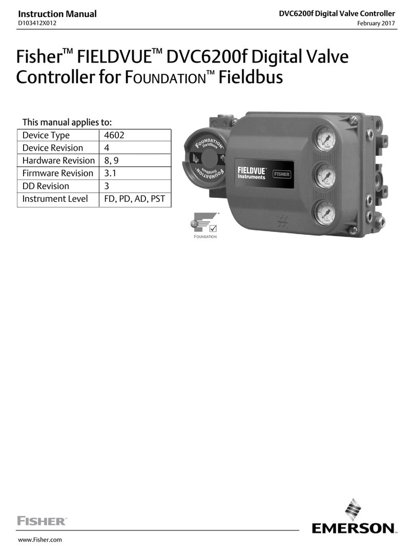
Fisher 670F User manual

D200109X012
67
0 S
erie
s P
anel-Mounte
d L
oadin
g R
egulator
Assemblies
WARNING
Fisher regulators should be installed,
operated, and maintained in accordance
with federal, state, and local codes,
rules and regulations, and Fisher In-
structions.
If a leak develops in the system, it indi-
cates that service is required. Failure to
take the regulator out of service immedi-
ately may create a hazardous condition.
Call a gas serviceman in case of trouble.
Only a qualified person must install or
service the regulator.
Introduction
The 670 Series panel-mounted loading regulator as-
semblies are used primarily for manually controlling
pressure to diaphragm control valves or as remote
pressure loaders for pressure-balanced gas regula-
tors. They are also widely used for remote control of
gas pressure to burners in refinery tube stills, power
plants, and similar process furnaces.
Installation
Inspect the panel after it is removed from its packing.
Connect a 1/4-inch pipe line from the operating supply
pressure to the connection marked “IN” on the pres-
sure regulator.
One and two-gauge panels: Connect a line to the dia-
phragm casing of the main valve or regulator and run it
to the connection marked “OUT” on the panel regula-
tor. When installing a two-gauge panel, connect a line
Figure
1. Typical 670 Series Regulator; Two-Gauge
Panel with Three-Way Changeover Valve
W0554-1/IL
from the control pressure line to the upper diaphragm
casing and to the control pressure gauge (instrument
loading pressure) in the back of the panel (see figure
2).
Two-gauge panel with a three-way changeover valve:
Connect the air supply, diaphragm connection, and
instrument loading pressure line to the panel regulator
as shown in figure 4.
Start-Up
Open the air supply line. Check all connections for
leaks. The manual loading pressure gauge indicates
the loading pressure on the diaphragm of the main
valve. To increase the loading pressure, turn the hand-
wheel clockwise. To decrease the loading pressure,
turn the handwheel counterclockwise.
Instruction Manual
Form 965
July 1987 670 Series
670 Series
2
Table 1. T
ype Number Description
Type Number Number of
Gauges Description Regulator
Type Number Maximum
Inlet Pressure
Maximum
Outlet
Pressure
Maximum
Emergency
Outlet
Pressure
670 1 Basic 1-gauge panel 67R
670F 1 1-gauge panel; regulator has filter 67AFR 250 Psig 100 Psig 110 Psig
670FG 2 2-gauge panel; regulator has filter 67AFR
250
Psig
100
Psig
110
Psig
670FGV 2 2-gauge panel with 3-way changeover
valve; regulator has filter 67AFR 50 Psig 50 Psig 55 Psig
670G 2 Basic 2-gauge panel 67R 250 Psig 100 Psig 110 Psig
670GV 2 2-gauge panel with 3-way or 4-way
changeover valve 67R 50 Psig 50 Psig 55 Psig
671 1 Basic 1-gauge panel 912N 250 Psig 5 Psig 10 Psig
672V 1 Basic 1-gauge panel with 3-way
changeover valve ––– ––– ––– –––
675 2 Basic 2-gauge panel 67R 250 Psig 100 Psig 110 Psig
Units with a three-way changeover valve may be
placed under manual operation. When changing from
manual to automatic or from automatic to manual con-
trol, set the manual control pressure gauge to read the
same as the instrument pressure in order to prevent
bumping.
Overpressure Protection
WARNING
Overpressuring any portion of this
equipment may cause damage to regula-
tor parts, leaks in the regulator, or per-
sonal injury due to bursting of pressure-
containing parts or explosion of
accumulated gas.
To avoid overpressure, provide ap-
propriate overpressure protection to en-
sure that none of the pressure limits will
be exceeded.
The regulator assembly should be in-
spected for damage after any overpres-
sure condition.
As is the case with most regulators, regulators in the
670 Series have outlet pressure ratings which are low-
er than the inlet pressure ratings. Overpressure
protection is needed if the actual inlet pressure can
exceed the outlet pressure rating. A common method
of overpressure protection is a relief valve.
Maximum emergency outlet pressure ratings are
shown in table 1 for each loading regulator.
Principle of Operation
The 670 Series regulators are set manually to control
supply pressure to diaphragm control valves or gas
regulators. Instrument and manual loading pressures
are read from the pressure gauges of the regulator. If
pressure to the valve needs to be adjusted, the regula-
tor handwheel is turned clockwise to increase the sup-
ply pressure or counterclockwise to decrease the sup-
ply pressure.
Maintenance
The regulator can be removed from the panel to be
disassembled. Take out the set screws or loosen the
hex nut to remove the regulator from the panel. Refer
to the appropriate instruction manual for further main-
tenance on the regulator.
Serial Number
When corresponding with your Fisher representative
about this equipment, be sure to include the serial
number that is stamped on the nameplate on the back
of the panel. Include the complete eleven-character
part numbers from the following Parts List when order-
ing new parts.
Parts
List
Key Description Part Number
1 Regulator—Part numbers for the regulators
used in the 670 Series are shown in the
regulator instruction manuals
670 Series
3
Figure
2. Typical Installation of a Type 670 Regulator
Figure 3. Type 671 Regulator Assembly Drawing
Figure 4. Type 670GV Regulator Assembly Drawing
DC2668-D
A1728-1/IL
AF5052-C/DOC
30A6617-B/DOC
670 Series
4
Key Description Part Number
2 Gauge
0-5 psig 23A8325 X012
0-15 psig
2C2332 000B2
0-30 psig
2C2332 000C2
0-60 psig
2C2332 000D2
0-100 psig
2C2332 000E2
0-160 psig
2C2332 X0022
0-200 psig
2C2332 000F2
0-300 psig 2C2332 X00A2
0-400 psig
2C2332 X0032
0-600 psig
2C2332 X0042
0-60 psig & 0-4 kg/cm2
1R7662 99012
0-60-200 psig & 0-4-14 kc/cm2
1R7663 99012
3 Panel
Types 670 & 670F, zinc
1C2333 44012
Type 670FG, steel
3E6607 25132
Type 670G, steel
3J8460 25132
Types 670GV & 670FGV (3-way valve), steel
3E6608 25132
Type 671, zinc
1C2337 44012
Type 672V, zinc
1C7812 44012
Type 675G, steel
3H1843 25132
4 Clamp Bar, cd pl steel (4 req’d)
1C2338 24162
5 Hex Nut, cd pl steel
Types 670, 670F, 670FG, 670FGV, 671,
& 675G (4 req’d)
1E9853 24142
Types 670G, 670GV, & 672V
(6 req’d)
1E9853 24142
6 Machine Screw, steel (4 req’d)
1C2339 28992
7 Tubing, copper
Type 670 19A1553 X012
Type 670F 19A1562 X012
Type 670FG 19A1564 X012
Type 670FGV 19A1565 X012
Type 670G 19A1569 X012
Type 670GV 19A1556 X012
Type 671 19A1511 X012
Type 672V 19A1572 X012
Type 675G 19A1573 X012
8 Fitting, brass
Types 670, 670F, & 671 15A6002 X272
All other types 15A6002 X262
9 Fitting, brass
Types 670, 670F, & 672V
1C6197 18992
Type 670FG 15A6002 X172
Types 670FGV & 670GV (3 req’d) 15A6002 X172
Type 670G 15A6002 X212
Type 671 15A6002 XA92
Type 675G (2 req’d)
1C6197 18992
10 Nipple
Types 670, 670F, & 670G, brass
1B6782 18992
Types 670FGV, 670GV, & 675G, brass
(2 req’d)
1B6782 18992
Type 671, steel
1H3929 26012
Key Description Part Number
11 Fitting, brass
Types 670 & 672V 15A6002 X212
Type 670F 15A6002 X382
Type 670FG
1L4720 18992
Types 670FGV, 670G, & 670GV
(2 req’d)
1C6197 18992
Type 671
1D5016 21992
Type 675G (2 req’d) 15A6002 X212
12 Tubing, copper
Type 670GV 19A1560 X012
Type 675G 19A1574 X012
13 Changeover Valve
Types 670FGV, 670GV, & 672V (2-way
or 3-way)
1C2695 18992
15 Gauge Service Marking(1)
Types 670, 670F, 671, & 672V
1C5386 06092
Type 670FG (one of each)
1C5386 06092
1C5387 06092
Type 670FGV (one of each)
1L3355 06092
1L3356 06092
Types 670G & 670GV (one of each)
1C5386 06092
14A2561 X012
Type 675G (2 req’d)
1C5386 06092
16 Machine Screw, pl steel
Types 670FGV, 670GV, & 672V (2 req’d)
1C2703 28992
17 Fitting, brass
Type 670G
1C2698 18992
Types 670GV & 670FGV (2 req’d)
1C2698 18992
18 Valve Dial, plastic
Type 670FGV (3-way valve)
1L3511 06992
Type 670GV (2-way valve)
1D6367 X0021
Type 670GV (3-way valve)
1C2696 06092
Type 672V (3-way valve)
1C7814 06992
19 Machine Screw, steel
Types 670, 670F, & 671 (2 req’d)
1C2704 28992
Types 670FG, 670G, 672V, & 675G (4 req’d)
1C2704 28992
Types 670FGV & 670GV (6 req’d)
1C2704 28992
20 Tubing, copper
Types 670FGV & 670GV (2 req’d) 19A1558 X012
23 Support Post, brass
Types 670FGV, 670GV, & 672V (2 req’d) (Not
shown)
1C2697 14012
24 Bleed Orifice & Screen Ass’y, brass/Monel
Types 670, 670F, 670FG, 670FGV, & 670GV 1K8845 X0012
Type 671
1D5015 X0012
Type 675G (2 req’d) 1K8843 X0012
25 Serial Plate, aluminum
1C5840 11992
26 Hex Nut, pl steel
Type 670FG (4 req’d)
1A3303 28982
All other types (2 req’d)
1A3303 28982
27 Fitting
Type 671, malleable iron
1D5017 21992
Type 670FGV & 670GV, brass 15A6002 X212
28 Fitting, brass
Types 670FGV, 670G, & 670GV 15A6002 X272
33 Mounting Post, steel (3 req’d) (not shown) 1F2449 X0012
1. A plate may be engraved with any service marking or terminology. Letter height is 1/8 inches
(3.2 mm). There is space for 3 lines with up to 16 letters per line.
For information, contact Fisher Controls:
Marshalltown, Iowa 50158 USA
Cernay 68700 France
Sao Paulo 05424 Brazil
Singapore 128461
                                
                                 
Printed in U.S.A.
Fisher Controls International, Inc. 1987; All Rights Reserved
Fisher, Fisher-Rosemount, and Managing The Process Better are marks owned by Fisher Controls International, Inc. or Fisher-Rosemount Systems, Inc.
All other marks are the property of their respective owners.
This manual suits for next models

8

Other Fisher Controllers manuals

Fisher 657 User manual

Fisher

Fisher 657 User manual

Fisher 4194B Series User manual

Fisher

Fisher 4194B Series User manual

Fisher R622 User manual

Fisher

Fisher R622 User manual

Fisher EZR Series User manual

Fisher

Fisher EZR Series User manual

Fisher FIELDVUE DLC3010 User manual

Fisher

Fisher FIELDVUE DLC3010 User manual

Fisher DPR900 User manual

Fisher

Fisher DPR900 User manual

Fisher Fieldvue DVC5010 User manual

Fisher

Fisher Fieldvue DVC5010 User manual

Fisher 667 User manual

Fisher

Fisher 667 User manual

Fisher FIELDVUE DVC6200 HW1 User manual

Fisher

Fisher FIELDVUE DVC6200 HW1 User manual

Fisher 480 User manual

Fisher

Fisher 480 User manual

Fisher 1290 User manual

Fisher

Fisher 1290 User manual

Fisher 1051 User manual

Fisher

Fisher 1051 User manual

Fisher 4660 User manual

Fisher

Fisher 4660 User manual

Fisher 4195 KB Series User manual

Fisher

Fisher 4195 KB Series User manual

Fisher 656 User manual

Fisher

Fisher 656 User manual

Fisher 67CF User manual

Fisher

Fisher 67CF User manual

Fisher 685 User manual

Fisher

Fisher 685 User manual

Fisher 6492HTM User manual

Fisher

Fisher 6492HTM User manual

Fisher 1061 User manual

Fisher

Fisher 1061 User manual

Fisher 1066 User manual

Fisher

Fisher 1066 User manual

Fisher FIELDVUE DVC6200 Configuration guide

Fisher

Fisher FIELDVUE DVC6200 Configuration guide

Fisher 3570 User manual

Fisher

Fisher 3570 User manual

Fisher 1052PSV User manual

Fisher

Fisher 1052PSV User manual

Fisher L2e User manual

Fisher

Fisher L2e User manual

Popular Controllers manuals by other brands

dixell XR70CX Installing and operating instructions

dixell

dixell XR70CX Installing and operating instructions

LRP electronic FLOW X installation manual

LRP electronic

LRP electronic FLOW X installation manual

Danfoss AK-PC 781A user guide

Danfoss

Danfoss AK-PC 781A user guide

Alemite 7936 Service guide

Alemite

Alemite 7936 Service guide

Spirax Sarco PN9400E Series Technical data

Spirax Sarco

Spirax Sarco PN9400E Series Technical data

Edwards D395-92-000 instruction manual

Edwards

Edwards D395-92-000 instruction manual

Carlisle BINKS 85-435 Service manual

Carlisle

Carlisle BINKS 85-435 Service manual

IDTOLIGHT KINGSTON installation instructions

IDTOLIGHT

IDTOLIGHT KINGSTON installation instructions

Jupiter Avionics J301A-001 Installation and operating manual

Jupiter Avionics

Jupiter Avionics J301A-001 Installation and operating manual

Honeywell M7410E Product data

Honeywell

Honeywell M7410E Product data

TTL UBT eQo user manual

TTL

TTL UBT eQo user manual

Network Equipment Technologies SBC 2000 manual

Network Equipment Technologies

Network Equipment Technologies SBC 2000 manual

Panasonic CZ-64ESMC3 installation instructions

Panasonic

Panasonic CZ-64ESMC3 installation instructions

EMS iVu9s+ user manual

EMS

EMS iVu9s+ user manual

Aaeon AEC-6612 manual

Aaeon

Aaeon AEC-6612 manual

AIRTRONICS 90405 operating manual

AIRTRONICS

AIRTRONICS 90405 operating manual

Vega VEGATOR 111 operating instructions

Vega

Vega VEGATOR 111 operating instructions

Inovance H3U Series user guide

Inovance

Inovance H3U Series user guide

manuals.online logo
manuals.online logoBrands
  • About & Mission
  • Contact us
  • Privacy Policy
  • Terms and Conditions

Copyright 2025 Manuals.Online. All Rights Reserved.