FKG Rooter Universal User manual

User Manual
EN

Introduction
Thank you for purchasing the device.
For optimum safety and performance, read this manual thoroughly before using the
device and pay close attention to warnings and notes.
Keep this manual in a handy place for quick and easy reference.
Notice
The trademarks mentioned in this manual are the property of their legally registered
companies.
The file manufacturers, file system names and the file names referred to in this
manual are for identification purposes only and are the property of their respective
manufacturer or brands.
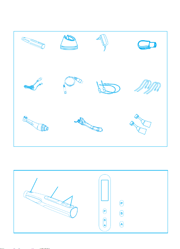
Fig. A Components and Accessories
Motor Handpiece
Battery Charger
AC Adapter
(CX265-28 (type C)
50.0007.011 (type I)
50.0007.010 (type G))
Tester
(CX265-67)
Test Wire A
(CX265-63)
Test Wire B
(CX265-64)
File Clip
(CX265-52)
Lip Hook
(CX265-17)
16:1 Contra-angle
(C4-2M)
Lighting Device
(CX265-23F)
Protective Sleeve
(CX265-65)
Fig. B Handpiece and Switch
Main switch
LCD Display
Switch
Program switch
Select/Set switch
Adjust switch

Fig. C Contra Angle & File connection
Fig. D Accessory Connection
Install
Remove

Fig. E Apex Locator Mode
Test Wire Jack
Fig. F Multi-function Mode
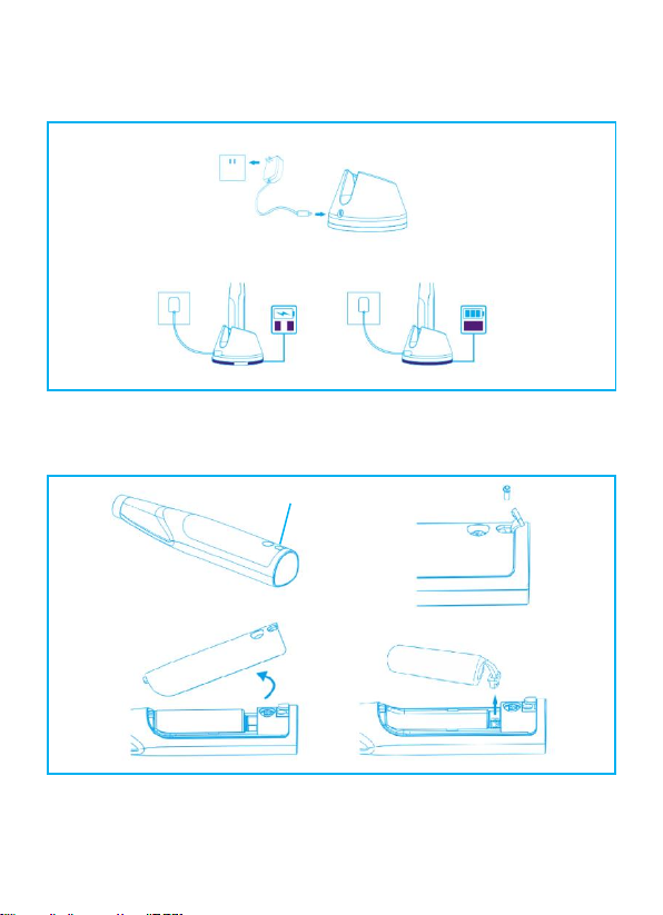
Fig. G Charging
Fig. H Replace the battery
Rubber Cover

Table of Contents
1. Attention ....................................................................1
1.1 Attention Customers ..........................................................................1
1.2 Prevent Accidents ..............................................................................1
1.3 Disclaimer ..........................................................................................3
1.4 In Case of Accident ............................................................................3
1.5 User Qualifications ............................................................................3
1.6 Intended Used ...................................................................................4
2. Usage ..........................................................................5
2.1 Operation and Storage Environments ...............................................5
2.2 Operation Modes ..............................................................................5
2.3 Power On/Off ....................................................................................5
2.4 Endo Motor Mode ............................................................................6
2.5 Apex Locator Mode .........................................................................14
2.6 Multi-function Mode .......................................................................19
3. EMR ..........................................................................21
4. Operation Check ......................................................23
4.1 Check with Tester ............................................................................23
4.2 Check Canal Measurement Function ..............................................23
5. Battery and Charging ..............................................25
5.1 Battery Power ................................................................................25
5.2 Battery Charging ............................................................................25
5.3 Replacement Battery .....................................................................27

6. Calibration and Settings ...........................................28
6.1 Enter Setting Mode ..........................................................................28
6.2 Calibration ........................................................................................28
6.3 Set Dominant Hand ..........................................................................29
6.4 Reset Memories to Original Default Settings ...................................30
7. Cleaning, Disinfection and Sterilization ...................31
8. Troubleshooting ......................................................36
9. Technical Specifications ..........................................37
10. Symbols..................................................................38
11. Guarantee .............................................................39
12. Disposal of Medical Devices ..................................39
13. EMC .......................................................................40
1
1. Attention
1.1 Attention Customers
Do not fail to receive clear instructions concerning the various ways to use
this device as described in this accompanying Operation Instructions.
1.2 Prevent Accidents
Most operation and maintenance problems result from insufficient attention
being paid to basic safety precautions and not being able to foresee the
possibilities of accidents.
Problems and accidents are best avoided by foreseeing the possibility of
danger and operating the device in accordance with the manufacturer’s
recommendations.
First, thoroughly read all precautions and instructions pertaining to safety and
accident prevention; then, operate the device with the utmost caution to
prevent either damaging the device itself or causing bodily injury.
WARNING:
This alerts the user of possibility of extremely serious injury or complete
destruction of the device as well as other property damage including the
possibility of fire.
CAUTION:
This alerts the user of possibility of minor or moderate injury or damage to
the device
NOTE:
Informs the user of important points concerning operation or the risk of
device damage.

2
Do not use this device for anything other than its specified dental treatment
purpose.
WARNING
No modification of this device is allowed.
PROHIBITION
Do not use this device on patients who have implanted pacemakers or
defibrillators.
IMPORTANT PRECAUTIONS
These caution remarks are especially critical for safe operation and use.
Do not use the wireless transmission devices listed below in the examination
area:
a) Cell phone terminals.
b) Wireless transmitting devices such as ham radios, walkie-talkies, and
transceivers.
c)Personal Handy-phone System.
d) Routers for intra-building paging systems, wireless LAN, cordless analogue
telephones, and other electric wireless devices.
• This device might be adversely affect by the electromagnetic radiation
produced by electric scalpels, illumination devices etc. that are being used
nearby.
• Do not perform maintenance while using the device for treatment.
2

3
1.3 Disclaimer
Manufacturer will not be responsible for accidents, device damage, or bodily
injury resulting from:
a) Repairs made by personnel not authorized by manufacturer.
b) Any changes, modifications, or alterations of its products.
c) Maintenance or repairs using parts or components other than those
specified by manufacturer and other than in their original condition.
d) Operating the device in ways other than the operating procedures
described in this manual or resulting from the safety precautions and
warnings in this manual not being observed.
e) Workplace conditions and environment or installation conditions which do
not conform to those stated in this manual such as improper electrical
power supply.
f) Fires, earthquakes, floods, lightning, natural disasters, or acts of God.
1.4 In Case of Accident
If an accident occurs, the device must not be used until repairs have been
completed by a qualified and trained technician authorized by the
manufacturer.
1.5 User Qualifications
Intended Operator Profile
a) Qualification: Legally qualified person such as dentists for endodontic
device operation (it may differ among countries).
b) Education and Knowledge: It is assumed the user is thoroughly familiar
with root canal measuring and treatment including the prevention of cross
contamination.

4
c) Language Understanding: English (Intended for professional use as
described above)
d) Experience: Experienced person with operating endodontic instrument.
1.6 Intended use
The Rooter® Universal is an electro-medical device intended to drive
mechanical instruments intended for dental root canal treatment (files).
In addition, it is intended to help to determine the working length (apex
locator functionality).

5
2. Usage
CAUTION:
•Do not expose the device to direct sunlight for an extended period of
time.
•If the device has not been used for some time, make sure it works
properly before using it again.
•Refer to the contra-angle operation manual for all operations regarding
the contra-angle.
2.1 Operation and Storage Environments
Operating Temperature: +5°C to +40°C
Humidity: 20% to 80% (without condensation)
Atmospheric Pressure: 80 kPa to 106 kPa
Transport and Storage Temperature: -10 °C to +55°C
Humidity: ≤93% (without condensation)
Atmospheric pressure: 50 kPa to 106 kPa
2.2 Operation Modes
The device has 3 modes:
Endo motor: Prepare the root canal, without apex locator function.
Apex Locator:Measure the length of the root canal, without motor function.
Multi-function: Measuring the length while root canal preparation.
2.3 Power On/Off
Hold down to turn power on/off.

6
CAUTION:
•Have components been sterilized? (Refer to chapter7)
•Is the battery sufficiently charged? (Refer to chapter 5.1)
2.4Endo Motor Mode
If not any test wire connected to the device, it’s in Endo Motor Mode.
Please refer to Fig. C, D
2.4.1 Connect the Components
a) Connect contra angle
Line up the projection inside the contra angle with the notch inside the
motor and slide it in until it clicks securely into place.
b) Connect file
Hold down the push button on the contra angle and insert the file. Turn the
file back and force until it is lined up with interior latch groove and slips into
place. Release the button to lock the file into the contra angle.
c) Connect lighting device
Insert the lighting device into the motor handpiece and clip the electrode
on the file.
WARNING:
•Make sure the connection ends of the motor handpiece and the contra
angle is not damaged. If these are damaged, the load on the contra angle
could cause the motor to reverse rotation, and this might result in an
injury to the oral cavity.
•Files are expendable, and they eventually wear out. Replace them before
they break.

7
•Never use stretched, deformed or damaged files.
•Make sure the file is all the way in. Give the file a light tug to confirm it is
securely held in place. If the file is not securely placed, it could come out
and injure the patient.
CAUTION:
•Be careful when inserting and removing files to avoid injury to fingers.
•Inserting and removing files without holding the push button may
damage the chuck.
•When installing/removing the lighting device, do not shake them at will
to avoid damaging the plug.
•Take care not to touch when installing or removing the file. This
will cause the file to rotate.
NOTE:
Hold down the push button on the contra angle and pull the file straight
out.
8
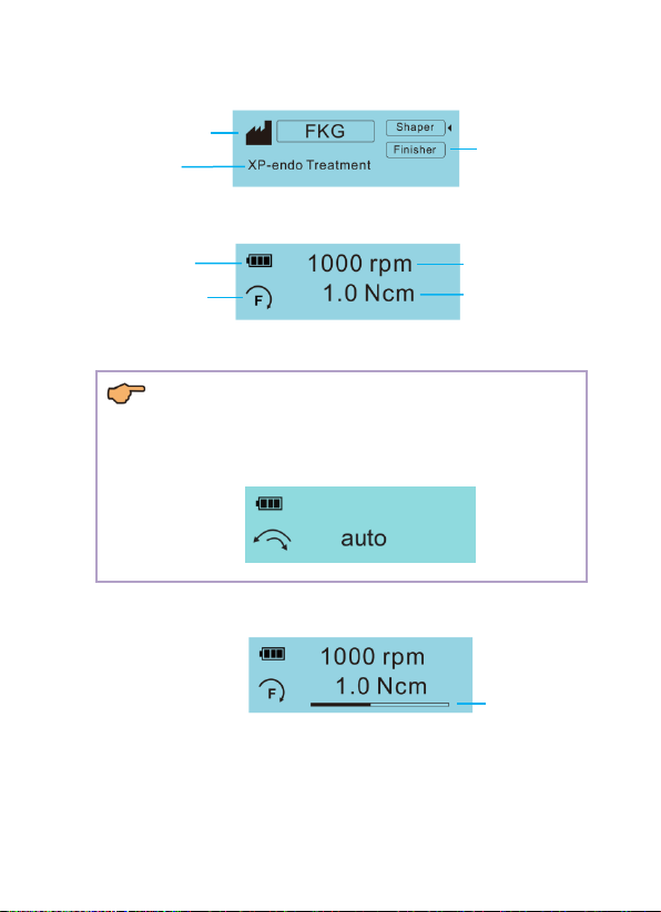
2.4.2 LCD Display
File Manufacturer
File
File System
Standby 1
Battery Power
Speed
Rotary Direction
Torque Limit
Standby 2
NOTE:
Some preset files have automatic parameters.
If such a file has been selected, the speed and torque value will display
“auto”.
Current Torque
Working

9
2.4.3 File systems libraries
The device contains libraries of file systems with preset parameters.
a) Hold down to enter selection interface and press again to select
the file systems library.
NOTE:
The change will be saved automatically. Press or to exit the
selection interface.
b) Press to choose the file system.
c) Press to choose the file.
WARNING:
•Follow the file manufacturer's instructions for use of endodontic files. Do not
use files designed for reciprocating motion in Continuous Rotary File Mode.
•The file system shown on the display must always match the file in use.
10
2.4.4 Start Working
a) Start Motor
Press to start the motor handpiece and press again to stop it.
The lighting device will continue to illuminate while the motor handpiece is
running.
WARNING:
If the contra angle’s file release button is pressed against the teeth
opposite the one being treated, the file could come out and injure the
patient. Before use, run the device outside the oral cavity to make sure it is
operating normally.
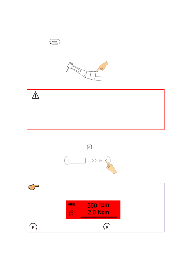
b) Change Motor direction of rotation
Only in User file systems, press to change the motor direction of rotation.
NOTE:
The screen is red when the motor rotates in the reverse direction.
Means forward rotation Means reverse rotation
11
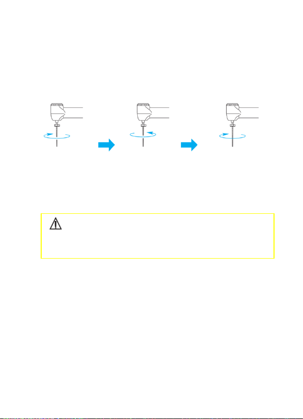
2.4.5 Auto Reverse
If, during operation the load reaches the preset torque limit value, the motor
handpiece will automatically rotate in the reverse direction. When the load is
reduced, the motor handpiece returns to normal forward rotation
automatically.
Load within the
torque limit value.
Load beyond the
torque limit value.
When the load is reduced,
the motor is automatically
restored.
CAUTION:
Do not apply excessive force. Even when using the torque reverse function,
files may break depending on the torque setting.

12
2.4.6 Change Speed and Torque
CAUTION:
•While the motor handpiece is in motion, speed and torque cannot be
changed;
•In User Recipro file system, torque cannot be changed.
•In all FKG file systems, rotation direction, speed, torque and rotation
angle cannot be changed. (fixed settings)
a) Hold down until the Speed flash and press again to select speed
or torque to adjust.
b) Press to adjust desired value.
c) The change will be saved automatically. Press to exit the setting, or
exit the setting automatically after a few seconds.
NOTE:
When the user changes the default parameter, its value will prompt [ ].
Other manuals for Rooter Universal
1
Table of contents
Other FKG Dental Equipment manuals


