FKG Rooter X3000 User manual

User Manual
12345678910 11 12 13 14 15 16 17 18
19 20 21 22 23 24 25 26

Table of Contents
1. Product introducon.................................................................................................... 1
1.1 Descripon of the device............................................................................................................................. 1
1.2 Components and accessories ...................................................................................................................... 2
1.3 Technical specicaons............................................................................................................................... 3
1.4 Warnings ..................................................................................................................................................... 3
1.5 Important precauons ................................................................................................................................ 4
1.6 Device safety classicaon.......................................................................................................................... 4
1.7 Environmental parameters.......................................................................................................................... 4
1.8 User qualicaon ........................................................................................................................................ 4
1.9 Intended use................................................................................................................................................ 4
2. Device setup instrucons ............................................................................................. 4
2.1 Contra-angle setup...................................................................................................................................... 4
2.2 File setup ..................................................................................................................................................... 5
2.3 Apex locator setup ...................................................................................................................................... 6
3. Device Operaon modes and display interface .......................................................... 8
3.1 Motor modes............................................................................................................................................. 8
3.2 Apex locator Operaon mode................................................................................................................... 9
3.3 Combined Motor and Apex locator Operaon mode ............................................................................... 9
3.4 Display interface........................................................................................................................................ 10
4. Device operang instrucons..................................................................................... 11
4.1 Seng interface and bun descripon .................................................................................................. 11
4.2 Power ON and power OFF the device ....................................................................................................... 11
4.3 Select User Programs ................................................................................................................................ 11
4.4 Set User Program parameters ................................................................................................................... 12
4.5 Select FKG FileSystems ............................................................................................................................. 14
4.6 Set device parameters............................................................................................................................... 16
4.7 Torque overload protecon ...................................................................................................................... 16
4.8 Apex locator limitaons ............................................................................................................................ 16
5. Troubleshoong......................................................................................................... 18
6. Cleaning, Disinfecon and Sterilizaon ...................................................................... 18
6.1 Foreword ................................................................................................................................................... 18
6.2 General recommendaons........................................................................................................................ 18
6.3 Step-by-Step Procedure ............................................................................................................................ 19
12345678910 11 12 13 14 15 16 17 18
19 20 21 22 23 24 25 26

7. Maintenance.............................................................................................................. 20
7.1 Calibraon ................................................................................................................................................. 20
7.2 Lubricaon of the contra-angle............................................................................................................... 20
7.3 Charging of the bry ............................................................................................................................. 20
7.4 Replacement of the baery ...................................................................................................................... 20
8. Storage ...................................................................................................................... 21
9. Transportaon ........................................................................................................... 21
10.Environmental protecon .......................................................................................... 21
11.Aer sales service ...................................................................................................... 21
12.Symbol instrucon ..................................................................................................... 21
13.Statement .................................................................................................................. 22
14.EMC-Declaraon of conformity.................................................................................. 23
14.1 Technical Descripon Concerning Electromagnec Emission................................................................... 23
14.2 Technical Descripon Concerning Electromagnec Immunity.................................................................. 23
12345678910 11 12 13 14 15 16 17 18
19 20 21 22 23 24 25 26

1. Product introducn
1.1 Descripon of thedevice
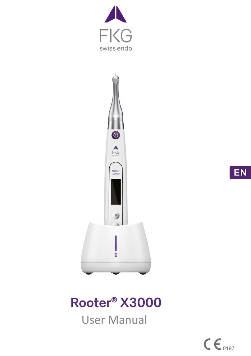
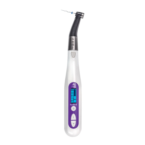
The Rooter®X3000 device is a cordless endo motor with an integrated root canal apex locator. It
can be used as an endo motor for preparaon of tooth root canals, or as an apex locator device
to help to determine the root canal working length. It can also be used to prepare the canals
while monitoring the relave poson of the endodonc instrument inside the canal
(combined Motor and Apex locator mode).
1 2345678910 11 12 13 14 15 16 17 18
19 20 21 22 23 24 25 26
Contra angle
OLED screen
Charging base
Charging LED indicator

1.2 Components and accessories
# Designaon Reference FKG
1 Motor handpiece 08.971.00.001.FK
2 Charging base 08.971.00.002.FK
3 Contra-angle [4.7/1]
08.971.00.003.FK
4 Spray noozle 08.971.00.004.FK
5 Measuring wire
08.971.00.005.FK
6 File clip 08.971.00.006.FK
7 Lip hook 08.971.00.007.FK
8 Touch probe 08.971.00.008.FK
9 Protecve silicone cover
08.971.00.009.FK
10 "O"-ring 08.971.00.010.FK
11 Universal AC-Adapter 08.971.00.011.FK
08.971.00.013.FK
08.971.00.014.FK
12
13 Measuring Wire - USB - C
- User manual -
- Package content list -
12345678910 11 12 13 14 15 16 17 18
19 20 21 22 23 24 25 26
1.Motor handpiece
2.Motor handpiece
3.Contra-angle
4.Spray noozle 6.File clip
10.O-ring
11.AC-Adapter
7.Lip hook
8.Touch probe
5.Measuring wire

1.3 Technical specicaons
a) Motor handpiece lithium baery speccaon
3.7V / 2000mAh
b) Power adapter specicaon
Input: ~100V-240V50Hz/60Hz 400mA
Output: DC5V/1A
c) Motor handpiece mechanical specicon
Torque range: 0.4Ncm-4.0Ncm
Speed range: 100rpm-3’300rpm
d) Wireless charging specicaon
Frequency range: 112-205KHz
Maximum RF output power of the product: 9.46dBuA/m@3m
1.4 Warnings
Please carefully read this Instrucon Manual before rst operon.
a) Do not use this device for anything else than its intended use (refer to Chapter 1.9).
a) Use original components and accessories only.
b) Always set torque and speed following the recommendaons of the e manufacturer.
c) Make sure the contra-angle is well connected before to start the motor handpiece (refer
to Chapter 2.1).
d) Make sure the instrument is well connected and locked before to start the motor
handpiece (refer to Chapter 2.2).
e) Do not connect or disconnect the contra-angle while the motor is running.
f) Do not disconnect the instrument while the motor is running.
g) Be sure to be able to power OFF the device at any me.
h) Operate and store the device in reliable environment (refer to Chapter 1.7 and Chapter
8).
i) Do not use the device in the vicinity of orescent lamps, radio transm devices,
remote control devices, handheld, and mobile high-frequency communicon devices.
j) The motor handpiece, power adapter and charging base are not autoclavable (refer to
Chapter 6).
k) Replace the lithium baery according to the instrucons (refer to Chapter 7.4).
l) Do not make any changes or modicons to the device. Any change, mocaon or any
other alteraon of the device may violate safety regulaons, causing harm to the paent.
m) In case of motor handpiece frequent overheat, contact a local distributor.
n) Do not directly or indirectly place the device near heat sources.
o) Do not cover the device.
p) Remove the baery of the device in case of long period storage.
12345678910 11 12 13 14 15 16 17 18
19 20 21 22 23 24 25 26

1.5 Important precauons
These precaons are critical to insure safe operon and use.
a) Do not use this device on paents who have implanted pacemakers, debrillators, or any
other implantable devices.
b) Do not use this device on paents sering from Hemophilia.
c) Use with con on paents with heart disease, pregnant women, and young children.
1.6 Device safety classicaon
a) Type of Operon mode: Couous oper electromedical device
b) Type of protecon against electric shock: Class II equipment with internal power supply
c) Degree of protecon against electric shock: B type applied part
d) Degree of protecon against harmful ingress of water: Ordinary equipment (IPX0)
e) Degree of safety applicaon in the presence of a mmable anesthec mixture with air,
oxygen, or nitrous oxide: Equipment cannot be used in the presence of a mmable
anesthec mixture with air, oxygen, or nitrous oxide.
f) Applied part: contra-angle , lip hook, e clip, touch probe.
The contact duron of applied part: 1 to 10 minutes.
Maximum temperature of applied part: 46.6°C.
1.7 Environmental parameters
a) Opera ambient temperature: +5°C ~ +40°C
b) Opera reve humidity: 30% ~ 75%
c) Opera atmospheric pressure: 70kPa ~ 106kPa
1.8 Userqualicaon
a) The device must be operated in hospital or clinic by legally quaed dests.
b) It is assumed that the operator is familiar with root canal apex locator.
1.9 Intended use
a) The Rooter®X3000 is an endo motor, an electro-medical device intended to drive
mechanical instruments intended for dental root canal treatment (endodoc es).
b) In on, it is intended to help to determine the working length (apex locator
funconality).
2. Device setup instrucns
2.1 Contra-angle setup
2.1.1 Before the rst use and er each treatment
a) Clean and disinfect the contra-angle (refer to Chapter 6).
b) Lubricate the contra-angle (refer to Chapter 7.2).
c) Sterilize the contra-angle (refer to Chapter 6).
2.1.2 Warnings
a) Use original contra-angle only.
b) Make sure the contra-angle is well connected before to start the motor handpiece.
c) Do not connect or disconnect the contra-angle while the motor is running.
2.1.3 Connec the contra-angle
1. Align the three pins of the contra-angle with the posoning slots of the motor handpiece.
12345678910 11 12 13 14 15 16 17 18
19 20 21 22 23 24 25 26

2. Push the contra-angle horizontally. A “click” sound indicates that the instaon is in
place.
3. The contra-angle must rotate 360° freely.
2.1.4 Disconnecng the contra-angle
Pull out the contra-angle horizontally.
2.2 File setup
2.2.1 Warnings
a) Make sure the instruments are compliant to ISO1797 standard (Shanks for rotary and
osc instruments).
b) Connec and disconnec es without holding down the Push buon may damage
the chuck of the contra-angle.
c) Be careful when manipula es to avoid injury to ers.
d) Make sure the e is well connected and locked before to start the motor handpiece.
e) Do not disconnect the le while the motor is running.
2.2.2 Connec a
Plug the e into the hole of contra-angle head.
1. Hold down the Push buon on the contra-angle and push the e.
2. While pushing, rotate the e clockwise and counterclockwise its shank is aligned
with the contra-angle latch groove.
3. When the shank is aligned and slips into place, release the Push on to lock the e
into the contra-angle.
12345678910 11 12 13 14 15 16 17 18
19 20 21 22 23 24 25 26

2.2.3 Disconnecng a
Hold down the Push buon and pull out the e.
2.3 Apex locator setup
2.3.1 Warnings
a) In Apex locator mode, the e clip must properly hold the le.
b) In case of bad or wrong connecon signal, replace the measuring wire.
c) In apex locator mode it is suggested to install the motor handpiece in the charging base
to get beer visual angle.
12345678910 11 12 13 14 15 16 17 18
19 20 21 22 23 24 25 26

d) The Apex locator detects the canal apical foramen, not the tooth anatomical apex. This
could explain some erences between the apex locator signal and an X-ray image.
e) Not all condons are ideal for working length determinaon. To be informed about the
Apex locator limitaons, refer to Chapter 4.8.
2.3.2 Connec apex locator wires
1. Connect the measuring wire to the motor handpiece (USB socket at the back).
2. Connect the lip hook to the white socket of the measuring wire.
3. Connect the e clip plug to the black socket of the measuring wire (this is not required in
combined Motor and Apex locator mode).
12345678910 11 12 13 14 15 16 17 18
19 20 21 22 23 24 25 26

2.3.3 Connecon tes
It is strongly recommended to check the connecon quality before every use.
1. In Apex locator mode, clip the holder on lip hook and check that all the indicator bars light
up, as shown below:
2. In combined Motor and Apex locator mode, touch the lip hook with the e and check
that all the indicator bars light up, as shown below:
3. Device Operaon modes and display interface
3.1 Motor modes
3.1.1 CW Operaon Mode (Clockwise conous rotaon mode)
In this mode, the motor handpiece rotates in clockwise direcon only (forward direcon).
3.1.2 CCW Operaon Mode (Counterclockwise conuous rotaon mode)
In this mode, the motor handpiece rotates in counterclockwise direcon only (reverse direcon).
In this mode, a double beepsounds coously.
3.1.3 REC Operaon Mode (Reciproca moon mode)
In this mode, the motor handpiece generates reciproca moon only (F: Forward angle, R:
Reverse angle).
12345678910 11 12 13 14 15 16 17 18
19 20 21 22 23 24 25 26

3.1.4 ATR Operaon Mode (Ave Torque Reverse mode)
In this mode, the motor handpiece rotates in clockwise direcon and generates reciprocag
moon when the torque load on the e is higher than the set torque limit.
3.2 Apex locator Operaon mode
3.2.1 EAL Operaon Mode (Electronic Apex Locator)
This mode is intended for working length determon only.
In this mode, the motor handpiece does not run.
3.3 Combined Motor and Apex locator Operaon mode
When a e is inside the canal and the lip hook is in contact with ent’s lip, the device enters
automacally in the combined Motor and Apex locator mode.
12345678910 11 12 13 14 15 16 17 18
19 20 21 22 23 24 25 26

3.4 Display interface
Stand-by interfaces
While the motor is not running, the display shows the actual sengs of the
motor.
a. User Program (M0-M9)
or
Manufacturer preset program (refer to Chapter 4.5)
b. ry level
c. Set speed (rpm)
d. Set torque limit (Ncm)
e. Motor Operaon mode
f. Set forward angle (°deg)
g. Set reverse angle (°deg)
Motor Operaon interface
While the motor is running, the display shows the torque load on the e.
a. Set speed (rpm)
b. Set torque limit (Ncm)
c. Real me torque (Ncm)
d. Torque display scale (Ncm)
Combined Motor and Apex locator Operaon interface
a. Fileprogression indicaon bar
b. File progression indicaon number
The numbers 1.0, 2.0, 3.0 (a) and numbers “00”-“16” (b) do not represent
an absolute length. It simply indicates the relae le posion towards the
apical foramen. These numbers are used to help the determinaon of the
working length.
c. Apical foramen (AP)
The digital number “00” (b) indicate that the e has reached the apical
foramen. The digital numbers “-1” and “-2” (b) indicate that the e has
passed the apical foramen.
Apex locator Operaon interface (EAL mode)
a. User Program (M0-M9)
b. ry level
c. File posion indicaon bar
d. Apical reference point
e. Motor Operaon mode
12345678910 11 12 13 14 15 16 17 18
19 20 21 22 23 24 25 26
XP-endo T.
Shaper
f
g

4. Device operang instrucons
4.1 Seng interface and bon descripon
4.2 Power ON and power OFF thedevice
1. To power ON the device, press the Main on. The device enters in stand-by state.
The display shows the stand-by interface of the last program used. For example:
or or …
2. To start the motor from the stand-by state, press the Main on.
The display shows the working interface according to the program used. For example:
3. To stop the motor, press the Main on again. The device goes back in stand-by state.
4. To power OFF the device, hold down the Seng on “P”, and press the Main on.
In stand-by state, the device will automacally shut down er 5 minutes.
4.3 Select User Programs
The device contains 10 memorized User Programs (M0-M9) and 7 preset FKG File Systems
available directly from the stand-by state.
1. To select a program from the stand-by state, press the Adjuson “+”/”-“.
… …
…
2. To select a specc FKG File System, refer to Chapter4.5.
12345678910 11 12 13 14 15 16 17 18
19 20 21 22 23 24 25 26
XP-endo T.
Shaper 1000rpm
1.0Ncm
XP-endo T.
Shaper 1000rpm
1.0Ncm
XP-endo T.
Finisher 1000rpm
1.0Ncm
RACE EVO
All files 1000rpm
1.5Ncm
XP-endo R.
DR1 1000rpm
1.5Ncm
XP-endo R.
Finisher R 1000rpm
1.0Ncm
XP-endo R.
Shaper 2500rpm
1.0Ncm
R-Motion
All files F: auto
REC R: auto
R-Motion
All files F: auto
REC R: auto
250rpmM9
CW 2.0Ncm

4.4 Set User Program parameters
4.4.1 Warnings
a) Make sure the Operaon Mode is adequate before to start the motor.
b) All the parameters must be set according to the e manufacturer recommendaons.
c) Make sure all the parameters are vered before to start the motor handpiece.
d) M0-M9 User Programs parameters moed by the user are memorized.
e) FKG File Systems parameters cannot be modied by the user (refer to Chapter 4.5).
4.4.2 Parameter se
To modify User Program parameters from the stand-by state:
1. To select the desired parameter, press the Seng on “P”.
2. To modify the parameter se press the Adjus on “+”/“-”.
3. Press the Main on or wait 5 seconds to conrm.
4.4.3 User Program parameters list
Set Operaon Mode
Operaon modes list: CW, CCW, REC, ATR, EAL
(refer to Chapter 3 for modes descripon)
Set Working Speed
In connuous rotaon modes (CW and CCW), the working speed can be adjusted from
100rpm to 3’300rpm (50rpm increments).
In REC mode, the working speed can be adjusted for 100rpm to 500rpm (50rpm
increments).
In ATR mode, the working speed can be adjusted for 100rpm to 500rpm (50rpm
increments).
In REC and ATR modes, the working speed represents the mean speed of one single
angle movement (speed set for both Forward and Reverse angles).
Set Torque Limit
In CW connuous rotaon mode, the torque limit can be adjusted from 0.4Ncm to
4.0Ncm depending on the set speed:
•100-200rpm Max torque limit : 4.0Ncm
•250-400rpm Max torque limit : 3.5Ncm
•450-650rpm Max torque limit : 3.0Ncm
•700-950rpm Max torque limit : 2.5Ncm
•1’000-1’450rpm Max torque limit : 2.0Ncm
•1’500-1’950rpm Max torque limit : 1.5Ncm
•2’000-3’300rpm Max torque limit : 1.0Ncm
In REC mode, the torque limit can be adjusted from 2.0Ncm to 4.0Ncm depending on
the set speed:
•100-250rpm Max torque limit : 4.0Ncm
•300-400rpm Max torque limit : 3.5Ncm
•450-500rpm Max torque limit : 3.0Ncm
In ATR mode, the Trigger Torque can be adjusted from 0.4Ncm to 3.0Ncm.
In CCW connuous rotaon mode, the torque limit cannot be set.
12345678910 11 12 13 14 15 16 17 18
19 20 21 22 23 24 25 26
Operation Mode
CW
Speed
250rpm
Torque Limit
1.0Ncm

Set Apical Acon
The Apical acon applies when the e reaches the set apical reference point (refer
to Flash Bar Posion)
OFF: Disable Apical Acon
STOP: The motor stops automacally when the e reaches the reference point. The
motor restarts automacally when the e is pulled away from the reference point.
REVERSE: The motor automacally reverses the rotaon direcon when the e
reaches the reference point. The motor goes back automacally to inial rotaon
direcon when the e is pulled away from the reference point.
Set Auto Start
OFF: Disable Auto Start (the Main buon is needed to start the motor handpiece).
ON: The motor starts automacally when the e is inserted into the canal (from when
the le progression indicator shows 2 bars).
Set Auto Stop
OFF: Disable Auto Stop (the Main buon is needed to stop the motor handpiece).
ON: The motor stops automacally when the e is taken out the canal.
Set Flash Bar Posion (Apical reference point)
The apical reference point (ash bar) can be set from 2 to AP (Apical foramen).
(0.5 indicates that the e p is located very near the physiological apical foramen)
Apical Acon and Apical Slow Down are triggered by the apical reference point.
Set Apical Slow Down
When the Apical Slow Down is acvated, the motor slows down to a set nal speed
as the e ps approaches the apical reference point. The motor speed decreases
starng from the posion “3.0” of the file progression indicaon bar .
OFF: Disable Apical Slow Down
In CW connuous rotaon mode, the nal speed can be adjusted from 100rpm to the
current set speed (50rpm increments).
The Apical Slow Down funcon is available for CW & CCW connuous rotaon mode
only.
The nal speed must be lower than the nominal speed.
Forward Angle
In REC mode, the Forward Angle can be adjusted from 20° to 400° (10° increments)
In ATR mode, the Forward Angle can be adjusted from 60° to 400° (10° increments).
Reverse Angle
In REC mode, the Reverse Angle can be adjusted from 20° to 400° (10° increments)
In ATR mode, the Reverse Angle can be adjusted from 20°to the Forward Angle (10°
increments).
12345678910 11 12 13 14 15 16 17 18
19 20 21 22 23 24 25 26
Apical Slow Down
200rpm

4.4.4 User Programs parameters availability table
Parameter
User Program
Operaon Mode
Set
Working
Speed
Set
Torque
Limit
Set
Apical
Acon
Set Auto
Start
Set Auto
Stop
Set Flash
Bar
Posion
Set
Apical
Slow
Down
Set
Forward
Angle
Set
Reverse
Angle
CW
YES
YES
YES
YES
YES
YES
YES
n/a
n/a
CCW
YES
NO
NO
NO
NO
YES
YES
n/a
n/a
REC
YES
YES
YES
YES
YES
YES
NO
YES
YES
ATR
YES
YES
YES
YES
YES
YES
NO
YES
YES
EAL
n/a
n/a
n/a
n/a
n/a
YES
n/a
n/a
n/a
4.5 Select FKG File Systems
To help the user set the e parameters according to FKG recommendaon, the most popular
FKG File Systems are already preset in the device.
1. To select a preset FKG File System from the stand-by state, long press the Se buon
“P”.
2. To select the desired FKG File System, press the Adjus on “+”/“-” and press the
Se on “P” to corm.
3. To select a le, press the Adjus bon “+”/“-” and press the Main on to corm.
4.5.1 FKG File Systems list
RACE®EVO
File systems selecon
File selecon
Stand-by interface
Operaon interface
XP-endo®Treatment
File systems selecon
File selecon
Stand-by interface
Operaon interface
XP-endo®Retreatment
File systems selecon
File selecon
Stand-by interface
Operaon interface
12345678910 11 12 13 14 15 16 17 18
19 20 21 22 23 24 25 26
XP-endo T.
Shaper 1000rpm
1.0Ncm
XP-endo T.
Shaper 1000rpm
1.0Ncm
XP-endo R.
DR1 1000rpm
1.5Ncm
XP-endo R.
Shaper 2500rpm
1.0Ncm
XP-endo R.
Finisher R 1000rpm
1.0Ncm
RACE EVO
All files 1000rpm
1.5Ncm
2500rpm 1000rpm 1000rpm
DR1
Shaper
Finisher R
CW
1000rpm
1.0Ncm
Finisher R
DR1
Shaper
Finisher R
CW
2500rpm
1.0Ncm
Shaper
DR1
Shaper
Finisher R
CW
1000rpm
1.5Ncm
DR1
Shaper
Shaper
CW
1000rpm
1.0Ncm
Finisher
Shaper
Finisher
CW
1000rpm
1.0Ncm
Shaper
CW
1000rpm
1.5Ncm
All files

R-Moon®
File systems selecon
File selecon
Stand-by interface
Operaon interface
4.5.2 FKG File Systems parameters availability table
Parameter
FKG File System
Set
Working
Speed
Set
Torque
Limit
Set
Apical
Acon
Set Auto
Start
Set Auto
Stop
Set Flash
Bar
Posion
Set
Apical
Slow
Down
Set
Forward
Angle
Set
Reverse
Angle
RACE EVO
All Files
YES YES YES YES YES n/a n/a
XP-endo Treatment
Shaper
YES YES YES YES YES n/a n/a
XP-endo Treatment
Finisher
YES YES YES YES YES n/a n/a
XP-endo Retreatment
DR1
YES YES YES YES YES n/a n/a
XP-endo Retreatment
Shaper
YES YES YES YES YES n/a n/a
XP-endo Retreatment
Finisher R
YES YES YES YES YES n/a n/a
R-Moon
All Files
YES YES YES YES NO
4.6 Set device parameters
To set the device parameters:
1. To access the device parameters from the power OFF state, hold down the Se on
“P” and press Main buon.
2. To select the desired parameter, press Se on “P”
3. To set the parameter, press the Adjus on “+”/“-” and the Main on to conrm.
4.6.1 Device parameters list
Auto Power OFF
In stand-by state, the device automacally turns OFF r the set mer.
The mer can be adjusted from 3 minutes to 30 minutes (1 minute increments)
Auto Standby Scr
The display switches automacally back to the stand-by interface r the set mer.
The mer can be adjusted from 3 seconds to 30 seconds (1 second increments)
Dominant Hand
The device can be adjusted for l-handed or right-handed user (180° rotaon of the
display).
12345678910 11 12 13 14 15 16 17 18
19 20 21 22 23 24 25 26
Software Version
V1.0.0
R-Motion
All files F: auto
REC R: auto
--rpm
REC
auto
auto
All files

Calibraon
Make sure the original contra-angle is installed before to launch the motor
calibraon.
OFF: No acon.
ON: Start motor calibraon
The motor must be calibrated before the rstuse and aer lubricaon.
Beeper volume
The device sound volume can be adjusted from Vol. 0 to Vol. 4.
Vol.0: Mute.
Restore Defaults
OFF: No acon.
ON: Device parameters returns to original seng.
4.7 Torque overload protecon
During operon, if the measured torque load exceeds the torque limit, the motor will
automacally reverse the direcon of roon. The motor returns to Operaon mode (CW)
when the torque load goes back below the torque limit.
4.7.1 Warnings
a) In reciprocaon moon mode (REC), when the load value is higher than the torque limit:
i. if the Forward angle is greater than the Reverse angle, the motor automacally
switches to counterclockwise rotaon (reverse direcon).
ii. if the Reverse angle is greater than the Forward angle, the motor automcally
switches to clockwise rotaon (forward direcon).
b) The auto-reverse protecon is not available for CCW and ATR modes.
c) The auto-reverse protecon might not work properly in case of low baery level.
d) Under connuous load, the motor may stop automacally due to overheat. In that case,
the device must be powered OFF enough me to naturally cool down.
4.8 Apex locator limitaons
Not all condons are ideal for root canal length evaluaon. Accurate signal cannot be obtained
if the root canal shows the condions listed below.
12345678910 11 12 13 14 15 16 17 18
19 20 21 22 23 24 25 26

Rootcanal with a large apical foramen
Root canal with exceponally large apical foramen due
to a lesion or incomplete development might disturb the
electrical signal.
Rootcanal with liquid overowing from the opening
Root canal with blood or any other liquid overowing
from the opening and in contact with the gingival ssue
might disturb the electrical signal.
Broken crown
If the crown is broken and a secon of the gingival ssue
intrudes into the cavity surrounding the canal opening,
the contact between the gingival ssue and the le might
disturb the electrical signal.
Fractured tooth
Fractured tooth might disturb the electrical signal.
Re-treated root canal led with gua-percha
Debris of gua-percha might disturb the electrical signal.
Crown or metal prosthesis touching gingival ssue
The contact between the prosthesis and the le might
disturb the electrical signal.
12345678910 11 12 13 14 15 16 17 18
19 20 21 22 23 24 25 26
Other manuals for Rooter X3000
1
Table of contents
Other FKG Dental Equipment manuals
