Supply air unit VEKC - Integrated Control Equipment Curo
5
FläktGroup DC_9965GB_20190124_R3 Specifications are subject to alteration without notice
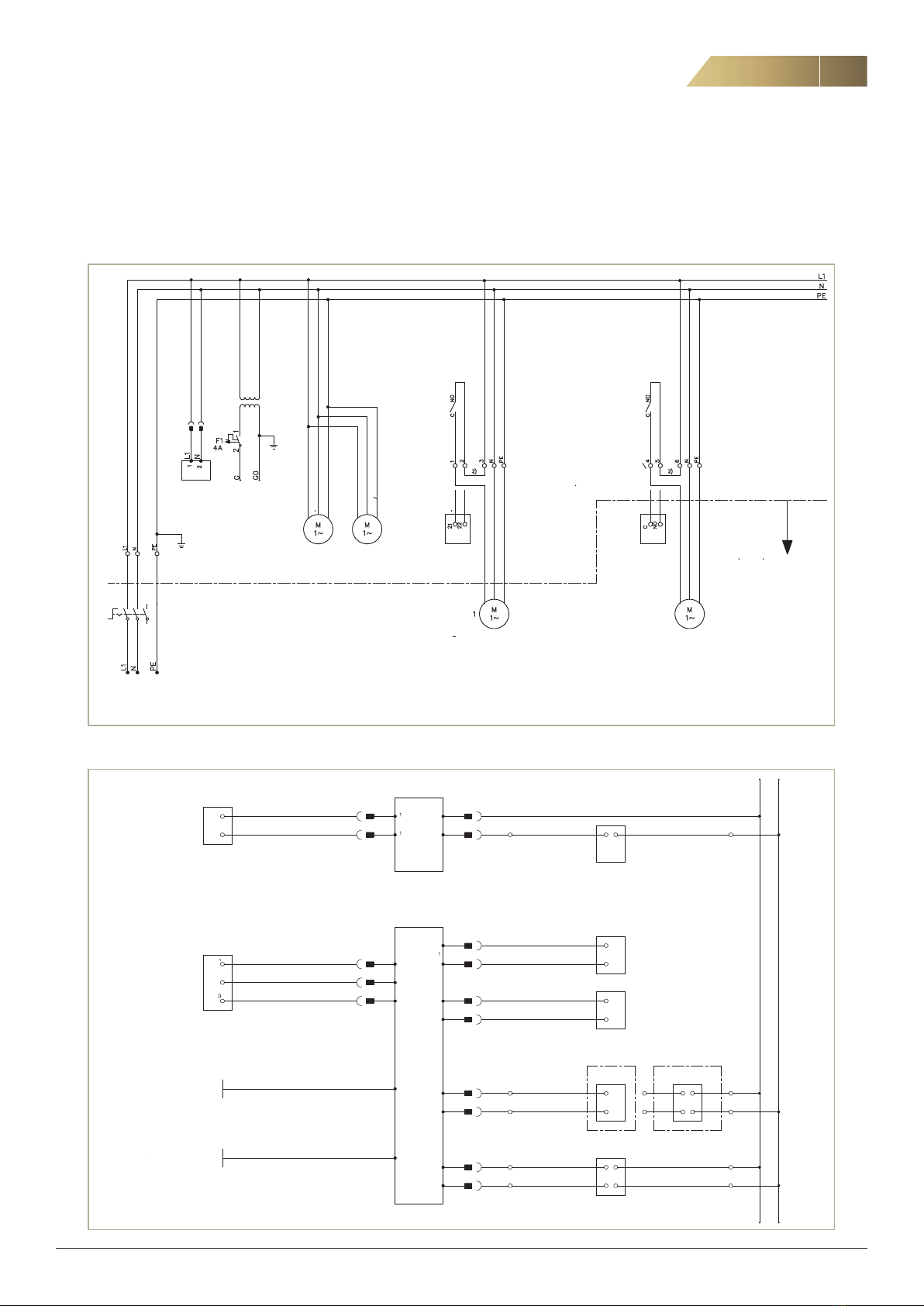
2.1 ELECTRICAL POST HEATER
Duct mounted. Separate supply 3 x 400V.
Connect alarm, start and control signal to the control box. The unit
is preconfigured for electrical post heater.
Component Designation Connection Remark
Electrical
heater
CP1/SK1
Heating
1 - 2
C - NO Start signal
ALM CP1 25 - 261) Alarm, overheating (NC)
SV1 CTRL 21 - 22
Y - M Control signal 0-10 V
Supply 3 x 400 V Not from the unit
1) Connects directly to the control board.
2.2 POST HEATER, HOT WATER
Circulation pump (CP1) and valve actuator (SV1) connects
according to table below.
Component Designation Connection Remark
Circulation
pump CP1
CP1/SK1
Heating 1 - N - PE Pump supply
(230 V max 2A2))
CP1/SK1
Heating
2 - 3
NO - L1
Loop only with cir-
culation pump
ALM CP1 25 - 261) Voltfree alarm input
(NO, configurable)
Valve
actuator SV1 SV1 CTRL 21 - 22 - 23 - 24
Y - M - G - GO
1)
Connects directly to the control board.
2)
The current consumption for CP1 and CP2 is limited to 2 A.
A separate safety switch for the pump is needed if it is a long
distance between the pump and the AHU.
2.3 COOLING COIL, WATER
Circulation pump (CP2) and valve actuator (SV2) connects
according to table below.
Component Designation Connection Remark
Circulation
pump CP2
CP2/DX
Cooling 4 - N - PE Pump supply
(230 V max 2A2))
CP2/DX
Cooling
5 - 6
NO - L1
Loop only with
circulation pump
ALM
CP2/DX 39 - 401) Voltfree alarm input
(NO, configurable)
Valve
actuator SV2 SV2 CTRL 25 - 26 - 27 - 28
Y - M - G - GO
1)
Connects directly to the control board.
2)
The current consumption for CP1 and CP2 is limited to 2 A.
A separate safety switch for the pump is needed if it is a long
distance between the pump and the AHU.
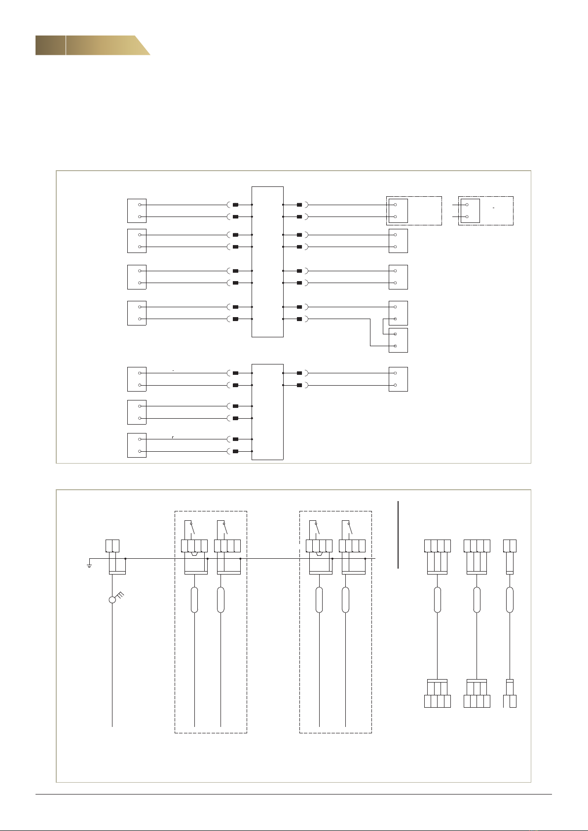
2. CONNECTION OF EXTERNAL COMPONENTS
2.4 COOLING COIL, DX
The unit can manage cooling DX, 1-step. Note that the coil is not
included in the delivery of the unit. For configuration see control
functions.
Component Designation Connection Remark
DX-cooling,
1-step
CP2/DX
Cooling
4 - 5
C - NO
Start: 10 %
Stop: 0 %
ALM CP2/DX 39 - 40 1) Voltfree alarm input (NO,
configurable)
1) Connects directly to the control board.
2.5 SPJÄLL
On/off actuator with spring return, 15 Nm, 24 VAC.
Component Designation Connection Remark
Damper ST1 29 - 30
G - GO
Exhaust air damper if used
is connected in parallel
(Maximum 2 dampers)
2.6 TEMPERATURE SENSORS
The unit is provided with:
Supply air sensor GT1, delivered separately. Duct mounting. Cable
not included.
Room temperature sensor GT2 (accessory) is supplied when the
unit is configured for room temperature control. The room sensor
is intended for wall mounting and needs to have good air circula-
tion and not direct sun light. Cable not included.
Outdoor air sensor GT3 (accessory) is supplied when the unit is
configured for outdoor air compensation. Duct mounting. Cable
not included.
Frost protection sensor GT5 is supplied when hot water coil is
used. Immersion sensor.
Component Designation Connection Remark
Supply air sensor GT1 46 - 471) Duct mounting
Room temperature
sensor GT2 50 - 511) Wall mounting
Outdoor air sensor GT3 48 - 491) Duct mounting
Frost protection
sensor GT5 52 - 531) Immersion sensor
1) Connects directly to the control board.
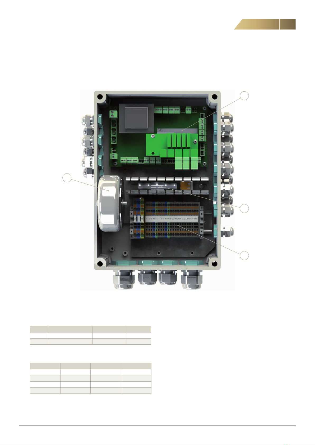
Use the control box on the outside of the unit to connect all exter-
nal accessories. For information about how to connect available
accessories see below.