flamco logoEco A2RXE Manual

GB
Technical information for installation and operation
LogoEco Heat Interface Unit (HIU) A2RXE
Instantaneous Hot Water & Space Heating

32
1. Operation 4
1.1 Space heating (SH) 4
1.2 Domestic hot water (DHW) 4
1.3 Priority switching 4
2. General Plumbing Requirements 5
2.1 British and Irish standards 5
сѵс $//$)")(*$ޔ/$*). ф
2.3 District heating 6
2.4 Space heating 6
2.5 Domestic water 7
2.6 Servicing 7
3. General Wiring Requirements 8
3.1 Danger of short circuit 8
4. Application 9
4.1 Status indicator LED 9
фѵ + $ޔ/$*) рп
5.1 Facts And Figures 11
6. Installation 12
7. Service 15
7.1 Filling the space heating system 15
7.2 Air venting the HIU 15
7.3 Room thermostat 17
7.4 Power supply 18
7.5 Commissioning 19
7.6 Removing and securing the case 20
7.7 Grundfos Pump 21
7.8 Performance viewview 21
7.9 Hot Water Circulation 22
цѵрп $Ȃ - )/+0(+(* . ст
7.11 Heat Meter 24
7.12 Troubleshoot (technician) 25
8. Appendix A 27
Appendix B 31
Appendix C 32
Contents Symbols and abbreviations
Symbols
Abbreviations
CAUTION, general safety remark
CAUTION, risk of shock
CAUTION, hot surfaces, risk of burns
CAUTION, hot water, risk of burns
Important note
Requirement of 230 Volt Alternating Current
Dispose component
Recycle component if possible
Wrench, manual tool
Drill, power tool
Manual operation, no tools needed
Philips Screwdriver
).0'/ ޕ/# .- 2-$1 -
DH District heating
SH Space Heating
DHW Domestic Hot Water
DCW Domestic Cold Water
VAC Volts Alternating Current
VDC Volts Direct Current
A Current in Ampere
N 230VAC Neutral
L 230VAC Live (phase)
PE Protective Earth
ºC Temperature in degrees
Celsius
kPa Pressure KiloPascal
kg Weight in Kilograms
mm Distance in millimetres
PN Pressure class in Bar
“ Thread size in inch (ISO
228/1)
HIU Heat Interface Unit
ABV Automatic Bypass Valve
230 V
insulated

54
1. Operation
1.1 Space heating (SH)
The heat exchanger physically separates the district heating network from the space heating circuit. The application
minimizes the risk of contamination of district heating water as well as the risk and consequences of leakage in the space
heating circuit. The electronic regulator in the unit, together with electronic control valves and temperature sensors
regulates the temperature of the space heating.
CAUTION!
Components, pipes and radiators in, and connected to, the unit may be hot. The heat interface unit is
designed for use with space heating systems up to 90ºC. The pipes and components in the unit as well as the
pipes and radiators in the space heating installation can reach these temperatures. Contact may lead to burns.
1.2 Domestic hot water (DHW)
The HIU is equipped with single wall plate heat exchangers. The heat exchanger transfers the heat from the heat
distribution system to the domestic hot water. The electronic controller in the unit, together with electronic control valves,
/ (+ -/0- . ).*-.)ޕ*2. ).*-- "0'/ ./# / (+ -/0- *!/# #*/2/ -/*$/.. /+*$)/җ !0'/фф٠Ҙѵ
The unit has two DHW keep hot modes – Eco or Comfort mode. The default setting is Eco mode and in this mode the heat
3#)" -$.& +/0+/*/ (+ -/0- !*-р#*0-ȅ -/# './#*/2/ --2*Ȃѵȅ -р#*0-*!$)/$1$/4/# / (+ -/0- $.
allowed to drop to minimize energy consumption. The comfort mode setting is optional and can be selected at the point
of commissioning. In this mode the heat exchanger is continuously kept warm for quicker hot water delivery. To prevent
' "$*) ''!-*("-*2$)"Ѷ/# # / 3#)" -$.# / /*фф٠ 1 -4су#*0-.!*-/' ./тп($)0/ .ѵ# )/# 0)$/$.ޔ//
with the optional DHW circulation pump, the unit must be set to comfort mode.
CAUTION! Hot water
The hot water temperature is regulated to 55ºC (default value). If there is a power outage during tapping
conditions the unit will stop regulating the domestic hot water temperature. This may lead to a domestic hot
water temperature that is higher or lower than its set point. Hot water can cause burns.
1.3 Priority switching
# $.ޔ// 2$/#+-$*-$/4.2$/#$)"ѵ# )#*/2/ -$.-2)*ȂѶ/# $1 -/.''/# ޕ*2/*# /0+/# *( ./$
water. If there is a power outage during tapping conditions or during a situation where there is no request for heat from the
(connected) thermostat, the space heating valve will stay in closed position. This may lead to a decrease in temperature of
the space heating installation/circuit.
# )$)./''$)"*(+' / '4) 2.4./ ($)) 20$'+-*+ -/4*-ޔ-.//$( $)./''/$*)$)) 3$./$)"+-*+ -/4Ѷ/# )
the heating system must conform to current building regulations Part L1a.
The appliance must be installed in accordance with, and comply to, the current: IEE Regulations, Building Regulations,
Building Standards (Scotland) (Consolidation), Building Regulations (Northern Ireland), local water by-laws, Health & Safety
Document 635 (The Electricity at Work Regulations 1989) and any other local requirements.
2.1 British and Irish standards
# - )*.+ $ޔ$)./-0/$*)$."$1 )Ѷ- ! - ) .#*0' ( /*/# - ' 1)/-$/$.#)ҝ*--$.#/)-* .*!
Practice.
BS7074:1 Code of practice for domestic and hot water supply
EN12828 Space heating for domestic premises
BS7593 Treatment of water in domestic hot water space heating systems
ECTI National rules for electrical installations
Keep following conditions in mind during installation:
• The HIU can only be used with closed heating systems up to a temperature of 90ºC.
• The HIU must be stored and installed in a frost free area.
• The HIU must not be exposed to direct sunlight.
• Ambient temperature must be between +5ºC and +40ºC.
• Humidity must be between 20% and 80%.
• Temperatures of components in the HIU and connected to the HIU can reach high temperatures. Contact may lead
to burns.
сѵс$//$)")(*$ޔ/$*).
Fitting the appliance and any controls to the appliance may only be carried out by a competent engineer. Any misuse or
0)0/#*-$. (*$ޔ/$*)./*/# ++'$) *-..*$/ *(+*) )/.).4./ (.*0'$)1'$/ /# "0-)/ )
may lead to serious injury or even death. The manufacturer accepts no liability arising from any such actions, excluding
statutory rights.
2. General Plumbing Requirements

76
2.3 District heating
CAUTION!
Components, pipes and radiators in, and connected to, the unit may be hot. The heat interface unit is designed
for use with centralized heating systems up to 90ºC. The pipes and components in the HIU as well as the pipes
and radiators in the space heating installation can reach these temperatures. Contact may lead to burns.
Keep following conditions in mind during installation:
• Maximum pressure supplied by the district heating network is 16 bar.
• 3$(0($Ȃ - )/$'+- ..0- .0++'$ 4/# $./-$/# /$)") /2*-&$.сфп&ѵ
җуфп&2# )$Ȃ - )/$'- ..0- *)/-*''1 җҘ$.ޔ// Ҙ
• Maximum supplied temperature by the district heating network is 90ºC.
• Minimal supply temperature is set-point DHW + 5ºC.
2.4 Space heating (SH)
!*- /# $.*(($..$*) Ѷ/# $-0$/(0./ ޔ// 2$/#)0/*(/$4Ҋ+..1'1 /*($)/$)($)$('ޕ*2
-/ *1 -/# ѵ# 1'1 (0./ $)./'' /2 )/# .0++'4)- /0-)Ѷ)*/$)"/# $- /$*)*!ޕ*2ѵ
*-*+/$(' ) -"4 Ȃ$$ )4)*(!*-/Ѷ$/$.*!/# 0/(*./$(+*-/)//*#4-0'$''4') /# $-0$/*-- /'4ѵ
For the same purpose it is advised to design the SH circuit in such a way, that the SH return temperatures are as low as
possible.
Keep following condition in mind during installation:
• -/$ޔ$''4.*ȅ ) 2/ -(0./)*/ 0. /*ޔ''/# .+ # /$)".4./ (
2. General Plumbing Requirements
ABV
Space heating
2.5 Domestic water (DHW)
The DHW circulation pump is an available option within the HIU. The circulation system, connected to the HIU, must not
*)/$))4'*.' 1'1 .*-*./-0/$*)./* ).0- /#/*)/$)0*0.ޕ*22$'''24. +*..$' ѵ++'4$)"1'1 ./*/#
.4./ ()0. +0(+!$'0- 0 /*$).0Ȃ$$ )/ޕ*2ѵ
Keep following condition in mind during installation:
• Maximum pressure supplied by the domestic water circuit is 10 bar.
• ''. '.Ѷ%*$)/.)*(+*0).җ$)'0$)"ޕ03).*' -Ҙ)*(+*) )/.0. .+-/*!/# . *)-4*( ./$
water system must be approved by WRAS.
2.6 Servicing
The end user should be advised to have the system serviced annually by a competent engineer. Contact your supplier for
a list of approved engineers. Approved spares must be used to help maintain the economy, safety and reliability of the
++'$) ѵ# . -1$ )"$) -(0./*(+' / /# -1$ *-ȅ - #. -1$ ѵ
2. General Plumbing Requirements
DHW circulation circuit

98
These instructions apply in the UK and Ireland only and must be followed except for any statutory obligations. Component
.+ $ޔ ' /-$'$)!*-(/$*)(4'.* .0++'$ $).0++*-/*!/# . $)./-0/$*).ѵ
FAILURE TO INSTALL APPLIANCES CORRECTLY COULD LEAD TO PROSECUTION.
CAUTION!
Isolate the mains supply before starting any work and observe all relevant safety precautions. The HIU uses
electrical components (230VAC and 24VDC). These components must stay dry at all times. Touching these
components can result in an electrical shock, burn, or electrocution.
When the HIU is permanently connected to the 230VAC installation, a switch or circuit-breaker must be
included in the installation as the means for disconnection. The switch of circuit-breaker must be suitably
located next to the appliance and easily reached. The switch of circuit-breaker must be marked as the
disconnecting device for the equipment.
CAUTION!
The HIU mains supply must always be connected to a residual current circuit breaker with overcurrent
protection (RCBO) that combines the functionality of a RCD and MCB, breaking the circuit on either incorrect
current or overcurrent. The circuit breaker must have a contact separation of at least 3mm in all poles and
should isolate the appliance and all associated controls. The HIU must, at all times, be connected to the
protective earth of the installation.
3.1 Danger of short circuit
When connecting the cables ensure that no cable pieces fall inside the control panel. Unless otherwise stated, all HIU’s
should be connected to a mains 230V 50Hz Supply fused at 3 Amps. All electrical connections with the HIU control panel are
clearly marked as follows:
L = Live 230V
N = Neutral
E = Earth
PE = Protective Earth
Any additional mains cable should comply fully with the current I.E.E. wiring regulations. It must have a minimum section of
1.5mm2and be capable of withstanding a minimum of 90ºC.
3. General Wiring Requirements
The HIU A2RXE is used to provide domestic hot water and space heating in residences connected to a district heating
system.
4.1 Status indicator LED
Green blinking slow (1x per second): Stand-by condition (no SH heat demand)
Green blinking fast (2x per second): Heating condition (CH heat demand)
Blue blinking: Tapping condition
Red blinking: Error mode
White continuous: Service mode (installer only)
*ѷ *+*2 -ҝ.2$/# *Ȃ
4. Application
Status indicator LED

11рп
фѵ+ $ޔ/$*)
24
23
H
∑
1
11
20
2
3
4
5
6
7
8
9
10
12
13 14 15
16
17
18
19 21
22
25 26
27
28
29
30
A
B
E
D
C
F
G
1 Strainer
2 Flow temperature Sensor (primary)
3 Flow temperature Sensor (heat meter)
у ./+*$)/җ+-$(-4Ѷޕ*2Ҙ
5 Test point (primary, return)
х +**'+$ җ*-.#0/*Ȃ1'1 Ҙ
7 Heat meter
8 Control valve (DHW)
9 Control valve (SH)
10 Plate heat exchanger (DHW)
11 Return Temperature Sensor (primary,
DHW)
12 Plate heat exchanger (SH)
13 Return Temperature Sensor (primary, SH)
14 Over pressure relief valve (3 bar)
рф (+ -/0- ҝ- ..0- "0" җޔ-./ޔ3-$'Ҙ
16 Automatic bleed point
17 Expansion vessel
18 Bleed point
19 Water hammer arrestor
20 Temperature sensor (DHW)
21 Flow sensor
22 Non return valve
23 Non return valve (hot water return,
optional)
24 Circulation pump (DHW, optional)
25 Circulation pump (SH)
26 Temperature/Pressure sensor
27 Drain point
28 Strainer
29 Controller
30 Power supply (mains connection)
-$(-4ޕ*2
B Primary return
C Cold water mains
D Domestic hot water (DHW)
*)-4ޕ*2җҘ
F Secondary return (SH)
G Over pressure relief pipe
H Hot water return (optional)
18 1 2316 30 29
12
10
25
14
28
27
21
11
13
8
9
7
17
6
AB
C
D
EF
G
5.1 Facts And Figures
фѵ+ $ޔ/$*).
Δp3
Δp2
Δp1
t31
t32
t12
t11 t22
t21
q1
q3
q2
DH
DHW
SH
∆p
q
t
P
= District Heating
= Domestic Hot Water
= Space Heating
= Differential Pressure (kPa)
= Flow Rate (l/s)
= Temperature (ºC)
= Power (kW)
Secondary (SH)
Secondary (DHW)
Primary (DH)
P3
P2
P1
Description Type District heating station for indirect heating and instantaneous domestic hot water
Mounting Wall mounted
Dimensions 490 x 275 x 640 mm (WxDxH, height of the case)
Heating System с+$+ ޕ*2
Construction Pipework *++ -+$+ 2$/#-..ޔ//$)".
Heat exchangers Stainless steel, copper brazed
Casing Foam Arpro 50g / White painted metal sheet banding
Primary Fluid Low pressure hot water
Secondary Fluid - Heating Low pressure hot water
Secondary Fluid - Domestic Hot Water Potable hot water service
Primary Duty
$)ѵҝ3ѵޕ*2/ (+ -/0- җ/ррҘ 65ºC / 90ºC
*($)'ޕ*2/ (+ -/0- җ/ррҘ 75ºC
'*2-/ җ,рѶ/)*($)'ޕ*2/ (+ -/0- Ҙ 0.267 l/s (960 l/h) at max. output
Pressure rating PN 16
$)ѵ$Ȃ - )/$'+- ..0- җɂ+рҘ фп&җпѵф-ҘѶ/)*($)'+-$(-4ޕ*2/ (+ -/0-
3ѵ$Ȃ - )/$'+- ..0- җɂ+рҘ 250 kPa (2.5 bar), or 450 kPa (4.5 bar) with additional DPCV
Cold Water Mains $)ѵҗ(3ѵҘ+- ..0- җɂ+тҘ 1 bar (PN 10)
Secondary Duty
Domestic Hot Water Nominal Heat Transfer Capacity (P3) 63 kW
3ѵޕ*2-/ җ,тҘ 20 l/min (0.333 l/s)
Fluid Temperature in (t31) 10ºC
Fluid Temperature out (t32) 55ºC
Duty (secondary) Heating Heat Transfer Capacity (P2) рч&ҽтпɂҗрп&ҽспɂҘѶ/)*($)'+-$(-4ޕ*2/ (+ -/0-
'0$ (+ -/0- ޕ*2җ/ссҘ ' /' ѷуп٠ѵѵѵцп٠җ/)*($)'+-$(-4ޕ*2/ (+ -/0- Ҙ
Fluid Temperature return (t21) Depending on radiators and setup
Maximum secondary pressure PN10 (restricted to 3 bar by over pressure relief valve)
Connections All external connections ¾”
Primary & Secondary Fittings Primary control valves Control valve with electronic stepper motor
Strainer )+-$(-4ޕ*2). *)-4- /0-)
Heat Meter - ޔ// Ҋ*..2 $) - /*)$Ѷ// -4+*2 - ѶҊ0.$)/ -!
Circulation Pump Grundfos UPM3 AUTO 15-70 130
Expansion Vessel ч'$/- ޔ// $). *)-4$-0$/
Overpressure relief valve 3 bar, in secondary heating circuit
#0/*Ȃ1'1 җ*+/$*)'Ҙ #0/*Ȃ1'1 !*-+- Ҋ+4( )/.4./ (.җстпۡѶфп5Ҙ
DPCV (optional) $Ȃ - )/$'+- ..0- *)/-*'1'1 җуфп&(3ѵ+Ҙ
Hot water return (optional) Hot water circulation (incl. pump, non return valve and ball valve)

1312
6. Installation
Connections
Additional items required
Additional Items (optional) Flushing By-Pass
500 mm
3/4”
10 bar max. 110ºC
16 bar, max. 100ºC
-$(-4ޕ*2
B Primary return
C Cold water mains
D Domestic hot water (DHW)
*)-4ޕ*2җ+ # /$)"Ҙ
F Secondary return (Space heating)
G Over pressure relief pipe*
* 15mm copper pipe
First Fix Rail6x
2x
465
435
20 20
13
230
248
Positioning
Preparation - First Fix Rail (FFR)
Mounting to the wall
The wall needs to be strong enough to
support the HIU. If the wall is of drywall
construction make sure that there is a board
installed (e.g. plywood, min. 18mm) to
support the structure, which is strong enough
to hold the HIU. Use a 4mm drill bit (at least
40mm depth for the wall plugs).
If the wall is of concrete or brick construction
use a 10mm drill bit (at least 60mm depth for
the wall plugs).
# - ,0$- .сޔ3$)".- 2.Ѷ/#
- ,0$- .уޔ3$)".- 2.ѵ
Flushing the system
Before mounting the HIU and connecting it to
the FFR all pipework that is to be connected
(0./ /#*-*0"#'4' ) )ޕ0.#
*0/ѵ)4 -$.*-ޕ03/#/*0'*'' /$)
the narrow channels of the heat exchangers
2$'' $Ȃ$0'//*- (*1 *) /# 4-
$)./'' ѵ)4- ($)$)" -$.)ޕ03(4
cause serious corrosion problems, as well as
- ./-$/$)"ޕ*2)- 0$)"/# Ȃ$$ )4*!
/# ѵ. /# ޕ0.#$)"4Ҋ+..җ*+/$*)'
accessory) and connect it to the FFR (A-B).
6. Installation
55 80 60 60 120 60 45
490 275
819
640
55
45
601206060404055
ABEF
ABEFDC
DC

1514
6x
465
4
35
2
0
20
1
3
230
2
4
8
Ø
8
Ø
8
(*1 /# ޕ0.#$)"4Ҋ+..
before installing the HIU.
Over pressure relief pipe (G)
Over pressure relief pipe is a 15mm
*++ -+$+ ѵ' . 0. .0$/' ޔ//$)".
/ systems to make the connection with
the drain pipe.
6. Installation
Installation
Pressure Gauge
7.1 Filling the SH
7. Service
# ) ޔ'' 4*)) /$)") 3/ -)'.0++'4
/#-*0"#/# ޔ''ҝ-$)1'1 $)/# 0)$/ѵ
CAUTION!
Please use caution when handling the HIU.
Parts and components may be hot or energized.
Contact may lead to shock, burn or electrocution.
1. Disconnect the HIU from the mains power.
2. Open all space heating circuits in the property. Turn
the room thermostat and all radiator thermostats to
their maximum setting. (or switch on all underfoor
heating circuits).
3. Remove the case from the unit as described in
chapter 7.6
4. *)) //# ޔ''$)"#*. ҝ'**+/*/# 1'1 ..#*2)ѵ
5. - !0''4*+ )/# 1'1 )./-/ޔ''$)"/# .4./ (ѵ
Observe for leaks during the process.
6. #0//# 1'1 *) /# .4./ ($.ޔ'' ѵ
7. Bleed the air from the system (HIU and radiators).
Please refer to chapter 7.2.
8. Repeat 6. and 7. until all air is removed and the
.4./ ($.+- ..0-$. *-$)"/*/# .+ $ޔ/$*).ѵ

1716
All air has to be removed from the system to ensure full functionality of the SH. Bleeding the air can be either manually (1)
or automatically (2). Also all SH circuits have to be bled to make sure all air is removed.
CAUTION!
Please use caution when handling the
HIU. Parts and components may be hot or
energized. Contact may lead to shock, burn
or electrocution.
1. Disconnect the HIU from the mains
power.
2. Make sure the isolating valves (E, F) are
fully opened.
3. Start bleeding the SH circuits at the
/*+ޕ**-)2*-&/# 24*2)ѵ
4. Set the pump to maximum speed. The
pump should run quietly without any
air noise.
5. # )ޔ)$.# - Ҋ%0.//# +0(+/*
its operating mode/setting.
0$&ޔ''$)"*+/$*)ѷ
# )ޔ''$)"/# .4./ (/0-)/# - #)' *!
the automatic air vent anti-clockwise. Turn on
the circulation pump and let it run until all air
$.- (*1 ѵ.*'/ /# ޔ''$)"'**+Ѷ- Ҋ%0./
the pump setting and close the automatic air
vent by turning it clockwise.
7.2 Bleeding the air
7. Service
7.3 Call for Space Heating (SH)
The unit can be connected to a room thermostat or a timer/heating
controller.
The output of either of the devices needs to be a voltage-free contact
(open/close). Please refer to the manual of the manufacturer of the
appliance to avoid damage of the HIU’s electronics.
Connecting a room thermostat or controller/timer:
1. Remove the terminal block (1)
2. Connect the two wires to the voltage-free output of the
thermostat/timer/controller.
7. Service
12
1

1918
The HIU is equipped with an electric connection box that converts the 230VAC
power supply to 24 VDC and powers the equipped SH pump and optional
DHW pump. It also houses the fuse of the unit.
CAUTION!
The HIU uses electrical component (230VAC and 24VDC). Touching these
components can result in an electrical shock, burn, or electrocution. The
casing shall only be opened by authorised personnel when the power supply
$.0/*Ȃѵ
1. 230VAC fuse (3A)
2. 230VAC connection to circuit breaker or power switch
3. 230VAC DHW circulation pump connection
4. 230VAC SH pump connection
5. 24VDC connection to electronic regulator PCB
6. LED status indicator pump relay (ON = SH pump active)
7. LED status indicator 24V (ON = 24V directed to regulator PCB)
8. WAGO connector, connecting all protective earth cables
7.4 Power supply
7. Service
1
2
3
4
5
67
8
insulated
230 V
230 V
Cable colours
The electronics housing is separated into a 230VAC area
and a 24VDC area. By default the following cable colours
are used:
CAUTION!
230VAC area
- Live 230VAC Brown
- Neutral Blue
- Protective earth Green/Yellow
24VDC area
- 24VDC Black
- Ground Brown
- Signal wire Grey
7.5 Commissioning
Follow the steps shown below to commission the HIU. If leakage or other faults should occur, go to chapter “Troubleshoot”.
7. Service
CAUTION!
Parts and components may be hot or energized.
Contact may lead to shock, burn or electrocution.
1. Close all valves
2. Check all nuts for leakage. (nuts may become loose
during transport)
3. Make sure the electronics are securely mounted to
the frame and avoid cables from blocking the casing.
4. Make sure that the power supply is switched
*Ȃѵ*)) //# 0)$/ҁ.+*2 -' .җрҘ/*/#
power switch. +/# +*2 -.2$/#*ȂѶ0)/$'
further notice below. The power switch must be
permanently connected, suitably located and easily
reached. Also see chapter “Installation requirements”
Blue cable: N (neutral)
Brown cable: L (Live 230VAC)
Green/yellow: PE (protective earth)
5. Open the domestic potable water valves (D&C) to
pressurise the unit and check for leakage.
6. Switch on the power to the unit. The LED should
show a green blinking light (2).
7. Open the DH valve (A) and check for leakage.
8. Open the DH return valve (B) and check for leakage.
9. Open the valve (E).
10. Open the SH return valve (F).
11. /-/' $)"/# $-0$/.//# /*+ޕ**-)
work the way down. (see also chapter “Bleeding the
air”)
12. Check to see if the heating warms up.
13. It is possible to set the pump setting to optimise the
SH system. See chapter “Pump settings”.
14. Completely open a DHW outlet (tap or shower).
Check to see if the unit’s LED shows a blue blinking
light (2).
Leave it running for approximately 5 minutes.
Check if the DHW temperature has reached its set
point (default 55ºC) between 3 and 5 minutes.
15. Close all DHW outlets. The LED will now show a
green blinking light (2).
1
2
Status Indicator LED
ABE
F
DC

21сп
The case of the HIU is secured by the mounting bracket of the heat meter display and a screw through the top of the HIU.
1. Mount the display of the heat meter (if needed) to the bracket.
2. Position the bracket as shown (1) and make sure all cables are routed through the case and are tidy.
3. & .0- /#/-& /). - $)'$) /*ޔ//# . 0-$)".- 2җсҘѵ
7.6 Removing and securing the case
7. Service
1
2
7.7 Grundfos pump
The Grundfos pump has 3 control modes (proportional pressure, constant pressure and constant curve). Each control
mode has 4 settings to choose from. The user interface has one push button, one red/green LED and four yellow LEDs.
7.8 Performance view
#$' /# +0(+$.-0))$)"Ѷ/# ޔ-./2$''.#*2"- )'$"#/ѵ# !*''*2$)"!*0-ҁ.2$''$)$/ /# +*2 -
consumption as shown in the table below.
Settings
You can choose between the performance view and settings
view. If you press the push button for 2 to 10 seconds, the
user interface switches to “select selection” if the user
interface is unlocked. You can change the settings as they
appear. The settings appear in a particular order in a closed
loop. When you release the button, the user interface
switches back to the performance view and the last setting
is stored.
7. Service
Stand-by (only externally controlled) 0%
Low performance 0 - 25%
Medium performance 25 - 50%
Medium High performance 50 - 70%
High performance 70 - 100%
PROP.PRESS.:CURVE 1
PROP.PRESS.:CURVE 2
PROP.PRESS.:CURVE 3
PROP.PRESS.:AUTO ADAPT
CONST.PRESS.:CURVE 1
CONST.PRESS.:CURVE 2
CONST.PRESS.:CURVE 3
CONST.PRESS.:AUTO ADAPT
CONST.CURVE.:CURVE 1
CONST.CURVE.:CURVE 2
CONST.CURVE.:CURVE 3
CONST.CURVE.:CURVE 4
SETTING OPTIONS

2322
7.9 Hot Water Circulation
The domestic hot water circulation pump is an available option within the unit. The
pump is added to minimize delay in the delivery of domestic hot water at the draw
*Ȃ+*$)/$)'*. $-0'/$*)$-0$/ѵ/$." ) -''40. $).4./ (.2# - /#
*( ./$#*/2/ -) ./*/-1 '"- / -$./) ./*$/.-2*Ȃ+*$)/ѵ
Adjustments to the pump settings should be done by authorised personnel only.
Please use caution when adjusting the unit. Parts can be hot or energized. Contact
may lead to shock, burn or electrocution.
Status indicator LED
LED on (continuously): Normal operation (pump is running)
LED blinking short, long: Error due to low voltage
LED blinking short (4x), long:Error due to pump speed feedback
LED blinking short (3x), long:Error due to high temperature
LED blinking short (5x), long:Pump rotor is blocked
)спп(. ѵѶȂспп $-1 )/$)"
msec., On 200 msec.
)фп(. ѵѶȂфп /)Ҋ4
msec., On 50 msec.
Operation errors
Air bleeding the pump
The pump has an air venting function that can be activated by turning the dial to position 7
!*-ф. *).ѵȅ -2-./# .$- +*.$/$*)) #*. )ѵ# +-* 0- 2$''/& *0/
10 minutes. The procedure can be cancelled by switching to position 3 and then back to
+*.$/$*)цѵ0$' ޕ*2)*$. .$)$/ /#//# - $../$''$-$)/# +0(+ѵ#*0'/#$. /#
case the air bleeding procedure needs to be repeated.
Problem Cause Solution
Pump not running - Not connected or connected correctly - Connect correctly
- Pump too hot, dry operation- or overheating protection active - Allow pump to cool down, pump restarts automatically
- Pump blocked - Contact your supplier
Pump is noisy - Air in the system - Bleed the air
- Debris in pump - Contact your supplier
- Worn bearing - Replace pump
Pump settings
# $-0'/$*)+0(+#.ц. //$)"./*#**. !-*(/**((*/ $Ȃ - )/.$/0/$*).Ѷ
position 1 being the lowest and 7 the highest setting.
7. Service
LED indicator
max.
min.
цѵрп$Ȃ - )/$'- ..0- *)/-*''1
*-.4./ (.2$/#$Ȃ - )/$'+- ..0- 3 $)"сфп&җ2$/#(3$(0(*!
уфп&ҘѶ/# *+/$*)*!!/*-4ޔ// %0./' $Ȃ - )/$'+- ..0- *)/-*'1'1 $.
1$'' ѵ# $Ȃ - )/$'+- ..0- *)/-*'1'1 #.*)/-*'-)" *!сп/*хп&
)#.сп*- ѵ*-*+/$('!0)/$*)$)"*!/# Ѷ/# %0./' $Ȃ - )/$'
pressure control valve is set at its maximum of 60 kPa (default setting).
Adjustments to the valve settings should be done by authorised personnel only.
Please use caution when adjusting the unit. Parts can be hot or energized. Contact
may lead to shock, burn or electrocution.
The valve is easily set by means of a 4 mm allen key. The maximum setting of 60 kPa is reached by turning the hexagonal
key clockwise. The number of turns needed to adjust the valve to its maximum setting depends on what the current setting
is. The maximum number of turns is 20, running from its minimum to maximum setting.
7. Service
Higher
dierential
pressure
Lower
dierential
pressure
HEX 4 mm

2524
7.11 Heat Meter
# Ҁ.!/*-4ޔ// # /( / -$.)'..сҗ -/$ޔ ҘѶ// -4+*2 - 0'/-.*)$# /( / -2$/#Ҋ0.
functionality. You can scroll through the menu by shortly pressing the black button next to the display. The serial number (8
digit number) can be found as shown in the picture.
7. Service
6 RAM40 1234 5678
Heat Meter
Quick Mode
Type 775
0102
LCD Loop3: Installation
Class 2
E2 / M2
IP 54
The Table shows the list of error codes which might be
shown on the display. “E-7“ is the general error that is
.#*2)2# )/# #.)*/ )ޔ'' җ$-$)ޕ*2. ).*-Ҙѵ
*-!0-/# -$)!*-(/$*)+' . - ! -/*/# ' ޕ /*!/# # /( / -җ)./''/$*)0$ Ҙ.0++'$ 2$/#/# *-- ! -/*/#
comprehensive manual for the heat meter.
Error code Description
C -1 .$+-( / - --*-$)ޕ.#*-
E1 Temperature range exceeded [-19.9 °C ... 199.9 °C] e.g. sensor
cable short circuit
E 3 ** Flow and return sensors inverted/confused
E4 Hardware fault in ultrasonic unit, e.g. transducer or trigger
faulty or short circuit
E5 Reading interval too short. No communication possible.
E 6 ** -*)"ޕ*2$- /$*)җޕ*2. ).*-Ҙ
E7 ) / -($) ޕ*2. ).*-- $)"җ$-Ѷ -$.Ҙ
E8 No (mains) power supply, running on the backup battery
E9 Battery discharged
E A* Leakage, broken pipe
Eb * Leakage, heat meter
EC * Leakage, pulse input 1
Ed * Leakage, pulse input 2
* optional, ** application dependent
7.12 Troubleshoot (technician)
7. Service
Complaint LED indication light Cause Solution
Leakage
'*. ''1'1 .*)/# ޔ3-$')'*. /# ($)2/ -.0++'41'1 ѵ
Coupling nut shows leakage Coupling nut is loose Fasten coupling nut
Gasket is missing Replace gasket
Temperature sensor shows leakage O ring is missing Fit original
O ring is damaged Replace original
# $Ȃ - )/$'+- ..0- +$+ !-*(/#
$Ȃ - )/$'+- ..0- - "0'/*-$.' &$)"
Coupling is loose ./ )/# ޔ//$)"
$Ȃ - )/$'+- ..0- +$+ $.(" +' $Ȃ - )/$'+- ..0- +$+
Space heating does not warm up
Radiator does not warm up LED does not light up No power at power source Check power source
Unit is not connected to power source Connect the unit to the power supply
Power cables not properly connected to
electronic regulator
Connect the power cables to the electronic
regulator
Fuse is broken Check for any short-circuit problems and
replace fuse (3A)
Failure in the electronics Contact your supplier
'0 ޕ.#$)" Tap is opened, unit is in tapping operation Close Tap
ޕ.#$)" Sensor(s) are not connected or bad contact Check wire tree connections and connect the
sensors properly, then restart electronics
Sensor(s) defect Replace broken sensor and restart electronics
Possibly faulty electronic cables or electronics Contact your supplier
#$/ ޕ.#$)" Unit is in service mode Remove USB cable
Reset the unit by removing and then
reconnecting the power supply
No heating demand from the room thermostat Set the room thermostat to a higher
temperature than the actual room temperature
Radiator valves are closed Open radiator valves
'1 .$)ޔ-./ޔ3-$'- '*. + )1'1 .*)ޔ-./ޔ3-$'
Thermostat cable not properly connected to
room thermostat
Make sure the room thermostat is connected
properly
Short circuit connector of the room thermostat
is not connected or missing (when HIU is not
connected to room thermostat)
Connect the wire ends of the room thermostat
connection cable with a short circuit connector
Air in the SH system Air vent the HIU and the SH system
Pressure in SH circuit is too low Set SH pressure to 2 bar. This might indicate a
leakage in the SH system or a broken expansion
vessel. Check SH system for any leakages and
expansion vessel
Pressure or temperature of the DH system are
)*/$)*-) 2$/#.+ $ޔ/$*).
Check temperature and pressure of the DH
system
The SH pump is not active (LED on pump does
not light up)
Check if the pump cable is properly connected
to the electronics
The SH pump is jammed or broken Contact your supplier
Optional anti-fraud valve is closed Anti-fraud valve is not electrically connected or
powered
Anti-fraud valve is jammed or broken. Replace
this component
+/$*)'$Ȃ - )/$'+- ..0- 1'1 $.+**-'4
adjusted
%0.//# $Ȃ - )/$'+- ..0- 1'1 *-- /'4
Filters are blocked # &)' )ޔ'/ -.
SH heat exchanger is blocked Replace SH heat exchanger
Cables of the control valves are mixed up Connect cables properly. Orange/red connector
must be connected to the SH control valve
Possible defect in control valve Replace control valve
2726
7.12 Troubleshoot (technician)
7. Service
Complaint LED indication light Cause Solution
No DHW
No DHW No water pressure Check/open main water supply valve
# &ޕ*2- ./-$/*-!*-*-- /)+-*+ -
placement
Flow restrictor is clogged or jammed. Replace
ޕ*2- ./-$/*-
'*2. ).*-$.'*"" ѵ +' ޕ*2. ).*-
DHW heat exchanger is clogged. Replace DHW
heat exchanger
Check valve is jammed. Replace check valve
housing including the check valve
DHW not at the right temperature
DHW does not warm up LED does not light up HIU is not connected to power source Connect the HIU to the power supply
No power at power source Check power source
Power cables not properly connected to
electronic regulator
Connect the power cables to the electronic
regulator
Fuse is broken Check for any short-circuit problems and
replace fuse (3A)
Failure in electronics Contact your supplier
- )ޕ.#$)" Tapping threshold is to low, minimal 1 L/min.
has not been reached
Increase tapping to at least 2 L/min. by opening
the tap further
Flow sensor is not installed correctly # &ޕ*2. ).*-Ѷ- +' ' *-- +'
ޕ*2. ).*-
ޕ.#$)" Sensor(s) are not connected or lose contact Check loom connections and connect the
sensors properly, then restart electronics
Sensor(s) defect Replace broken sensor and restart electronics
Possible defect electronic cables or electronics Contact your supplier
Supply and return valves are closed Open supply and return valves
Pressure or temperature of the DH system are
)*/$)*-) 2$/#.+ $ޔ/$*).
Check temperature and pressure of the DH
system
Filter is clogged # &)' )ޔ'/ -
DHW heat exchanger is clogged Replace DHW heat exchanger
Cables of the control valves are mixed up Connect cables properly. Green connector must
be connected to the DHW control valve
Possible defect in control valve Replace control valve
Option: DHW circulation circuit does not
warm up
LED does not light up Fuse is broken Check for any short-circuit problems and
replace fuse (3A)
Power supply cable of the optional DHW
circulation pump unit is not connected
Connect the power supply cable of the optional
DHW circulation pump unit
Optional DHW circulation pump unit is broken
or jammed
Replace DHW circulation pump unit
Failure in electronics Contact your supplier
Casing will not close properly
Casing does not close properly Cables are caught in between unit and casing Keep cables free of any obstructions
Metal bracket holding the heat meter is not
ޔ// *-- /'4
%0./ҝޔ/-& /)/-4"$)
Heat meter is obstructing the casings path Connect the heat meter properly
Electronics are not properly placed Check mounting of electronics
Other defects
It is normal for the HIU to generate a light noise during tapping or heating operation. The regulator valves can also make a light humming sound
Rattling sound *-"- )ޕ.#$)" Flow sensor not installed correctly )./''ޕ*2. ).*-+-*+ -'4
Other defects Contact your supplier
Guidelines for System Conditioning of Heating and Cooling Networks for Flamco Limited - LogoEco Heat Interface
Units (HIU)
Flamco Limited prides itself on bringing to the UK market a proven range of Heating and Cooling Interface Units. To ensure
/#/*0-+-*0/. '$1 -$)- . '*)" 1$/4)+ -!*-() Ѷ/# . "0$ '$) .- .+ $ޔ''42-$// )/*$) ).0-
both the primary and secondary side of the heat network are designed, installed and commissioned to realise the desired
heating comfort levels. # . "0$ '$) .- )*/*Ȃ - !*-0. *)+*/' Ѷ*( ./$Ѷ)2/ --2*Ȃ.$ *!
/# .4./ (ѵ*' '4!*-/# # /$)")**'$)"$-0$/.ѵ*-!0-/# -"0$) *)2/ -/- /( )/)2/ -
)'4.$.+' . - ! -/*сшҝспрсѶфпҝспрт)чффсѵ#$'./)*/ 3#0./$1 Ѷ2 *Ȃ -/# . "0$ '$) .
from experience and a practical standpoint, in addition, as a check list to support design review. These guidelines are not
$)/ ) .()/*-4*-ޔ3 $)/# $-++-*#Ѹ(*- *1 -/# 4- $)/ ) ..0++*-/$)"*0( )//$*)/*#$"#'$"#/
good practise and methodology ensuring operation and maintenance activities are kept to a minimum post handover. We
are not specialists in the design, installation and or cleaning and subsequent treatment of water systems but, nevertheless,
contained in the sections below are importance aspects to consider.
8.1 System Design Considerations
• A review of the system should be undertaken post the design stage. The review should focus on the installation,
'*/$*))+$/4*!./-$) -.*/#ޔ3 )/ (+*--4Ѷ$-)".- (*1' 1$ .Ѷ -$./-+.Ѷ$.*'/$*)
valves to ensure that removal of debris from the system which was not removed in the commissioning activity is
managed and that sub sections can be economically isolated to permit maintenance.
• It should be considered at the design stage to include into the design a means ferrite removal. Poorly commissioned
and maintained systems exhibit corrosion. As the majority of systems contain products manufactured from iron, it is
the iron in the form of steel ferrite which creates the tell tale black sludge or blacked water which indicates corrosion
is taking place of components of the system. This corrosion if remaining unchecked, fouls water ways and controls,
erodes system components, reduces system performance and leads to the production of hydrogen in the system
known as “Gassing”. This is also a tell tale sign of system corrosion.
• .*1 -шпڿ*! -$.$).4./ (.$.! --*0.2 - *(( )/# $)./''/$*)*!-- -/#Ѷ(") /$ޔ'/ -/**/#
remove the ferrite but act as a means of identifying corrosion is taking place and a prompt for remedial action.
• # - (*1' 1$ $ ''4Ѷ.#*0'#1 ޔ-./+..-/ *!цфڿ -$.- (*1'*-"- / -Ѷ#1 $)*-+*-/ $)/*
$/.//$($3$)"!0)/$*)/**+ )/# .4./ (ޕ0$/*+ -($/-+$- (*1'*!/# -$.Ѷ(*0)/ $)/# *((*)
- /0-)Ѷ($)- /0-)+$+ 2*-&ѵ# ޔ'/ -.#'' *! ,0/ .$5 )+$/4/*''*2.0Ȃ$$ )/ޕ*2-/ )
-$.+/0- !*-/# .4./ (.$5 җ'$) .$5 $.- *(( ) Ҙѵ)4.0#ޔ'/ -.#*0'#1 /# !*''*2$)"(") /$
ޔ './- )"/#+$/4.($)$(0(/* ).0- (3$(0(! --$/ - (*1'ѵ
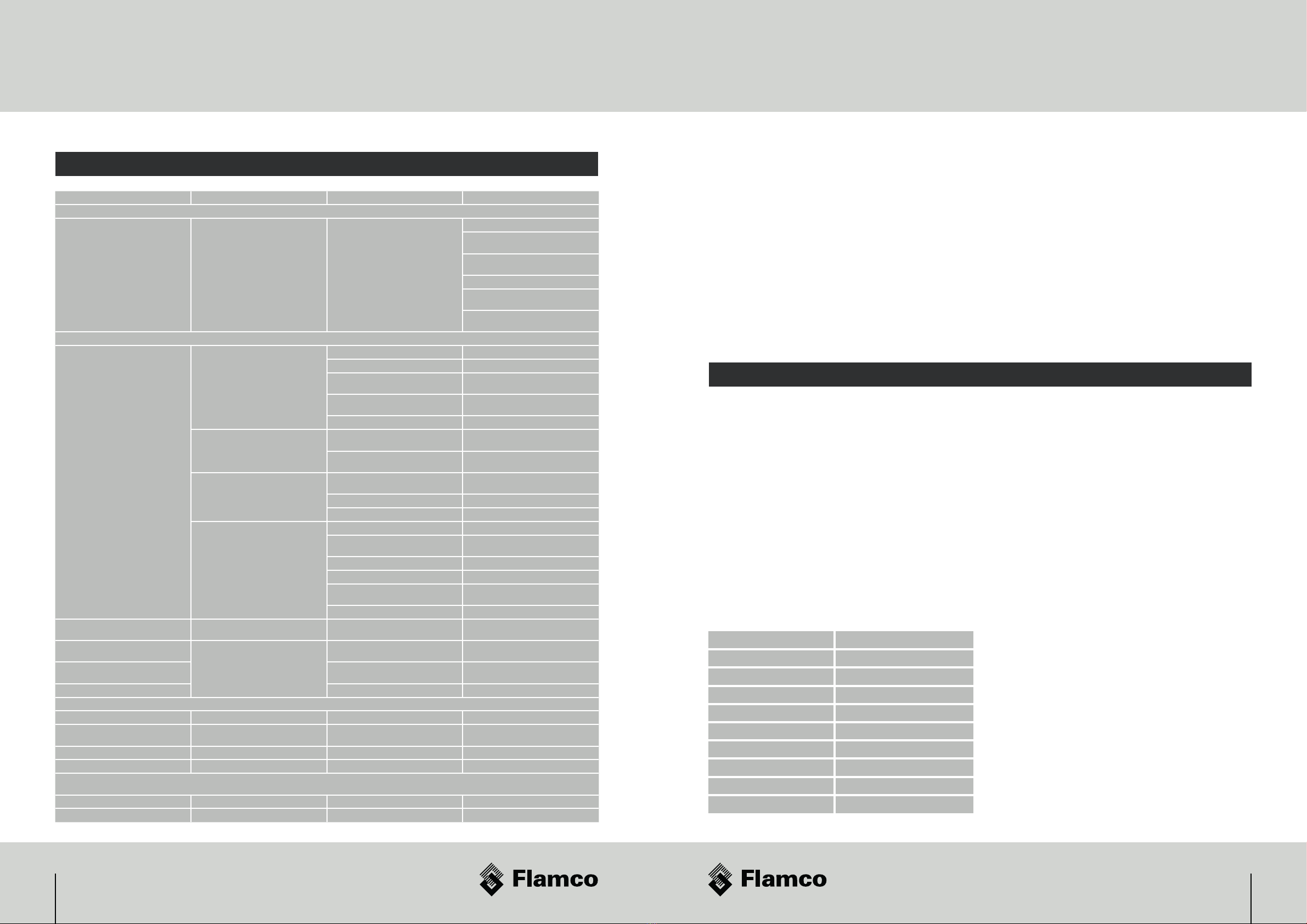
8. Appendix A
# ޔ'/ -.#*0' /*/# - ,0$- ( )/.*!/#
“Operating and Maintenance” instructions handed over with
/# .4./ (ѵ!)1$.*-4./$& -$.+-*1$ 2$/#/# ޔ'/ -$/
should be attached at a suitable location as to indicate the
+- . ) 2$/#$)/# .4./ (*!/# ޔ'/ -/* ).0- + -$*$
checking & servicing by any attending Service Engineer.
2*0''.*- *(( )/#//# . ޔ'/ -.$)*-+*-/
sight glass, particularly on the larger sizes to provide a visual
means of assessing corrosion without the need to disrupt
the operation of the system for checking.
Line Size Magnetic Field Strength
DN15 7500 gauss
DN20 9000 gauss
DN25 10500 gauss
DN35 21000 gauss
DN40 21000 gauss
DN50 52500 gauss
DN80 73500 gauss
DN100 73500 gauss
DN150 94500 gauss

2928
чѵс$)/*-.Ȃ /$)"*--*.$*))4./ (+ -!*-()
• “PH” or relative Acidity/ Alkalinity are of key importance in managing the production of system corrosion. It is
recommended that PH Level of the system water be between 7 and 8.5 (ideally 7.4/7.5). A Lower PH level than
recommended would be classed as acidic and corrode all metals. Alternatively, too high a PH level would be alkaline
and will corrode aluminium components within the wetted part of the system.
• When considering a chemical treatment product to add to the system, we recommend products which incorporate a
($3!*-0Ȃ -$)"Ѷ$)*- -/**)/-*'/# ' 1 '(*- Ȃ /$1 '4ѵ
• Oxygen Ingress should be minimised by the use of closed systems and barrier pipe within the system design.
• ""- ..$1 $*).җ.0#.ޕ03- .$0 .Ҙ+-*(*/ *--*.$*))Ѷ*)/$)0 /**.*0)' ..) 0/-'$. *-ޕ0.# *0/
completely. We would recommend a jointing approach that removes the need to use such compounds and adopt
the use of heat free systems.
• !/-$/$*)'.*' -ޔ//$)".- 0. /# )2 2*0'- *(( )/# 0. *!- *")$. # ($'/- /( )//*ޕ0.#
out and neutralise the system (see section 3.1 below). In addition, it is strongly advised to contact the manufacturer
of the chemical treatment to gain early involvement prior to treatment as to the correct application and chemical to
use.
• The accumulation of sludge & debris can cause deposit corrosion which leads to pitting. We recommend the use
*!- *")$. # ($'/- /( )//*ޕ0.#*0/)) 0/-'$. /# .4./ ()$/$*)Ѷ$/$../-*)"'41$. /*
contact the manufacturer of the chemical treatment to gain early involvement prior to treatment as to the correct
application and chemical to use.
8.3 Refurbishment and Improvement to existing systems
• It is vitally important that before commencing works on existing systems that a complete scan of the water quality
of the system be taken. If it is found that the system contains products of corrosion and/or PH levels in excess
of the required norms, it is recommended that the existing water is conditioned and treated PRIOR to the work
commencing.
8.4 System commissioning (water quality) Water Treatment Chemicals
• *)*/- *(( )/# 0. *!-22/ -!*-#4-0'$/ ./$)"0 /*/# -$.&*!*--*.$*)*!/# 2/ - $)"' ȅ$)
the system and potentially, the internals of the system being exposed to the air due to partial draining.
• # ($''4*. 2/ -.#*0' $)''ޔ''$)"/$1$/$ .$)*-) 2$/#/# # ($'()0!/0- -.ҁ
recommendations and in accordance with BSRIA BG29 2012.
• ȅ -.0$/' ޔ''$)")ޕ0.#$)"- "$( $.0. Ѷ- ' 1)//*/# .4./ ((/ -$'Ѷ''# ($'.0. /* .0$/'
for HIU must comply with EU norms DIN EN 12828 and current guidelines for heating systems. In addition, they
should also be non hazardous, non toxic and biodegradable.
• The use of correct cleaners and inhibitors is of primary, environmental concern. All chemicals used to treat the
system should not contain phosphates, sulphuric acid, nitrites. See BS7593:2006 Code of Practice for treatment of
water in domestic hot water space heating systems.
• Inhibitors should meet Buildcert as a minimum and preferably be recommended by the Energy Savings Trust (ESR).
• Acid based cleaners are unsuitable for older systems as there is a risk of “pinholing” on radiators. They will also
require some form of neutralisation process before being discharged or require being taken away for disposal.
8. Appendix A
8.5 Recommendations for system conditioning - (Basic process)
• # .4./ ((0./ ޕ0.# )$)#$$/ $)*-) 2$/#цфшт)/# *( ./$0$'$)" -1$ .
Compliance Guide.
• The chemicals used should contain the following aspects of their composition:
–Surfactants to reduce surface tension allowing chelating agents to attach to the residues.
–Chelating agents will then entrap the calcium carbonate within the solution.
–Dispersant’s are used to hold residues in suspension.
–The inhibitor then prevents corrosive attacks on metals during cleaning.
–0Ȃ -./*($)/$)) 0/-'ѵ
–Chemicals shall be of a type suitable for disposal through a conventional sewer or foul drain (i.e. no requirement
for tankering or specialist disposal).
–Neutralisation.
–For cooling applications, specialist chemicals and advise should be sought.
8.6 Site installation conditions – Installation of the system
It is recommended that:
–/ -.*'0' ޕ03.#*0' 0. җ)*#'*-$ ҌҘ/# - !*- ҂# /!- ҃.4./ (.- - *(( ) ѵ
–The area of installation should be free from gypsum dust, brick dust, screed or other possible contaminants.
чѵц *(( ) ȅ -- җҘ /2*-&-$(-4.$
• Any relevant details of the installed units and system conditioning to be documented in the O&M manual.
• # - .#*0' ' -)*/$ޔ/$*)*!)4# ($'+-*0/. Ѷ/ . /+' *)/# ѵ
• If there is a requirement for a partial drain down, the inhibitor should be topped up to the required level with full
details.
• #$"#'4- *(( )/#/''. -1$$)"ҝ$).+ /$*) /.+ -()0!/0- -ҁ.$)./-0/$*).җѶޔ'/ -Ѷ# ($'. /Ҙ$.
fully adhered to.
• Any checklist sticker placed within the casing by the manufacturer must be completed.
8. Appendix A

31тп
чѵч *(( ) ȅ -- җ /2*-&Ҙ
It is recommended that a regime of periodic inspection of the system be undertaken. The inspection shall take the form of:
$.0'$).+ /$*)
System visual inspection, exterior corrosion, water stains on the pipe work and equipment, suggesting a slow leak and
make up water entering the system thereby diluting the inhibitor concentrations.
Water Samples
/ -.(+' ..#'' -2)!-*(.0$/' -2*Ȃ+*$)//*. -/$)/# *)$/$*)*!/# ) /2*-&Ѷ*)/# +-$(-4.$
water.
# )'4.$.*!/# 2/ -.#*0'$)'0 ѷ
• Visual assessment – Note any discolouration away from clear as an indicator of possible corrosion
• Chemical assessment – PH value, hardness, precipitate composition and concentration of chemical treatment and type of
treatment contained within the water (A UKAS registered lab is recommended to be used in the system water analysis).
8. Appendix A 8. Appendix B
L2L1 N1 N2
R1 R2 R3
NO C NO C
NO NC C
L N PE
N
L
PE
230V ~
Actuator Head of
pre-payment valve
inside HIU
Fuse
(non switched, 5A)
brown
blue
85 ... 265 V~, 50/60 Hz, 2.5 W, NC
Heat Meter
M-Bus
Pulse
Pulse Inputs
Pulse Output
Pulse Module
M-Bus Module
24 25
2 core cable
230V ~ Module
L
N
PE
01
24 25
2 core cable
01
Example wiring of a pre-payment system (GURU Systems)

3332
8. Appendix C
Spare parts Spare parts
Key Description Detail
1 & 28 Y Strainer G3/4” BT x G3/4” BT L=82 PN20
2 & 20 Temperature sensor NTC 10K3 1/8”BSP ø4.7x17
4 & 5 Pressure test point
6 Spool piece 110mm G 3/4” x G 3/4”
8 & 9 Control valve VDE/ML SIN.ø9.5 24V 50Hz
10 & 12 Plate Heat Exchanger E8LASHx40/1P-SC-S 4xG 3/4”BT
11 & 13 Temperature sensor NTC 10K3 1/8”BSP ø5-6 x 90
14 Over pressure relief valve PRESCOR Rp 1/2” 3 BAR
15 Pressure gauge 0-4BAR / 0-120°C
16 Automatic bleed point MS G3/8” BT
17 Expansion vessel G 3/8” BT 8 LTR
18 Bleed point G 1/8” BT
19 Water hammer arrester G 3/4” WM x G 3/4” BT l=84,5
21 Flow sensor SIKA
22 Non return valve
24 circulation pump, DHW Lowara
25 circulation pump, space heating Grundfos UPM3 AUTO 15-70 130
26 Temperature/pressure sensor RPD 0-6 BAR
27 Drain point
29 & 30 Controller & Power supply
90 $Ȃ - )/$'+- ..0- *)/-*'1'1 2xG3/4”BN 20-60 kPa DN20 PN25
91 #0/*Ȃ1'1 ۔/0/*- R2015-S1 + TRF230NC
92 Seal SENTINEL ø24 x ø16,2 x 3
93 Seal SENTINEL ø29 x ø20 x 2
94 Wall mounting kit (wall plugs, screws,
Washers)
95 & 96 & 97 Heat meter mounting kit
96 & 97 Mounting screw & anti-tampering cap
96 Securing screw ø6
98 EPP case EPP TYPE 9335
99 Steel sleeve White coated
1
94
12
22
164
20
8
29
17
14
18
93
92
25
99
98
95 96 97
19
24
6
91
90
26 21
2
10
30
11
5
9
13 28 27

3534
ContactNotes
United Kingdom
Flamco Limited
Washway Lane
St Helens
Merseyside
WA10 6PB
United Kingdom
+44 1744 744 744
$)!*ҽޕ(*ѵ*ѵ0&
222ѵޕ(*ѵ*ѵ0&

Flamco Limited
Washway Lane
WA10 6PB St. Helens
Merseyside
United Kingdom
T+44 17 447 447 44
F+44 17 447 447 00
E $)!*ҽޕ(*ѵ*ѵ0&
222ѵޕ(*"-*0+ѵ*(
пстфс*"**сҊо)0' -.$*)пфҝршҊ0% //*(*$ޔ/$*).
Table of contents
Other flamco Heating System manuals


Popular Heating System manuals by other brands

Energotech
Energotech EnergoStrip EE-3 Series Mounting and installation

REVENTON
REVENTON INSPIRO Technical documentation

OSTBERG
OSTBERG HERU K Series Assembly and installation instructions

AQUA SZUT
AQUA SZUT TERRAHOT instruction manual

Aqua-Hot
Aqua-Hot 200 Series Use and care guide

International Thermal Research
International Thermal Research CO32D Operator's manual

Airflow
Airflow Uno hab Installation and operating instructions

Danfoss
Danfoss SET2E Installation & user's instructions

Amana
Amana APG14 M Series manual

BLAUBERG Ventilatoren
BLAUBERG Ventilatoren KOMFORT Roto EC S6K 200 user manual

Salda
Salda RIS 700PE EKO 3.0 Technical manual

UTEK
UTEK FLAT GUIDE FOR INSTALLATION, USE AND MAINTENANCE


