flamco Pro PU 131 Manual

© 2018 Flamco group. All rights reserved.
We reserve the right to change designs and technical specifications of our products.
Errors and omissions excepted.
Rev 1.0 Aug-18 Page 1/ 44
Flamco Pro Range Pressurisation Equipment
Pro PU (131, 231, 161, 261, 181, 281)
Pro PUm (131, 231, 161, 261)
Pro PDm (1.0, 1.5, 2.0, 2.5)
Operation & Maintenance Manual

© 2018 Flamco group. All rights reserved.
We reserve the right to change designs and technical specifications of our products.
Errors and omissions excepted.
Rev 1.0 Aug-18 Page 2/ 44
Contents
Customer Details ....................................................................................................................................................... 4
Equipment Details ..................................................................................................................................................... 4
Commissioning Record ..............................................................................................................................................5
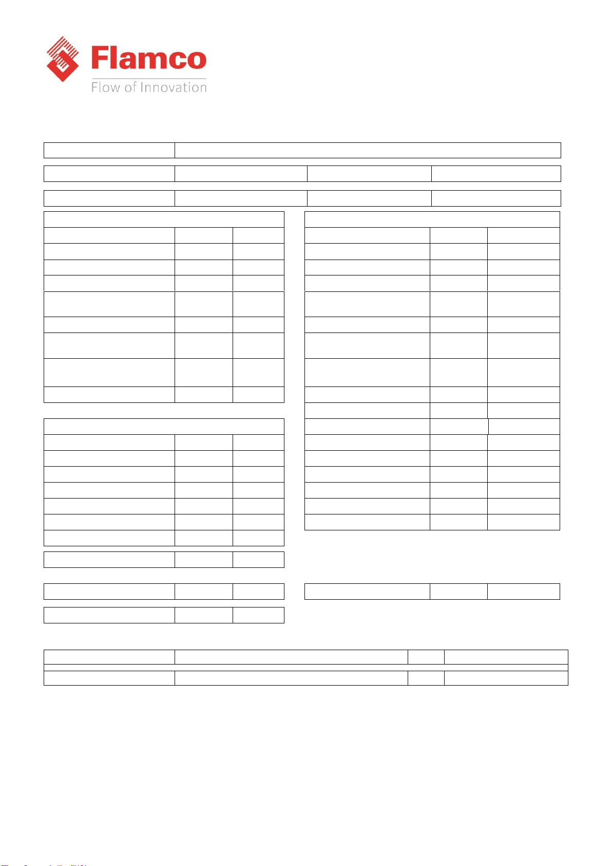
Pressures In A Sealed System.................................................................................................................................... 6
About this Manual..................................................................................................................................................... 7
Conventions used in this Manual .......................................................................................................................... 7
Typography............................................................................................................................................................ 7
Where to find more Information........................................................................................................................... 7
Equipment Overview................................................................................................................................................. 8
Installation................................................................................................................................................................. 9
Pipe Connections................................................................................................................................................... 9
Typical Installation Diagram ..................................................................................................................................9
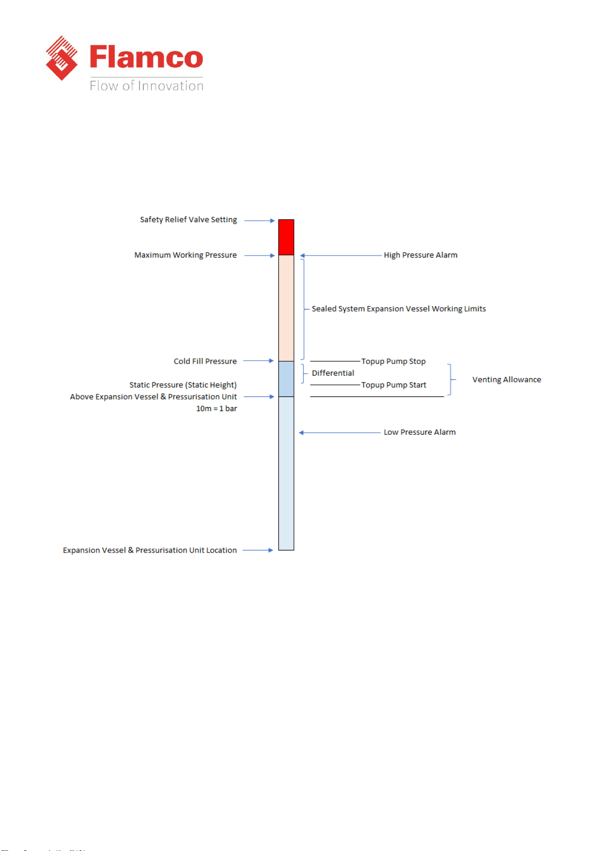
Flow Restrictors (Pro PUm & Pro PDm Only) ......................................................................................................10
Pro PU Clearance and Connection Requirements...............................................................................................11
Pro PUm & Pro PDm Clearance and Connection Requirements .........................................................................12
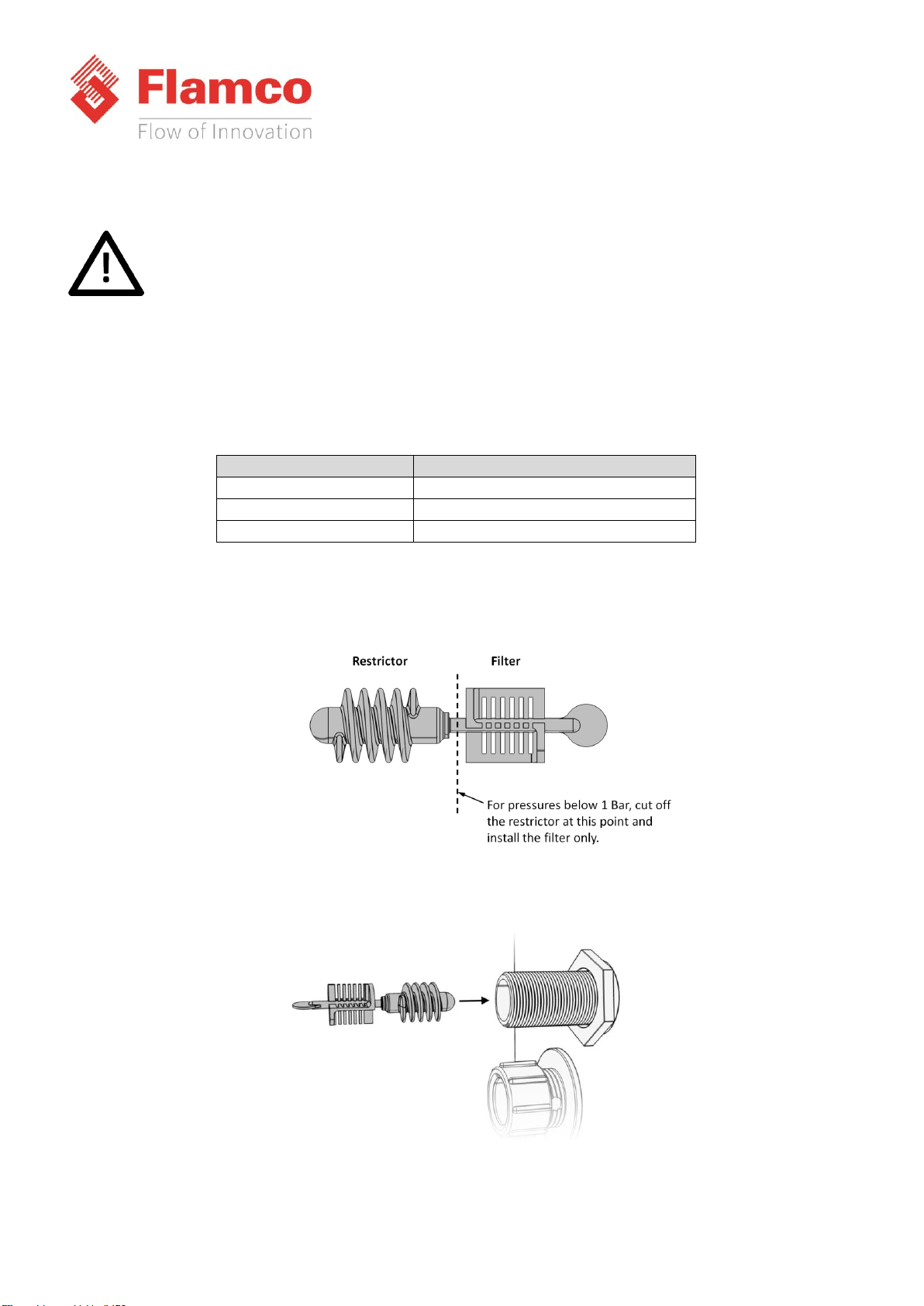
Electrical Power Supply ...........................................................................................................................................13
Micro Controller ......................................................................................................................................................14
Fault contacts ......................................................................................................................................................14
Commissioning ........................................................................................................................................................15
Pre-Commissioning Checklist ..............................................................................................................................15
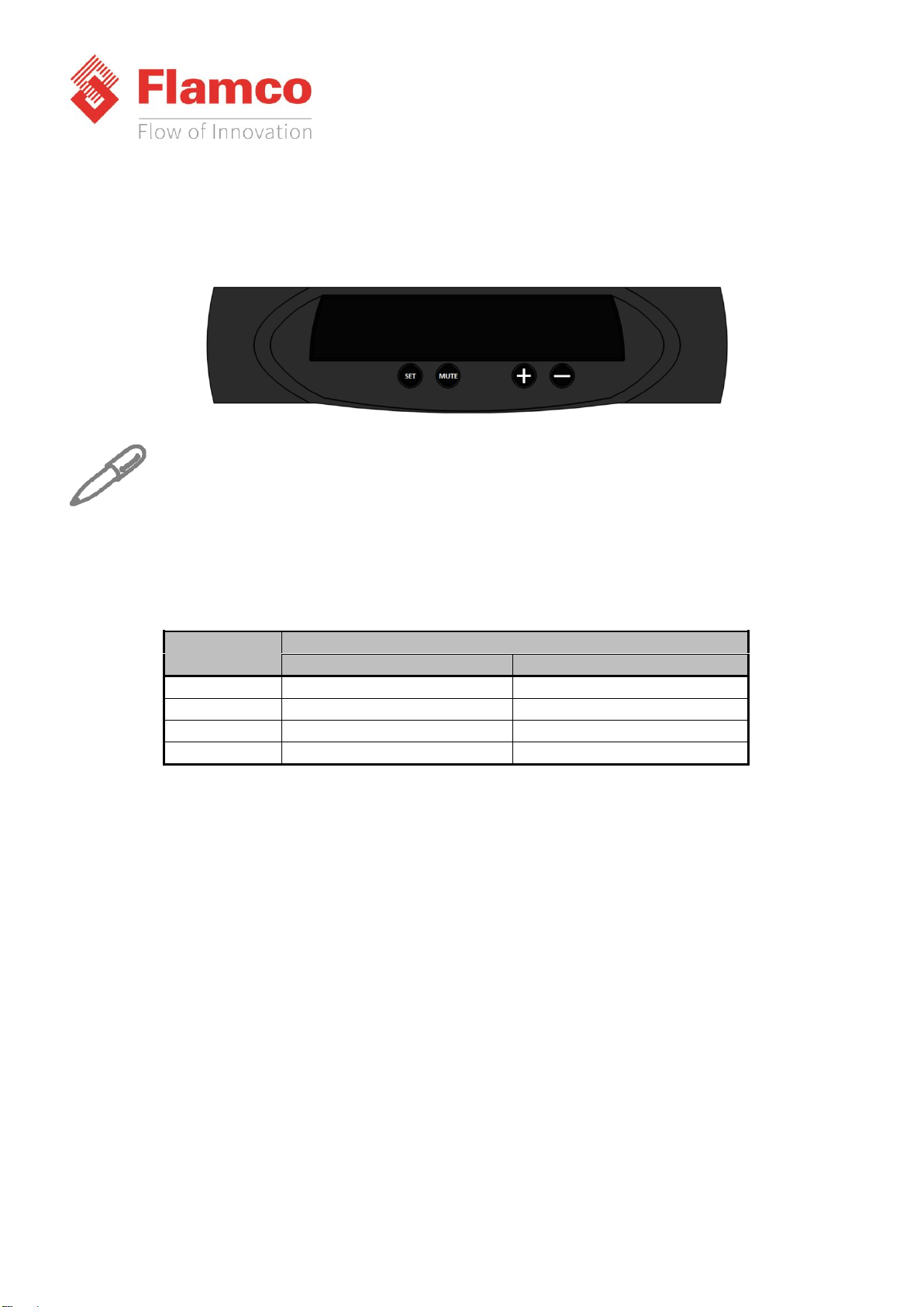
Controller Overview ................................................................................................................................................16
Controller Programming...................................................................................................................................... 17
Program Parameter List...........................................................................................................................................18
Hydraulic Commissioning ........................................................................................................................................21
1. Float Valve Setting........................................................................................................................................... 21
2. Bleeding Pumps ...............................................................................................................................................21
3. Forcing Pumps to Run...................................................................................................................................... 23
4. Initial Start-up..................................................................................................................................................24
5. Testing .............................................................................................................................................................25
Quick equipment suitability guide in relation to system expansion vessel ............................................................ 25
Operation................................................................................................................................................................. 26

© 2018 Flamco group. All rights reserved.
We reserve the right to change designs and technical specifications of our products.
Errors and omissions excepted.
Rev 1.0 Aug-18 Page 3/ 44
Contents
Fault Codes ..........................................................................................................................................................26
Shutdown procedure........................................................................................................................................... 27
Start-up Procedure ..............................................................................................................................................27
Maintenance............................................................................................................................................................28
Visual Inspection..................................................................................................................................................28
Interrogate Controller .........................................................................................................................................28
Test Unit Operation.............................................................................................................................................28
Check Float Valve Operation ...............................................................................................................................29
Check Float Switch Operation .............................................................................................................................29
Check Break Tank Water Condition..................................................................................................................... 29
Check Strainer (Pro PU units only).......................................................................................................................29
Check Expansion Vessel Pre-Charge....................................................................................................................29
Wiring diagram ........................................................................................................................................................ 30
Spare Parts............................................................................................................................................................... 31
Spare kit list –Pro PU ..............................................................................................................................................32
Spare kit list –Pro PUm ...........................................................................................................................................34
Spare kit list –Pro PDm ...........................................................................................................................................35
Troubleshooting ......................................................................................................................................................36
Service Logs .............................................................................................................................................................39
Warranty Details...................................................................................................................................................... 40
Conditions of warranty............................................................................................................................................40
Contact Details.........................................................................................................................................................40
STATEMENT OF COMPLIANCE .................................................................................................................................41
Notes........................................................................................................................................................................42

© 2018 Flamco group. All rights reserved.
We reserve the right to change designs and technical specifications of our products.
Errors and omissions excepted.
Rev 1.0 Aug-18 Page 4/ 44
Customer Details
Please fill in information future reference:
Company: Contact:
Address: Tel No:
Fax No:
Post Code: E-mail:
Equipment Details
Details of model and serial number may be found on the label
Model: Serial No:
Purchase date: Purchase From:
Note:
It is highly recommended to have this equipment commissioned by a Flamco trained engineer. Any damage or
loss incurred through incorrect commissioning by an unapproved engineer will not be covered by the warranty.
If you wish for Flamco to arrange commissioning or service please contact us.
Telephone: +44 (0)1744 744 744
Email: service@flamco.co.uk
Important:
When installing an expansion vessel with the pressurisation unit ensure the expansion vessel gas pre-charge is
the same as the required cold fill pressure for the system.

© 2018 Flamco group. All rights reserved.
We reserve the right to change designs and technical specifications of our products.
Errors and omissions excepted.
Rev 1.0 Aug-18 Page 5/ 44
Commissioning Record
Site Reference
Model
Date
Engineer Name
Company
User PU Settings
Extended PU Engineers Settings
Cold Fill
Bar
Pumps Number
High Alarm Setting
Bar
Pump Type
(C/P/R)
High Pressure Warning
Bar
Pump Sense
(Y/N)
Low Pressure Warning
Bar
Periodic Pulse
(Y/N)
Low Alarm Setting
Bar
Topup Sensor Max
Pressure
Bar
Differential
Bar
Topup Sensor Min Voltage
(2 for MAmp)
Flood Limit
Minutes
Topup Sensor Max Voltage
(10 for
MAmp)
Excessive Start Quantity
(0 to
disable)
Slave Unit (SPC)
(Y/N)
Excessive Start Time
Hours
Additive Unit
(Y/N)
Overrun
Seconds
Counters & Logs
Pressure Alarm Auto Reset
(Y/N)
Pump 1 Count
All VFC - Failsafe
(Y/N)
Pump 1 Hours
Hours
Tank Solenoid
(Y/N)
Pump 2 Count
Tank Solenoid Overrun
Seconds
Pump 2 Hours
Hours
Zero Start
(Y/N)
Alarm Count
Cascade
(Y/N)
Power Interrupted
Extended Mode
(Y/N)
ID Number
Service Reminder
(Y/N)
Expansion Vessel Volume
litres
Gas Pre-Charge
bar
Safety Relief Valve Setting
bar
Engineers Signature
Date
Customers Signature
Date

© 2018 Flamco group. All rights reserved.
We reserve the right to change designs and technical specifications of our products.
Errors and omissions excepted.
Rev 1.0 Aug-18 Page 6/ 44
Pressures in a sealed system
Below is an overview of how the settings on a pressurisation unit must be considered for normal operation.
Close, conflicting or overlapping settings will cause system instability and nuisance alarm conditions. If in any
doubt please seek advice from a Sealed System professional.
A typical venting allowance is 0.3 bar, added to the static height to give the cold fill pressure.
The Differential setting represents the allowable pressure loss before the pump activates and restores the cold
fill pressure. The Differential setting must not be greater than the system venting allowance. This will ensure
that the system remains fully flooded during normal topup conditions.

© 2018 Flamco group. All rights reserved.
We reserve the right to change designs and technical specifications of our products.
Errors and omissions excepted.
Rev 1.0 Aug-18 Page 7/ 44
About this Manual
This Operation and Maintenance Manual contains all the necessary information to install, commission, operate
and maintain Flexfiller pressurisation equipment.
It is recommended to read all parts of this manual before undertaking any work on the equipment.
Conventions used in this Manual
This manual makes use of symbols to identify key pieces of information. Please take note of the following
symbols and their meaning:
DANGER –Important safety related information intended to prevent injury and/or damage to the
equipment, system or property.
CAUTION - Important information intended to prevent damage to the equipment, system or
property.
IMPORTANT - Important information intended to ensure that the equipment functions correctly.
USEFUL –Useful information which may be helpful, but is not necessarily required for the unit to
function correctly.
Typography
This manual makes use of different typography to identify different types of information.
Italics Key words and phrases
(Round Brackets) Used to identify a button on the digital controller
[Square Brackets] A parameter on the digital controller
<Inequality Symbols> A message/fault code displayed on the digital controller
Where to find more Information
For further information please visit the Flamco Limited Website at the following URL:
https://flamcogroup.com/uk-en
Alternatively, please contact the Flamco Limited office using the details below:
Phone: 01744 744 744
Fax: 01744 744 700

© 2018 Flamco group. All rights reserved.
We reserve the right to change designs and technical specifications of our products.
Errors and omissions excepted.
Rev 1.0 Aug-18 Page 8/ 44
Equipment Overview
The function of this pressurisation unit is to provide a means of automated water top-up to sealed heating and
cooling systems. The equipment is designed to provide periodic water top-up to compensate for minor losses in
system pressure (e.g. slow leaks, air venting, etc.).
This equipment is not designed to cope with sudden losses of system pressure (e.g. manual
draining) or major water losses (e.g. large leaks). The equipment is also not intended to be used
for water boosting applications.
Principal of Operation
The following schematic shows the internal arrangement of a pressurisation unit:
The pressurisation unit is fitted with a break tank (1) which is filled from the mains water supply (2) via a float
operated valve (3). The break tank is fitted with a warning overflow (4) in case the break tank overfills, and a
weir overflow (5) as the primary backflow protection.
The pressurisation unit is connected into the heating system (6) via an isolation valve (7).
The pressure sensor (8) monitors the system pressure.
If the pressure sensor detects a drop in pressure, the pump (9a) will pump water from the break tank into the
system. Once the required pressure has been reached, the pump will stop.
On twin pump models, a second pump (9b) is provided. The two pumps will run in a duty/standby/automatic
changeover configuration (i.e. the active pump will alternate with each pump start).
The pump(s) are fitted with non-return valves (10a, 10b) to prevent backflow.
A drain valve (11) is provided for draining down the unit and for commissioning purposes.

© 2018 Flamco group. All rights reserved.
We reserve the right to change designs and technical specifications of our products.
Errors and omissions excepted.
Rev 1.0 Aug-18 Page 9/ 44
Installation
This pressurisation unit is not designed to be installed in an outdoor environment. The unit must
be installed in a frost free environment, away from precipitation and water sprays/jets. If there is
a risk of flooding, the unit must be installed on a raised plinth.
The unit is equipped with a Category 5 Weir overflow arrangement and must not be installed /
sited where damage to the local environs can occur on water egress
Please refer to the appropriate datasheet for the maximum working pressure and temperature of
the pressurisation unit. The conditions at the point of connection to the system must not exceed
these values.
Pipe Connections
To avoid damaging the float valve, the mains water supply pipe must be flushed before
connection to the pressurisation unit.
All pipe connections must be made with appropriate jointing compound/PTFE tape.
If PTFE tape is used, care must be taken to ensure that the tape does not obstruct the orifice of
the fitting.
Non-return valves, pressure reducing valves and RPZ valves must not be installed between the
pressurisation unit and the heating/cooling system. These devices will prevent the pressure
sensor from reading the system pressure.
The pressurisation unit and expansion vessel should be connected to the system at the same
point, to provide a neutral pressure reading. This point of connection should be in the system
return, on the suction side of the circulation pump.
Typical Installation Diagram

© 2018 Flamco group. All rights reserved.
We reserve the right to change designs and technical specifications of our products.
Errors and omissions excepted.
Rev 1.0 Aug-18 Page 10 / 44
Flow Restrictors (Pro PUm & Pro PDm Only)
Pressurisation equipment fitted with a plastic, side-entry torbeck valve must be fitted with a filter
and –depending on the mains water pressure –a flow restrictor. Failure to do this may result in
damage to the equipment.
Two different flow restrictors are supplied with the equipment, both of which include an integral filter. The
selection of the appropriate flow restrictor is based on the maximum mains water pressure at the point of
installation. Please refer to the following table for selection.
Mains Water Pressure
Requirement
Below 1 Bar
No Restrictor. Install Filter Only
1 –4 Bar
Low Pressure Restrictor (coloured)
Above 4 Bar
High Pressure Restrictor (white)
If no restrictor is required, the filter must be removed from one of the restrictors and installed on its own. The
following diagram shows how to remove the filter:
To install the flow restrictor/filter, hold it by the tab and push it into the opening of the float valve connection,
as shown in the diagram below:

© 2018 Flamco group. All rights reserved.
We reserve the right to change designs and technical specifications of our products.
Errors and omissions excepted.
Rev 1.0 Aug-18 Page 11 / 44
Pro PU Clearance and Connection Requirements –Floor Standing unit
Connection
Size
Notes
Mains
Water Feed
½” BSP M
An isolation valve must be
installed on the mains water feed
for servicing.
Break Tank
Overflow
22 mm
Guidance on drainage
requirements should be obtained
from the local water authority.
System
Connection
½” BSP M
/ 15mm
The pressurisation unit and
expansion vessel should be
connected to the system at the
same point.
The point of connection should
be in the system return, on the
suction side of the circulation
pump.
Non-return valves, pressure
reducing valves and RPZ valves
must not be used.

© 2018 Flamco group. All rights reserved.
We reserve the right to change designs and technical specifications of our products.
Errors and omissions excepted.
Rev 1.0 Aug-18 Page 12 / 44
Pro PUm & Pro PDm Clearance and Connection Requirements –Wall mounted
Connection
Size
Notes
Mains
Water Feed
½” BSP M
An isolation valve must be
installed on the mains water
feed for servicing.
Break Tank
Overflow
22 mm
Guidance on drainage
requirements should be
obtained from the local water
authority.
System
Connection
½” BSP M
/ 15mm
The pressurisation unit and
expansion vessel should be
connected to the system at the
same point.
The point of connection should
be in the system return, on the
suction side of the circulation
pump.
Non-return valves, pressure
reducing valves and RPZ valves
must not be used.

© 2018 Flamco group. All rights reserved.
We reserve the right to change designs and technical specifications of our products.
Errors and omissions excepted.
Rev 1.0 Aug-18 Page 13 / 44
Electrical Power Supply
This equipment must be electrically isolated before removing the covers. Cables connected to the
volt free contacts may be supplied from another source and may remain live after the unit is
isolated. These must be isolated elsewhere.
All electrical connections must be carried out by a suitably qualified and competent person.
The mains power supply to the pressurisation unit must be connected into the fused terminal block as shown
below:
On some larger models, the fused terminal block is replaced by a fused spur. If this is the case, the power supply
must be connected into the fused spur, as shown below:
It is recommended to supply power to the pressurisation unit via a lockable isolator. This should
be installed within 2 m of the equipment.
This equipment can be damaged by the high voltages produced by electrical installation testing
equipment. When performing electrical installation tests, the equipment must be isolated from
the supply.

© 2018 Flamco group. All rights reserved.
We reserve the right to change designs and technical specifications of our products.
Errors and omissions excepted.
Rev 1.0 Aug-18 Page 14 / 44
Micro Controller
Fault contacts
There are 6 volt free fault contacts which can be used for connection to a BMS system, located on terminals 1-
12 on the digital controller.
With the exception of the Common Alarm, it is possible to convert all other fault contacts to
normally closed. For further information please refer to the commissioning section of this manual.
The other volt free contacts can be connected to the BMS and when the alarm is triggered this is
shown on the Pressurisation unit and the BMS.

© 2018 Flamco group. All rights reserved.
We reserve the right to change designs and technical specifications of our products.
Errors and omissions excepted.
Rev 1.0 Aug-18 Page 15 / 44
Commissioning
It is highly recommended to have this equipment commissioned by a Flamco approved engineer.
Any damage or loss incurred through incorrect commissioning by an unapproved engineer will not
be covered by the warranty.
Pre-Commissioning Checklist
The following conditions must be met before starting the commissioning process. Failure to meet
these conditions may result in injury or damage to the equipment, system and property.
Equipment is sited in a frost free area, away from precipitation and water sprays/jets
All necessary pipe/electrical connections have been made to a satisfactory standard
The temperature and pressure at the point of connection are within the operating limits of the
pressurisation unit.
The heating/cooling system is fitted with a safety valve and expansion vessel
The following conditions must be met for the pressurisation unit and heating/cooling system to
function correctly. If these conditions have not been met, it is not advisable to proceed with the
commissioning process.
The system connection has been made into the system return header / pump suction
There are no non-return valves, pressure reducing valves or RPZ valves installed between the
pressurisation unit and the heating/cooling system
The expansion vessel is pre-charged to the correct pressure (equal to PU cold fill pressure)
It is advisable to fill the heating/cooling system prior to commissioning. If this is not possible, the
pressurisation unit can be used to fill the system after commissioning (Not possible with Mini
Units). Depending on the size of the system, this may take a considerable amount of time.
The heating/cooling system is filled and pressurised to the required cold fill pressure, with the water at
ambient temperature (approximately).

© 2018 Flamco group. All rights reserved.
We reserve the right to change designs and technical specifications of our products.
Errors and omissions excepted.
Rev 1.0 Aug-18 Page 16 / 44
Controller Overview
The following image shows the front of the pressurisation unit digital controller. 4 buttons are provided for
programming, and an LED display which shows scrolling messages.
When the controller is first powered up, it will display the controller version number. This manual
relates to controller version >10.0. If the controller is of a different version, there may be
differences in the menu items available.
When in normal operation, the controller will display the current system pressure. If a fault occurs, the
controller will display a fault code and produce an audible alarm.
In normal operation, the functions of the buttons are as follows:
Button
Function
Press
Hold
SET
-
Show Current System Pressure
MUTE
Mute Audible Alarm
Reset Unit
+
-
Enter Programming Menu
-
-
Enter Programming Menu

© 2018 Flamco group. All rights reserved.
We reserve the right to change designs and technical specifications of our products.
Errors and omissions excepted.
Rev 1.0 Aug-18 Page 17 / 44
Controller Programming
Do not alter any settings without first understanding the implications of doing so. Incorrect
settings may cause damage to the equipment, wider system or property.
To enter the programming menu, hold the (+) button until “enter code” appears on the screen, followed by
“9999” with a flashing cursor after the first digit.
To gain access to the programming menu, one of the following codes must be entered:
Standard Code
Standard set of options
2601
Engineer Code
Full set of options
4706
To enter the code, change the first digit with the (+) and (-) buttons, then press (SET) to move onto the next
digit. Repeat for all digits, then once the correct code is shown on the display, press (SET) to enter the
programming menu.
Once a correct code has been entered, the first option PR00 –Language will appear select E and then press and
hold (SET) & (+) to move to next menu.
Once in the menu, the value of the current menu item can be changed using the (+) and (-) buttons. Once the
current value has been set, pressing the (SET) & (+) buttons together to move to the next option or (SET) & (-)
buttons together to move back an option is you made an error.
Once the programming is complete press and hold the (SET) button for few seconds to save the settings.
If the controller loses power while in the programming menu, all changes made up to that point
will be erased. To confirm all changes, the end of the menu must be reached, and press and hold
the (SET) button for few seconds to save the settings
Key:
(SET) & (+) = Move to next menu
(SET) & (-) = Move back to pervious next menu
Hold down (SET) = Hold (SET) button down for few seconds saves the menu

© 2018 Flamco group. All rights reserved.
We reserve the right to change designs and technical specifications of our products.
Errors and omissions excepted.
Rev 1.0 Aug-18 Page 18 / 44
Program Parameter List
The table below gives details of all menu items, in the order that they will appear:
PR No
Customer Code - 2601
Notes
Default
Unit
0
Language
E=English I=Italian D=Deutsch F=French
N=Netherland
E
2
Low Pressure Alarm
0.5 bar less than Fill Pressure
0.5
Bar
STANDARD OPTION
3
Low Pressure Warning
0.6 Bar less than Fill Pressure
0.6
Bar
4
Differential
‘cut-in’ and ‘cut-out’ between pumps
0.2
Bar
5
Fill Pressure
System pressure + 0.3 venting
allowance
1
Bar
6
High Pressure Warning
High pressure alarm –0.1 Bar
2.6
Bar
7
High Pressure Alarm
System safety valve - 10%
2.7
Bar
8
Flood Limit
10
minutes
9
Excessive Start Quantity
0
10
Excessive Start Time
8
hours
28
Fill system
N
45
Service Reminder Y/N
N
48
ID Number
MODBUS ID number
1
49
Review Logs
N
50 (*)
Counter for P1 used for Topup
51 (*)
Hours Run for P1 Topup
52 (*)
Counter for P2 used for Topup
53 (*)
Hours Run for P2 Topup
54 (*)
Total Hours run P1 (inc Degassing)
55 (*)
Total Hours run P2 (inc Degassing)
56 (*)
Alarm Counter
57 (*)
Power interrupted counter
(*)
IF REVIEW LOG IS YES THEM PR NUMBER 50 - 57 WILL BE ACTIVE
This menu only brings up standard option for the pressurisation equipment, to set up the degasser option of the
equipment then you need to put in 4706 code and follow the menu list on the next pages.

© 2018 Flamco group. All rights reserved.
We reserve the right to change designs and technical specifications of our products.
Errors and omissions excepted.
Rev 1.0 Aug-18 Page 19 / 44
This menu is for setup combine unit in order the menu will appear:
PR No
Engineers Code - 4706
Notes
Default
Unit
-
Language
E=English I=Italian D=Deutsch F=French
N=Netherland
E
1
Topup Required Y/N
Y
TOP-UP MENU
2
Low Pressure Alarm
Dependent on sensor range data
0.5
Bar
3
Low Pressure Warning
Dependent on sensor range data
0.6
Bar
4
Differential
+/- of cold fill pressure
0.2
Bar
5
Fill Pressure
system pressure + 0.3 vent allowance
1
Bar
6
High Pressure Warning
set 0.4 below the safety valve on
installation
2.6
Bar
7
High Pressure Alarm
Set 0.3 below the safety valve on
installation
2.7
Bar
8
Flood Limit
10
minutes
9
Excessive Start Quantity
0
10
Excessive Start Time
8
hours
11
Pump Number
1
STANDARD OPTION
12
Pump Type
Pump Type C (current monitored
centrifugal pump)
C
Pump Type P (current monitored Piston
pump)
Pump Type R (Not Current Monitored,
larger pump/motor contactor etc)
13
Pump Current Min Level
0.2
mA
14
Current Sense
Y
15
Periodic Pulse
Y
16
Pressure Sensor Max
Pressure
10
Bar
17
Pressure Sensor Min
Voltage
1
Volts
18
Pressure Sensor Max
Voltage
6
Volts
19
Slave Unit
SPC Mode, high water switch activates
pumps
N
20
Additive Unit
Changes High Water Message if not in
(Slave/SPC mode)
N
21
Overrun
Pump Overrun after achieving set
pressure (or Slave/SPC command is
deactivated)
5
Seconds

© 2018 Flamco group. All rights reserved.
We reserve the right to change designs and technical specifications of our products.
Errors and omissions excepted.
Rev 1.0 Aug-18 Page 20 / 44
PR No
Engineers Code - 4706
Notes
Default
Unit
22
Pressure Alarm Auto
Reset
Toggles High/Low Alarm from being
automatic reset to manual reset/critical
stop
Y
STANDARD OPTION
23
All VFC Fail Safe
Toggles all VFC alarms to be energised,
normally closed. Break/open on fault
N
24
Tank Solenoid
Uses High Water contact to activate a
tank topup solenoid
N
25
Tank Solenoid Overrun
Overrun command for filling solenoid
5
Seconds
26
Zero Start
Allows topup unit to start immediately if
switched on and seeing 0 bar (formerly
boost option)
N
27
Cascade
Delay start time for activating both
pumps together [note 0 means that the
pumps will NOT run together, but
operates as duty/standby/auto change
over
0
Seconds
{disabled}
28
Fill system
N
29
Extended Mode
N
30
not used
N
31
Degassing Required Y/N
N
45
Service Reminder Y/N
N
46
Pump1 Max Hours Run
Alarm to change Pump
9000
Pump
(when set to 0 the alarm is disabled)
47
Pump 2 Max Hours Run
Alarm to change Pump
9000
(when set to 0 the alarm is disabled)
48
ID Number
MODBUS ID number
1
49
Review Logs
N
REVIEW LOG MENU
50 (*)
P1 Topup Count
Counter for P1 used for Topup
51 (*)
P1 Topup Hours
Hours Run for P1 Topup
52 (*)
P2 Topup Count
Counter for P2 used for Topup
53 (*)
P2 Topup Hours
Hours Run for P2 Topup
54 (*)
P1 Total Hours
Total Hours run P1 (inc Degassing)
55 (*)
P2 Total Hours
Total Hours run P2 (inc Degassing)
56 (*)
Alarm Count
Alarm Counter
57 (*)
Power Interrupted
Count
Power interrupted counter
This manual suits for next models
13
Table of contents
Other flamco Heating System manuals
Popular Heating System manuals by other brands

Artek
Artek SANAGA TECK Assembly and operating manual

Vectaire
Vectaire EVO220DC Installation, operating and maintenance instructions

ensto
ensto TASSU Installation instruction

Baxi
Baxi GAVINA 20 GT Operation, Cleaning and Maintenance Instructions for the USER

Greenie HEAT
Greenie HEAT PGHG600W User instruction manual

NuAire
NuAire MRXBOX95-LH2 datasheet

Salda
Salda RIS 200VE EKO Technical manual

AKO
AKO 70130 Application Instructions

Bradford White
Bradford White LAARS MASCOT LX Startup guide

DEVI
DEVI Devifoil Mirror installation instructions

Seeley
Seeley AIRA ATH Series Installation, operation & service manual

Ducoterra
Ducoterra Sola Ray II Important instructions