Flexball 4000-ELT User manual

Flexball Italiana S.r.l. 1
O
Op
pe
er
ra
at
ti
in
ng
g
m
ma
an
nu
ua
al
l
&
&
m
mo
ou
un
nt
ti
in
ng
g
i
in
ns
st
tr
ru
uc
ct
ti
io
on
ns
s

Flexball Italiana S.r.l. 2
Index
1. Introduction ....................................................................................................................................... 3
2. General installation features .............................................................................................................. 3
2.1. Description of the system and its parts .................................................................................. 3
2.2. Maximum extension of the system......................................................................................... 3
2.3. Specification ......................................................................................................................... 3
3. Pilot instructions ................................................................................................................................ 4
3.1. Control keypad...................................................................................................................... 5
3.2. Acquisition of the command .................................................................................................. 6
3.5 Fast Start-up Mode ................................................................................................................... 6
4. Command station .............................................................................................................................. 6
4.1. Dimensions........................................................................................................................... 6
4.1.1. Command station series 4000........................................................................................... 6
4.1.2. Command station series 4500........................................................................................... 7
4.2. Friction adjustment................................................................................................................ 7
4.2.1. Command station series 4000........................................................................................... 7
4.2.2. Command station series 4500........................................................................................... 8
4.3. Command station set-up ....................................................................................................... 8
6. Accessories and option...................................................................................................................... 9
6.1. Power supply and speed reference cable (4 poles)................................................................ 9
6.6. T-Splitter............................................................................................................................. 10
6.9. Command cable (4 poles) ..................................................................................................... 11
8. Interface towards the motor controller and functioning principle........................................................ 12
8.1. Speed signal towards the motor’s controller .......................................................................... 13
8.2. Programming of the delay when passing from Forward to Reverse or vice versa ................... 13
8.3. CanBUS protocol .................................................................................................................. 13
8.4. Technical data of the CANBus interface card ........................................................................ 13
21. Behaviour of the electronic system in case of failures ...................................................................... 14
21.4. Troubleshooting .................................................................................................................. 14
21.5. LED diagnosis on command station .................................................................................... 14
23. Drilling mask for command station ................................................................................................... 15
Version July 2013
Flexball Italiana S.r.l. 3
1. Introduction
This manual describes the electronic remote control system in general and its operating, performance and
safety aspects. If it is the first time that you install an electronic control system, go to section 22 where you
will be guided to the necessary steps.
2. General installation features
2.1. Description of the system and its parts
The electronic systems 4000 – ELT and 4500 – ELT are composed with the lever and the necessary cables
for the connection to the motor’s controller.
2.2. Maximum extension of the system
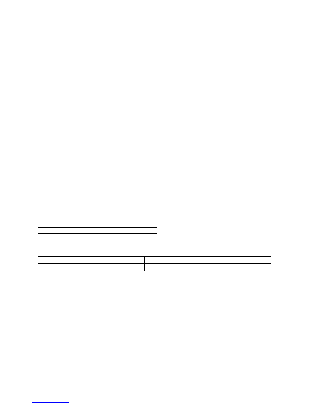
The maximum configuration of the system is as shown in the following table:
10 meters
Maximum distance between
lever
and engine room
in c
ase of voltage
interface towards the motor controller
80 meters
Maximum distance between
lever
and engine room
in case of CANBus
interface towards the motor controller
2.3. Specification
Temperature
Operating temperature
From
-
10 to 85°C
Storage temperatur
e
From
-
40 to 90°C
Electrical features
Power supply (*) From 9,0 to 28,0 Vdc
Max. current absorbed 0,5 A
Flexball Italiana S.r.l. 4
3. Pilot instructions
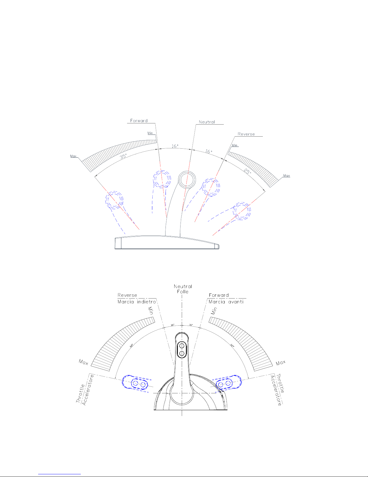
Each station can be programmed for the control of one engine. Each lever repeats the functionality of a
traditional mechanical lever.
Moving the lever from the neutral position, after 16°forward or reverse automatically the electronic system
clutches-in respectively the forward or reverse gear. The accelerator lever has a stroke of 35° in forward
direction and 25°in backward direction.
Command station series 4000
Command station series 4500
Flexball Italiana S.r.l. 5
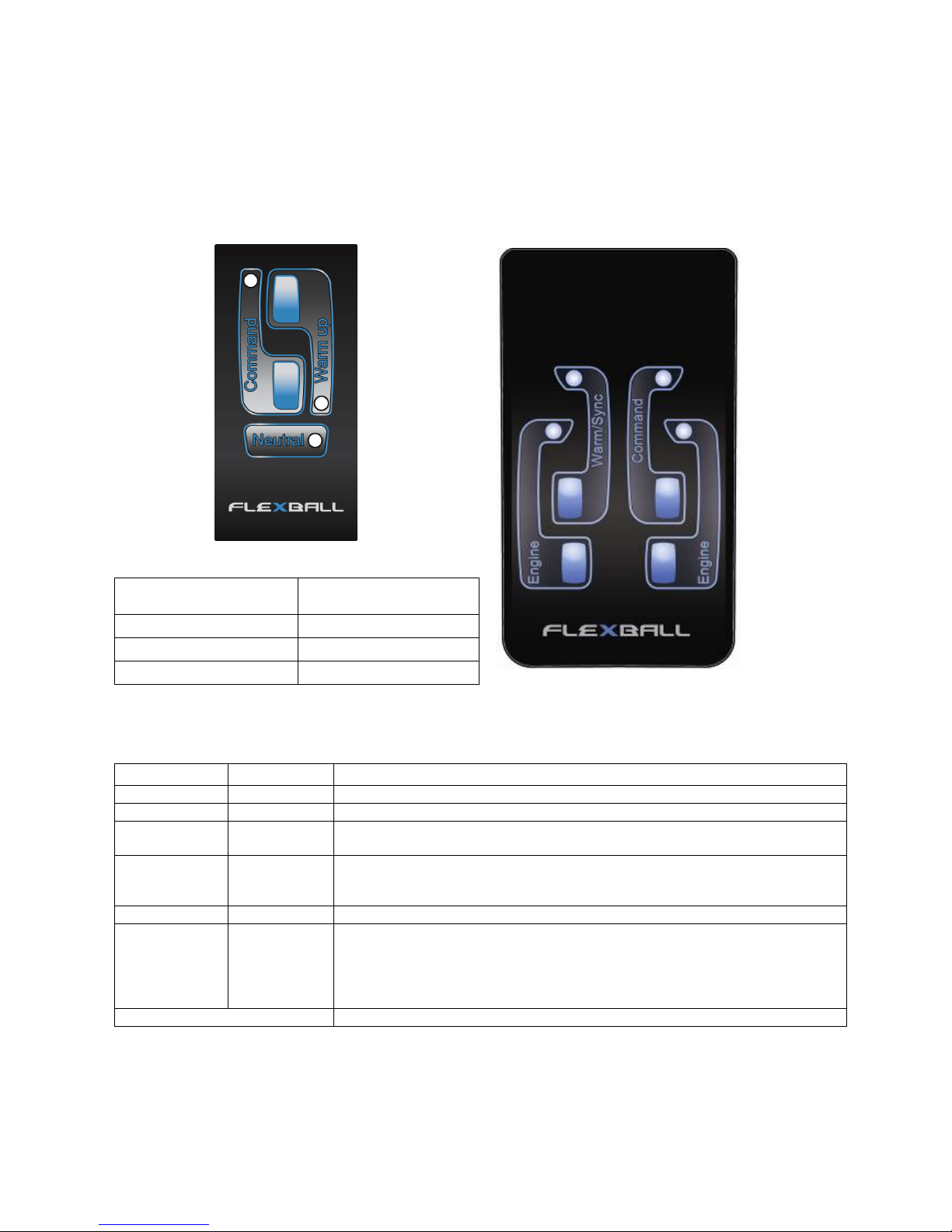
3.1. Control keypad
On the command station it is mounted an electronic keypad with 2 push-buttons and 3 LEDs.
It follows the table with the definition of LED and push buttons.
Push-button LED Description
(Command)
(Meaning)
Engine
If the LED has a fixed ligh
t on (green), the
gearbox is in neutral position.
Command
I
f it is switched off, the Station has not the command.
If is switched on, the Station has the command.
Warm up
If it is blinking, the navigation system is in Warm
-
up mode; this means that
the engines can be warmed up without clutching-in the gear.
If the LED is fix lighted, the system is in Synchro mode
Warm up
Not in use for this application
Command
If you press Command for 1,5 seconds the station takes the command, only
if one of these two conditions are respected:
- after power up lever is in neutral
- the lever is synchronized with respect to the lever of the station that at the
moment has the command
All LEDs are lighted on The control system isn’t working correctly
Description LEDs colour
Engine Green
Warm/Sync Orange
Command Red
Command station series 40
00
Command station series 4500
Flexball Italiana S.r.l. 6
3.2. Acquisition of the command
It is possible to acquire the command of the boat from any Station in the following cases:
1. Position the lever in neutral and press Command for 1,5 seconds.
►Important: before taking the command, proof that all the passengers are safely on board.
3.5 Fast Start-up Mode
This function is available on the first command station as described in section 8.1 of this manual. When the
configuration FSM (Fast Start up Mode) is enabled, the command station with the FSM enabled takes
automatically the command at the power on, only if this command station is in neutral position.
If the command station is not in neutral position, the command station will take the command as soon the
neutral position will be reached.
4. Command station
Command stations are classified as devices for the control of the engine. Up to three command stations
can be mounted in the same installation. Depending on the application, it is very important to set the dip-
switches present on the bottom part of the command station, as described in sections 4.2 and 8.1 of this
manual.
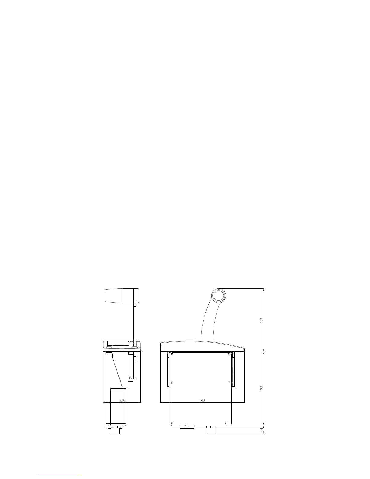
4.1. Dimensions
4.1.1. Command station series 4000
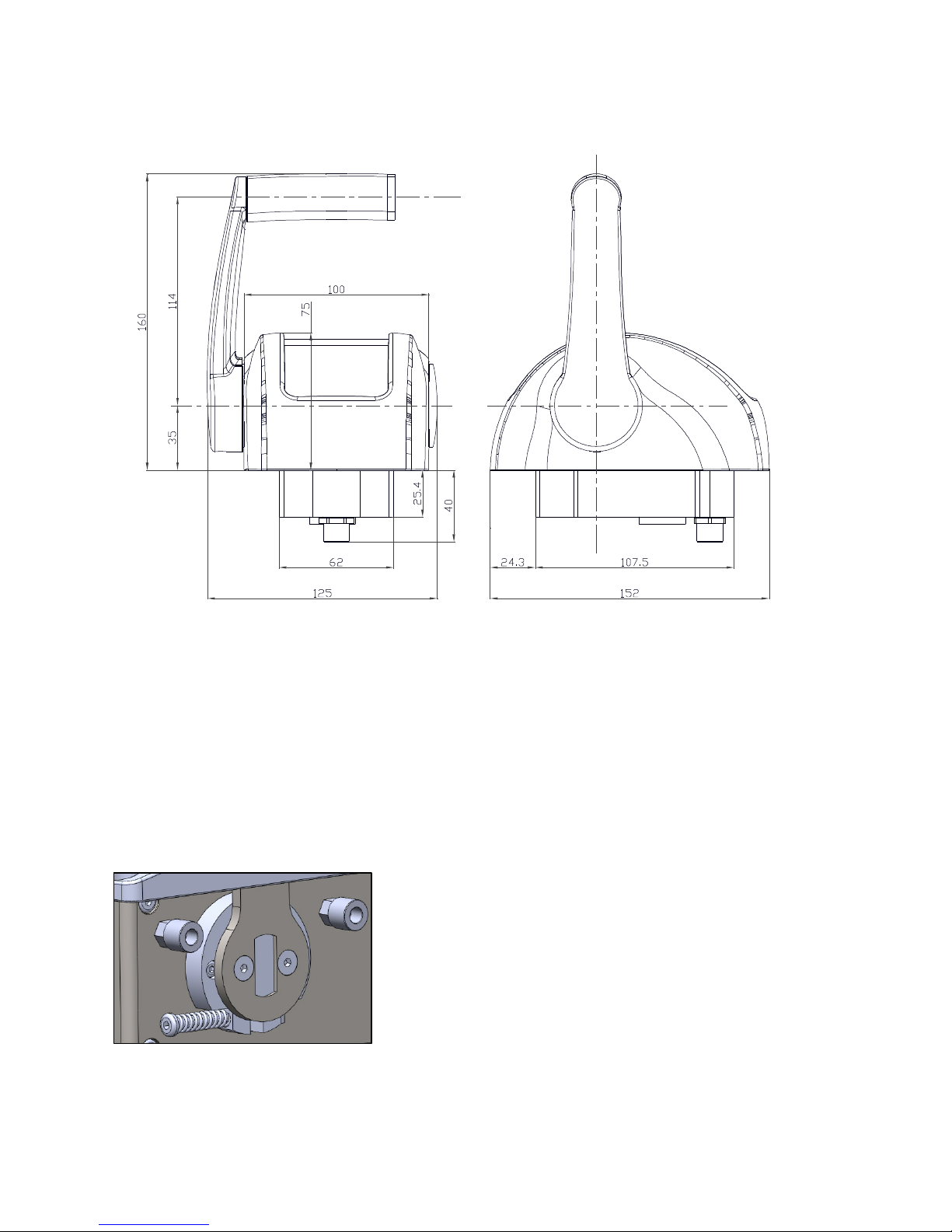
Flexball Italiana S.r.l. 7
4.1.2. Command station series 4500
4.2. Friction adjustment
4.2.1. Command station series 4000
In order to adjust the friction of the lever, it is enough to tune the
screw that you can find just behind the control lever, as shown in
the picture on the left. With an hexagon screw driver size 2,5 mm
you can loosen or tighten the screw and the friction will become
correspondingly softer or harder.

Flexball Italiana S.r.l. 8
4.2.2. Command station series 4500
In order to adjust the friction of the lever, it is necessary to remove the screw A
placed below the plastic base of the command station. With the help of an
hexagon screw driver size 3 mm you can loosen or tighten the screw and the
friction will become correspondingly softer or harder.
Once the friction has been adjusted, close again the hole with screw A.
Important: In case of a command station for single engine, the friction is present
only on the left lever.
4.3. Command station set-up
Under the base of the command station there is a plastic cap. Unscrewing it, you can access to the dip-
switches.
Operation:
•unscrew the plastic cap;
•set the dip-switch position according to the following table;
•screw again the cap.
Under the base of the command station it is present the
following label.
This labels indicates the code of the command station, the
serial number and the different dip-switches configuration
according to the type of the command station.
Dip-switch 1
It defines how you want to setup your electronic control lever
•OFF: standard start-up mode at power up (see
section 5.xx)
•ON: Fast Start-up Mode at power up (see section
5.xx)
Dip-switch 2
Available for further developments
Dip-switches 3 and 4
Identify the delay time between forward reverse commands (inversion of direction)
Dip
-
switch 3
Dip
-
switch 4
No delay during inversion of direction OFF OFF
Delay of 1 second during inversion of direction OFF ON
Delay of 2 seconds during inversion of direction ON OFF
Delay of 4 seconds during inversion of direction ON ON
Flexball Italiana S.r.l. 9
6. Accessories and option
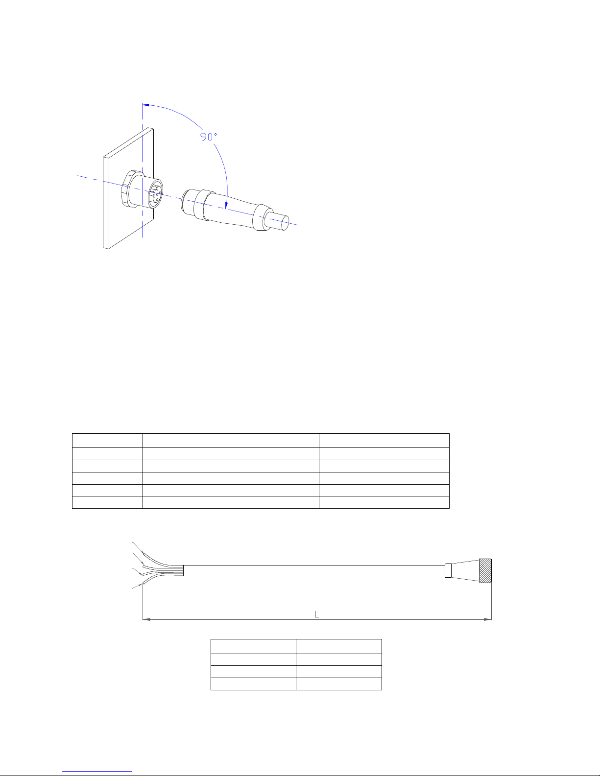
Extreme care must be paid during electrical
installation of supply and motor cables.
►Important: for a correct mounting plug in
the connector at 90°with respect to wall side
of the actuator box. Rotate then the ring until
the cable enters into the counterpart M12.
If the cable has been inserted correctly, it must
be possible to screw completely by hand the
cable without too much efforts.
To check that the cabling is done properly, connect the supply cable on the actuator and switch-on.
If the display is lighted, the cabling is correct, otherwise it is presumable that you must invert the cable
polarities.
Cables reported here below are used in standard installations. For specific motors there are anyhow
available cables with their proper connectors; in case you need cables for specific motors, please contact
the supplier.
6.1. Power supply and speed reference cable (4 poles)
This cable is without connector on motor’s controller side.
Wire colour Function: 1 or 2 Voltage output interface Function: CANBus interface
Brown GND GND
Yellow Power supply (12/24 Vdc) Power supply (12/24 Vdc)
Green CH1 CAN_H
White CH2 CAN_L
Yellow/Green
Grey
Brown
Black
Length Code
L= 2,5 m 3500.52-02500
L= 5,0 m 3500.52-05000
L= 7,5 m 3500.53-07500
►Important: this cable is without connector on motor side
Brown
Yellow
Green
White

Flexball Italiana S.r.l. 10
6.6. T-Splitter
The T-splitter has to be used in case you want to split the signals of the Power supply and speed reference
cable (cable code 3500.34- ).
Code: N-85E010003
In case you want to:
•Duplicate the signals having the power supply and the signals together
•Separate signals from power supply
the wiring configuration is the following:
Power supply and signals together Power supply and signals split
Command
station
T-splitter
N-85E010003
Cable to the engine
3500.34-xxxxx
Command
station
T-splitter
N-85E010003
Flexball Italiana S.r.l. 11
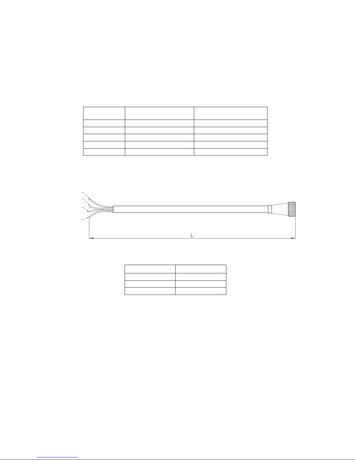
6.9. Command cable (4 poles)
This cable is without connector on motor’s controller side. Each wire is a command of a specific function
which is given to the motor’s controller with active high logic. When the command is active, signal of the
corresponding wire is high ( equal to Vcc); when the command is deactivated, signal is zero.
Each signal is determined short-circuiting the common wire via an internal relay.
Wire number Device on command
station Function
Yellow/Green Common 0 < Vcc < 60 V
Black
Relais
1
Lever is in Neutral position
Brown Relais 2 Lever is in Forward position
Grey Relais 3 Lever is in Reverse position
Maximum continuous current is 3 A for each wire.
Length Code
L= 3,0 m 3500.34-03000
L= 5,0 m 3500.34-05000
L= 7,0 m 3500.34-07000
Yellow/Green
Grey
Brown
Black

Flexball Italiana S.r.l. 12
8. Interface towards the motor controller and functioning principle
According to the position of the lever, the following commands are given through electrical
signals. Every position is clearly mechanical identified (with end of stroke or detent) and
electronic identified also:
Forward speed (switch 2)
Neutral (switch 1)
Backward (switch 3)
The following drawings are be used just as a reference to explain the lever working principle.
Electrical signals
•The analogue signal is ranging from 0,5 to 4,5 Volts and increase or decrease
proportionally with the movement of the lever. Position measurement is made with hall
effect sensor.
•Switch 1 is a normally open switch which is active when the lever is active (supply =
ON)and in neutral position.
•Switch 2 is a normally open switch which is active when the lever is in forward position.
•Switch 3 is a normally open switch which is active when the lever is in reverse position.
Forward
Reverse
0.5
V
4,5
V
Neutral
-43 degrees +43 degrees
Switch 3 = Reverse
Switch 1 = Neutral
Switch 2 = Forward

Flexball Italiana S.r.l. 13
8.1. Speed signal towards the motor’s controller
As standard, the electronic control lever provides 2 channel voltage output signals are reported in the
drawing here above. In case you need a different voltage profile, it must be specified when ordering.
As an alternative it is possible to interface to the motor’s controller via CANBus, in this case please refer to
the next chapter.
8.2. Programming of the delay when passing from Forward to Reverse or vice
versa
Sometimes to avoid shocks on the drive line, it is suggested to insert a delay time when inverting speed
direction. This delay does not occur when from neutral you move to forward or reverse.
Dip-switches 3 and 4 (see chapter 5) identify the delay time between forward reverse commands.
Dip
-
switch 3
Dip
-
switch 4
No delay during inversion of direction OFF OFF
Delay of 1 second during inversion of direction OFF ON
Delay of 2 seconds during inversion of direction ON OFF
Delay of 4 seconds during inversion of direction ON ON
8.3. CanBUS protocol
Every CANBus interface card has one output. Communication starts automatically at power-up.
This document refers to SAE J1939 CANBus protocol. The electronic system can handle also other
communication protocols.
Bit rate Repetition rate Identifier
29 bit in according to CAN 2.0B
default value default value description n°byte
250 Kbit/s 10 ms Priority 1
PGN 2
Address 1
Identifier:
Identifier Priority PGN Address
Hexadecimal values (_) 0x
_
_
0x
_
_
_
_
0x
_
_
Data field:
The 8 bytes of the Can Data Link are completely programmable according to the profile used by the motor
producer. In the data field you must write the motor speed reference. Necessary information for majority of
the motors are minimum speed and maximum speed without load.
8.4. Technical data of the CANBus interface card
Maximum speed which each channel can generate is 100 mA. Each channel output is protected against
short circuit towards ground and towards voltage supply. Termination resistor is already mounted on the
CANBus interface card but it can be removed when ordering at factory.

Flexball Italiana S.r.l. 14
21. Behaviour of the electronic system in case of failures
21.4. Troubleshooting
Irregularity What to check Section to refer
The lever doesn’t take the command
Check wiring and in case of
CANBus signalling, check that
the end of line resistance
termination on the motor
controller has been activated
Section 4.3.
21.5. LED diagnosis on command station
Command station produces signals to show either the operating conditions or possible causes of
irregularities.
LED indications
When it
happens Meaning/problem What to do
LED red is on Power up
Command station
is
powered, it has taken the
command and it is
configured correctly
-
LED green with fixed light
After power
up
Lever is in neutral, the
installation works correctly -
Green LED on command
station is blinking (50% ON,
50% OFF)
Might be a problem on the
positioning measuring
device of the command
station
Contact Flexball
Flexball Italiana S.r.l. 15
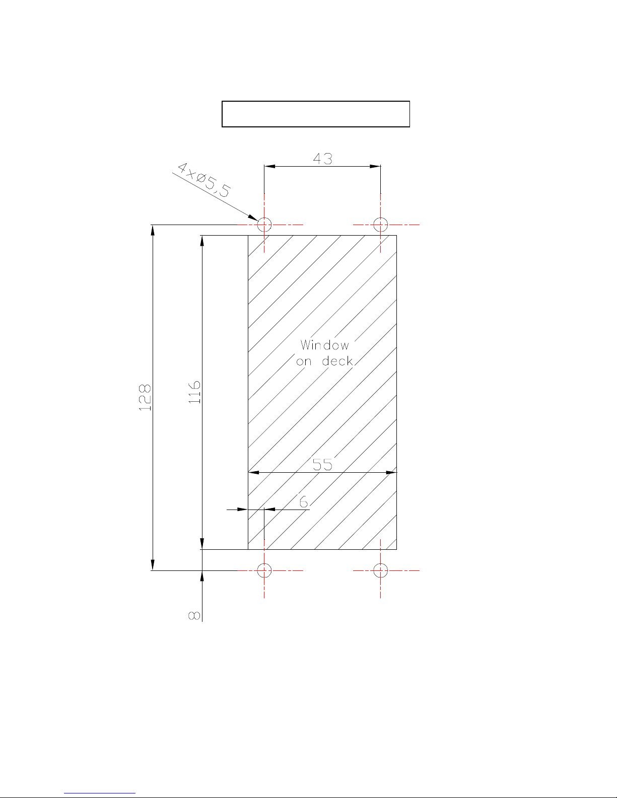
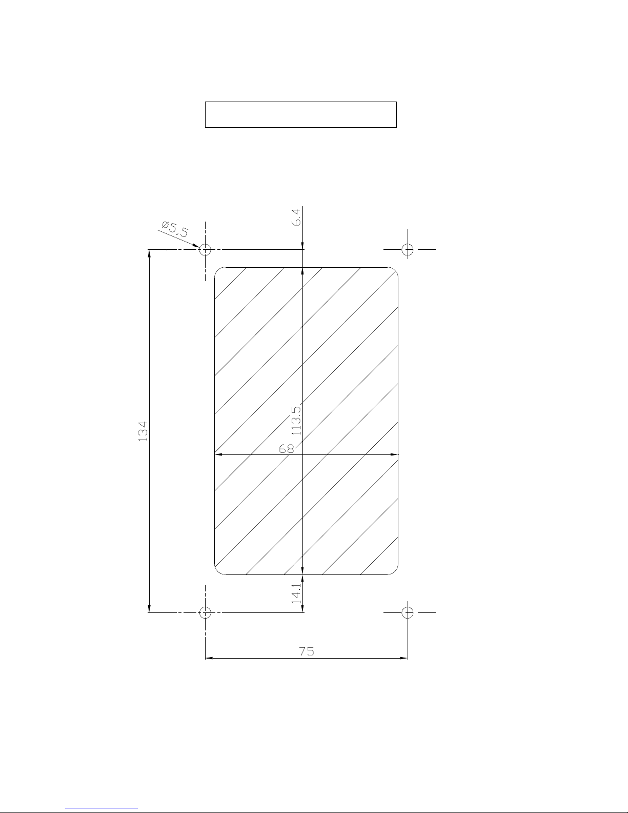
23. Drilling mask for command station
►Important: drilling mask is represented in scale 1:1
Command station series 4000
Front side
Flexball Italiana S.r.l. 16
►Important: drilling mask is represented in scale 1:1
Command station series 4500
Front side
This manual suits for next models
1
Table of contents


