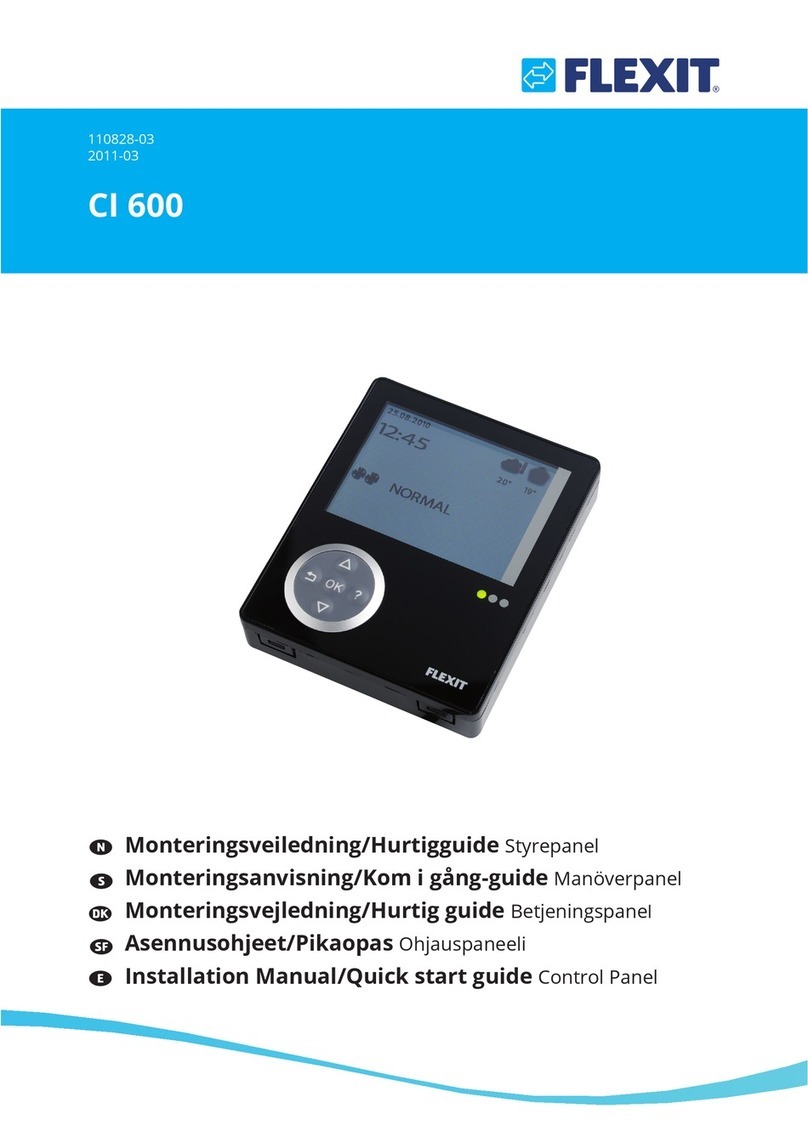
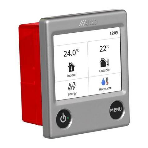
Flexit CI 70 User manual

ART.NR. 116402
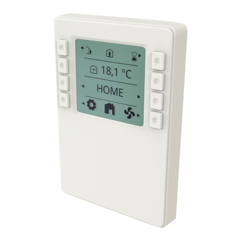
CI 70
ASSEMBLY AND USER INSTRUCTIONS
Control panel
116081EN-07
2023-02
Flexit
GO

2
CI 70
Our products are subject to continuous development and we therefore reserve the right to make changes.
We also disclaim liability for any printing errors that may occur.

3
Flexit GO
Contents
1. Scope .............................................................................................................................4
2. Mechanical design........................................................................................................4
2.1. Mounting.......................................................................................................................... 5
3. Icon description............................................................................................................8
3.1. Status icon description:................................................................................................9
4. Sleep page & home page description..................................................................... 10
4.1. Layer consept ...............................................................................................................11
5. Settings ...................................................................................................................... 11
5.1. General description ....................................................................................................11
5.2. Adjust time date & scheduler...................................................................................12
5.3. Fan speeds ....................................................................................................................13
5.3.1. Fan speed setting page ................................................................................14
5.4. Supply air temperatures ............................................................................................15
5.4.1. Home page – mode selection .....................................................................15
5.4.2. Home page – home/away selection ..........................................................16
5.4.3. Home page – in scheduler mode...............................................................16
5.4.4. Timer functions...............................................................................................17
5.5. Information....................................................................................................................17
5.6. Alarm...............................................................................................................................18
5.6.1. Alarm mode.....................................................................................................18
5.6.2. Filter alarm.......................................................................................................19
5HVHWȴOWHUWLPHU.............................................................................................19
5HVHWȴOWHUDODUP..........................................................................................19
5.6.5. Filter interval....................................................................................................19
5.6.6. Acknowledge and reset A-alarm ...............................................................20
5.6.7. Acknowledge B-alarm ..................................................................................20
5.6.8. Alarm codes.....................................................................................................21
5.6.9. Alarm codes – Hardware related errors...................................................21
5.6.10. Alarm codes – Application related errors ................................................21
5.6.11. Alarm codes – Communication errors......................................................21
5.7. Expert mode .................................................................................................................22
5.7.1. Read parameter mode .................................................................................22
5.7.2. Parameter list..................................................................................................23
6. Technical data............................................................................................................ 24
6.1. Mechanical dimensions..............................................................................................24
6SHFLȴFDWLRQ..................................................................................................................24
6.3. Maintenance .................................................................................................................26
6.4. Disposal..........................................................................................................................26

4
CI 70
1 Gasket for panel mounting
2 Base plate
• with screw holes for all common conduit oxes
• with gaining channels for wiring from center, up, or
bottom
3 Operator unit
1. Scope
• The CI 70 works together with all ventilation units in
the Nordic series
• The CI 70 operates control functions, such as fan and
temperature control
• The CI 70 communicates with 2-wire interface to the
controller through KNX PL-Link
2. Mechanical design
1 2 3
The subsections include important
information that is either decisive
for the sale or is essential for
engineering.
i
!
National safety regulations
Failure to comply with national
safety regulations may result in
personal injury and property
damage
• Observe national provisions and
comply with the appropriate safety
regulations.

5
Flexit GO
2.1. MOUNTING
m
c
0
2
ı
150 cm
• The devices are suitable for wall mounting and panel
mounting.
•5HFRPPHQGHG KHLJKW P DERYH WKH ȵRRU
• Do not mount the devices in recesses, shelves, behind
curtains or doors, or above or near heat sources.
• Avoid direct solar radiation and drafts.
• Seal the conduit box or the installation tube if any, as
DLU FXUUHQWV FDQ DHFW VHQVRU UHDGLQJV
• Adhere to designated ambient conditions.
The cable to the control panel is laid between the
ventilation unit and the control panel.
The control panel is designed for concealed installation
above the wallbox.
The included cable is 12 meters. If you need a longer
signal cable, order our 24 m cable. Art.no. 118258.
!
The cable to the CI 70 control panel
must be at least 30 cm from the
230 V cable (including dimmers,
thermostats, etc.). Power cables
must cross the CI 70 signal cable
at a right angle. For concealed
installation, the cable is laid in 16
mm cable tubes.
When you have installed the signal
cable, pull out all cable at the CI
70 panel to avoid surplus signal
cable at the ventilation unit. A roll
of cable at the unit may cause
disruption. Cut the signal cable to
the right length before the next
step.
CI 70 control panel must be
connected to the ventilation unit
before powered ON.
After power ON it takes approx.
3 min before the control panel
is in operation.
i

6
CI 70
1
2
3
A6V10733771M03
SEAL
Min. 3 mm screwdriver

7
Flexit GO
4
5
A6V10733771M05
h>20 mm
!
81.4
2- 52
111.4
2- 121.2
5
.
2
R
5
.
3
-
4
A6V10733771M09
[mm]
Connector Pin Description
+ KNX PL-Link (positive)
- KNX PL-Link (negative)
+ brown cord
- white cord
NOTICE! Installer can choose either pair of the pins to connect.
6
A6V10733771M07
Wires are NOT interchangeable!
The device is protected against faulty
wiring, but communications does
not work on interchanged wires.
i

8
CI 70
3. Icon description
AUTO MODE
HOME PAGE
AWAY MODE
HOME MODE
HIGH MODE
FIRE PLACE MODE
COOKER HOOD MODE
SUPPLY AIR
EXHAUST AIR
FAN SPEED SETTINGS
ROOM TEMPERATURE
GENERAL SETTINGS
CONFIRM
CANCEL
TIMER MODE
ELECTRICAL HEATER ENABLED
ELECTRICAL HEATER DISABLED
GO BACK
ALARM
ALARM – NOT ACKNOWLEDGED
ALARM – ACKNOWLEDGED
NORMAL - ACKNOWLEDGED
SERVICE REQUEST
SERVICE – NOT ACKNOWLEDGED
SERVICE – ACKNOWLEDEGED
READ PARAMETER MODE
CONFIRM ALARM
INDICATES AN OPERABLE ELEMENT
HOME
20°C
selection icons
info icons
mode descriptions
page description
Only as examplary picture. Not a spec reference.
selection icons
set point
page description
selection icons
status icons max 3 icons
at one time

9
Flexit GO
3.1. STATUS ICON DESCRIPTION:
Position 1
ALARM
ALARM – NOT ACKNOWLEDGED
ALARM – ACKNOWLEDGED
NORMAL - ACKNOWLEDGED BUT NOT RESETED
SERVICE REQUEST
SERVICE – NOT ACKNOWLEDGED
SERVICE – ACKNOWLEDEGED
AUTO MODE
Position 2
AWAY MODE
HOME MODE
Position 3
HIGH MODE
Status icons max 3 icons at one time
Icon position
123
HOME
20°C
Only as examplary picture. Not a spec reference.

10
CI 70
4. Sleep page & home page description
20.1°C
16:25
Sleep page
18.1°C
HOME
Home page
20.1°C
16:25
B-alarm
See section 5.6
Displays the room temperature at the panel. NB. If the panel is
LQVWDOOHGLQDFROGURRPWKHWHPSHUDWXUHPD\GLHUIURPWKH
indoor temperature elsewhere.
Display actual time.
%DFNOLJKWVZLWFKHVRDIWHUQRXVDJHLQPLQ
Display returns to sleep page after no usage in 4,0 min.
Display supply air temperature setpoint according to
operating mode.
Display actual W mode.
6HOHFWLRQRIGLHUHQWPRGHVSRVVLEOH
Select settings pages.
A-alarm
See section 5.6
Error code
(blinking
backlight)
(blinking
backlight)

11
Flexit GO
Special operation layer – medium prio
4.1. LAYER CONSEPT
Screens/views are prioritized according to use cases.
When screen with higher prio is called/activated it will be
the dominant one.
18.1°C
HOME
27 MIN
HIGH
ON
COOKER
1234
Basic layer – low prio
A-alarm layer – high prio
MAN
31.01.1900
5. Settings
5.1. GENERAL DESCRIPTION
Each page explained later in detail.
18.1°C
HOME
16:25
71%
67%
18.1°C
GeneralHome page Fan speed Supply air

12
CI 70
5.2. ADJUST TIME DATE & SCHEDULER
Adjust time:
Press the arrows beside the clock: <- to reduce and -> to
increase the time. Hold down to move faster.
Adjust the date:
Press the arrows beside the date: <- to reduce and -> to
increase the date and year. Hold down to move faster.
Adjusting MAN/AUTO:
Via the FlexitGO app, you can set the unit to operate
in calendar mode, i.e. it changes speed according to a
preset timetable. You can select whether the unit will
operate in calendar mode via the panel. This is done by
selecting HOME mode and then going to General mode
(see 5.1). Use the arrows to switch between:
0$1 &DOHQGDU R
$872 &DOHQGDU DFWLYH LI LW LV FRQȴJXUHG LQ WKH DSS
18.1°C
HOME
MAN
31.01.1900
16:25
Home page General
MAN
01.01.2000
16:25
Adjust time and date
MAN
01.01.2000
16:25
AUTO
01.01.2000
16:25

13
Flexit GO
71%
67%
Fan speed
5.3. FAN SPEEDS
mode selection
supply fan adjustment
exhaust fan adjustment
18.1°C
HOME
Home page
NB. The fan speeds are factory-set
to: Away 50%, Home 75% and High
100%.
High must always be set higher
than Home, which must be set
higher than Away.
For example, if you want to set
Home lower than 50%, you must
first reduce Away so it is always
lower than Home. The same
applies between Home and High.
i
Home: This is a constant mode and is Intended for normal use when the
building is occupied.
Away: This is a constant mode and is intended for use when the building is
unoccupied for longer periods. You can also set a delayed start, which can be
useful if you just got out of the shower before you leave the house.
High: This can be both a constant mode and a temporary mode with a set
duration. It is intended for use when a higher ventilation demand is temporarily
required.
Fireplace: This is only available as a temporary mode with a set duration.
ΔW LV LQWHQGHG IRU WHPSRUDU\ XVH WRJHWKHU ZLWK D ȴUHSODFH ΔW FUHDWHV DQ
overpressure in the building to facilitate smoke to go up the chimney, which
prevents smoke to enter the building.
Cooker hood: This mode can only be activated using a wireless or cabled
accessory, which is mounted in your cooker hood. It activates when you use
your cooker hood.

14
CI 70
5.3.1. Fan speed setting page
Press of button 5 will change the views in loop towards
right.
Press of button 1 will change the views in reverse order
- loop towards left.
71%
67%
92%
89%
92%
38%
52%
49%
92%
38%
71%
67%
92%
89%
92%
38%
52%
49%
92%
38%

15
Flexit GO
5.4. SUPPLY AIR TEMPERATURES
18.1°C
Supply air
mode selection
supply air temperature adjustment
electrical heater ENABLE/DISABLE /
18.1°C 16.1°C
30 min
Supply air
Home
Supply air
Away
HOME/AWAY adjustments
Time delay setting when switching to
AWAY mode with button 1.
5.4.1. Home page – mode selection
18.1°C
HOME
18.1°C
HOME
Home speed mode High speed mode
18.1°C
HIGH

16
CI 70
5.4.2. Home page – home/away selection
18.1°C
HOME
16.1°C
AWAY
Away mode Home mode
18.1°C
HOME
5.4.3. Home page – in scheduler mode
18.1°C
HOME
scheduler mode (time program)
18.1°C
HOME
18.1°C
HIGH
16.1°C
AWAY
Home speed mode High speed mode Away mode

17
Flexit GO
5.4.4. Timer functions
18.1°C
HOME
30 min
HIGH
30 min
FIRE
Home page High Fire place
27 min
HIGH
If activated
returns to HOME PAGE after
prolongation time is elapsed
returns to HOME PAGE
if function is canceled
5.5. INFORMATION
Activation of cooker hood function via Digital input or
wireless accesorie.
18.1°C
HOME
Home page
ON
COOK
Cook
2QRYLDSK\VLFDO
”Digital input” constant signal

18
CI 70
18.1°C
HOME
keep both buttons pressed
until new page is entered
Home page
----
P
----
P
No active alarms No active service
5.6. ALARM
In case of alarm, the display will start to blink, and the
appearance of the information will depend on alarm
class, according to the pictures below.
A-alarm
Error code
(blinking
backlight)
(blinking
backlight)
20.1°C
16:25
B-alarm
5.6.1. Alarm mode

19
Flexit GO
5.6.2. Filter alarm
:KHQ D ȴOWHU DODUP LV DFWLYH D WRRO NH\ LV GLVSOD\HG
DQG WKH DODUP FRGH LV GLVSOD\HG $IWHU WKH ȴOWHUV
in the unit have been replaced, follow the procedure,
GHVFULEHG LQ WZR VWHSV EHORZ WR UHVHW WKH ȴOWHU WLPHU
(section 5.6.3) and the alarm. (section 5.6.4)
5.6.3. 5HVHWȴOWHUWLPHU
7KLV IXQFWLRQ LV XVHG WR UHVHW WKH ȴOWHU WLPHU
7KH IXQFWLRQ FDQ EH XVHG WR UHVHW WKH ȴOWHU WLPHU EHIRUH
UHVHWLQJ WKH ȴOWHU DODUP RU LW FDQ DOVR EH XVHG WR UHVHW
WKH ȴOWHU WLPHU LI WKH ȴOWHU LV UHSODFHG EHIRUH WKH ȴOWHU
alarm has appeared.
NB! In case you can’t locate parameter P41 on your
product, this functionality is not available. Please go
WR WKH QH[W VWHS VHFWLRQ LQ RUGHU WR ȴQDOL]H WKH
procedure.
5.6.4. 5HVHWȴOWHUDODUP
7KLV IXQFWLRQ LV XVHG WR UHVHW WKH ȴOWHU DODUP
5.6.5. Filter interval
7KH XQLW KDV D GHIDXOW VHWWLQJ IRU WKH ȴOWHU DODUP LQWHUYDO
of 6 months. If you want to adjust this, you need to
connect to the unit via the FlexitGO app.
Hold down both buttons
until the next page is
shown.
Then press the right button
to select the active alarm.
&RQȴUPUHVHW E\ SUHVVLQJ
the button.
When the alarm has been
FRQȴUPHG WKH SDQHO
automatically returns to the
start page.
1020
HOME
P
---- 1020
P
20.0°C
HOME
Ready
P
20.0°C
HOME
P41
Reset
P
P41
Ready
P
P41
1020
HOME
P
----

20
CI 70
5.6.6. Acknowledge and reset A-alarm
In case of critical A-alarms, application operation is
locked until alarm is acknowledged and reset.
----
P
18.1°C
HOME
1234
1234
P
18.1°C
HOME
18.1°C
HOME
Acknowledge alarm
No alarms
Active alarms
Keep both buttons pressed
until new page is entered
Action needed - correct
disturbance
Keep both buttons pressed
until new page is entered
1234
P
Reset alarm
5.6.7. Acknowledge B-alarm
Application is still operational (as much as possible),
alarm has to be acknowledged.
18.1°C
HOME
18.1°C
HOME
Acknowledge service
QRWLȴFDWLRQ
No alarms
Press button to enter
acknowledge page
Action needed - correct
disturbance
1234
HOME
$FWLYH VHUYLFH QRWLȴFDWLRQ
Keep both buttons pressed
until new page is entered
1234
P
Other manuals for CI 70
1
Table of contents
Other Flexit Control Panel manuals
Popular Control Panel manuals by other brands
Siemens
Siemens MICROMASTER 4 Getting started guide
Dea
Dea NET230N operating instructions

SJE Rhombus
SJE Rhombus 115 Installation Instructions and Operation
Balboa Water Group
Balboa Water Group BP2 Series User Interface and Programming Reference
tau
tau K580M installation guide
Nakanishi
Nakanishi E4000-PB Operation manual
Radionics
Radionics D10024A user manual
tau
tau K898M installation guide
PS Engineering
PS Engineering PMA8000BT System installation and operation manual
Hornby
Hornby 'Select' Unit Operator's manual

Global Fire Equipment
Global Fire Equipment JUNIOR MINI-REP installation manual
Victron energy
Victron energy Color Control GX manual
