tau K580M User manual

1
K580M
GUIDA ALL’INSTALLAZIONE
INSTALLATION GUIDE
INSTALLATIONSANLEITUNG
NOTICE D’INSTALLATION
GUÍA PARA LA INSTALACIÓN
GUIA DE INSTALAÇÃO
K580M
Quadro di comando per motoriuttore T-ONE5, T-ONE8, T-ONEXL e MASTER20QR/QM
Control panel for T-ONE5, T-ONE8, T-ONEXL and MASTER20QR/QM gearmotor
Steuerplatine für den getriebemotor T-ONE5, T-ONE8, T-ONEXL und MASTER20QR/QM
Logique de commande pour motoréducteur T-ONE5, T-ONE8, T-ONEXL et MASTER20QR/QM
Panel de mandos para motorreductor T-ONE5 , T-ONE8, T-ONEXL y MASTER20QR/QM
Quadro de comando para motorredutor T-ONE 5, T-ONE8, T-ONEXL e MASTER20QR/QM
Via Enrico Fermi, 43 - 36066 Sandrigo (VI) Italia
Tel +39 0444 750190 - Fax +39 0444 750376
info@tauitalia.com - www.tauitalia.com
IT - Istruzioni originali
D-MNL0K580M 17-11-2015 - Rev.10
2
K580M
SCHEMA CABLAGGIO K580M / K580M WIRING DIAGRAM / SCHALTPLAN DER K580M
FR
SENS
TCA
M-OP
CLS
OLS
COM
GND
+5V
ENC
FS2
FS1
M-COM
M-CL
P1
P2
F1
3,15A
F2
500mA
DL1
DL2
DL3
DL4
DL5
DL6
DL7
DL8
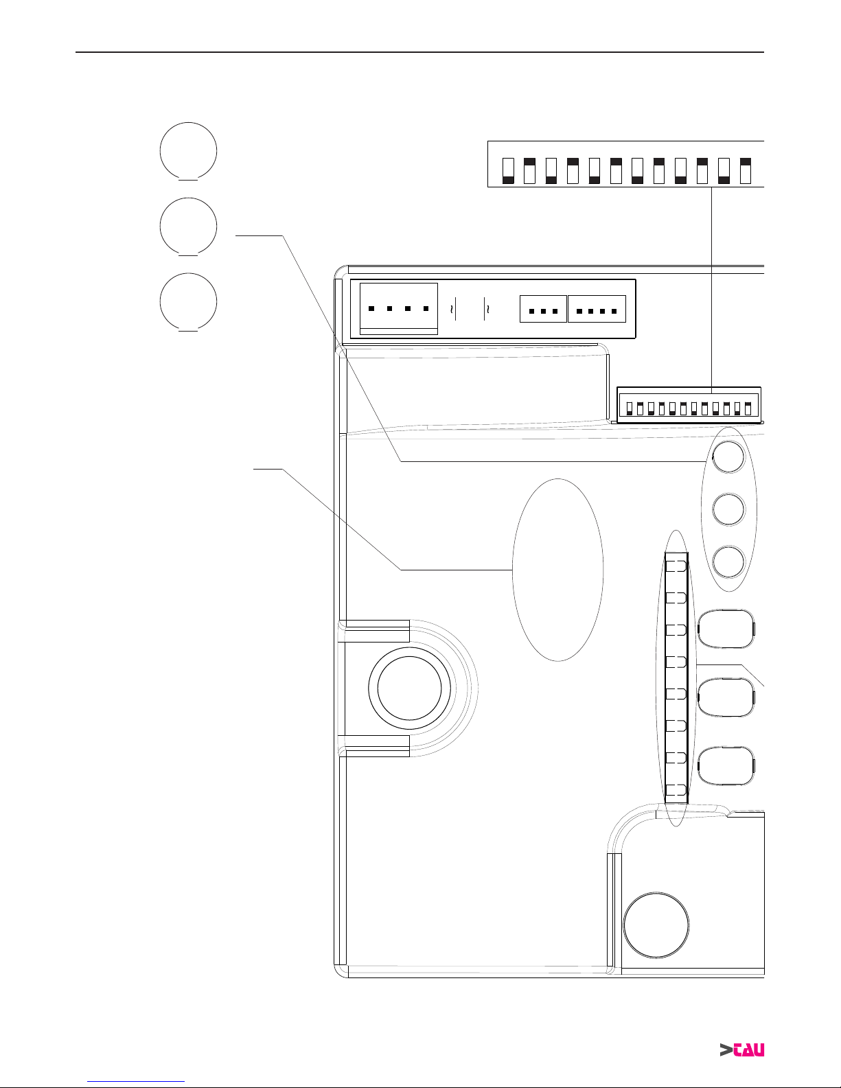
1 2 3 4 5 6 7 8 9 10 11 12
1 2 3 4 5 6 7 8 9 10 11 12
K580M
Dip-switchesON
M1M2
M3
TCA
+-
SENS
+-
FR
+-
3
K580M
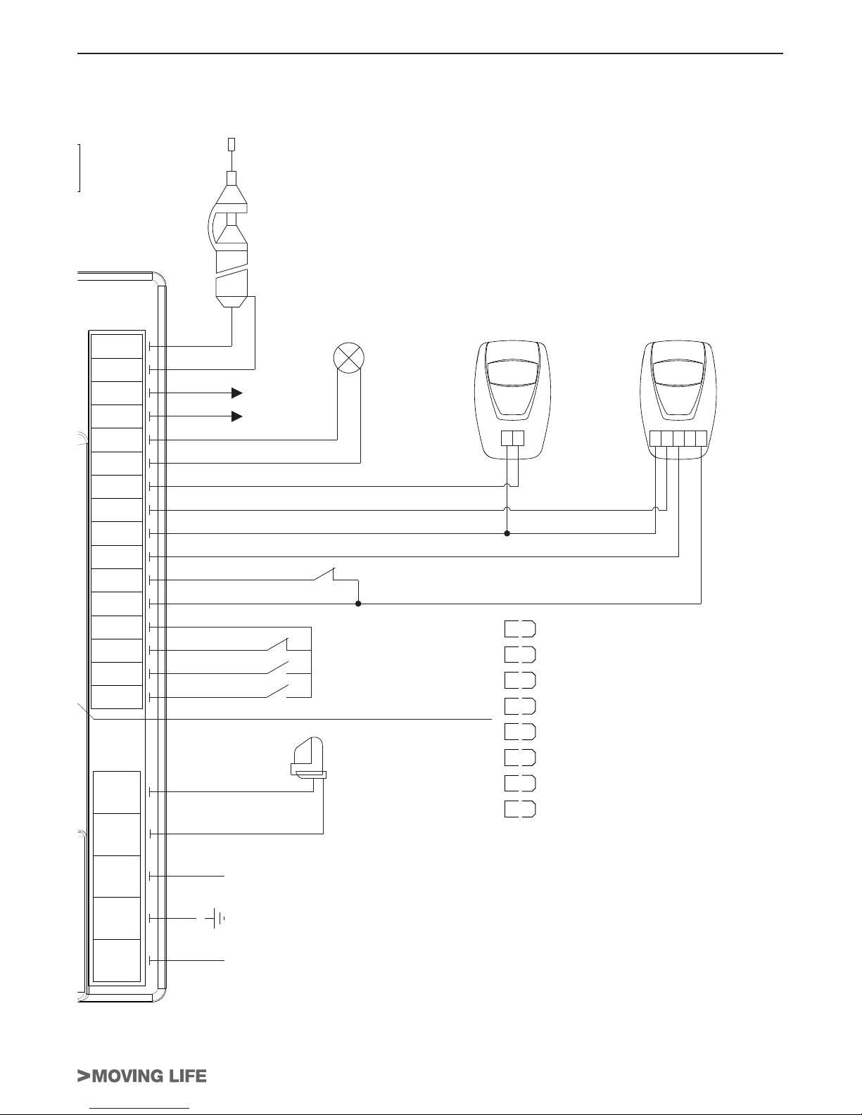
SCHÉMA CÂBLAGE K580M / ESQUEMA DEL CABLEADO K580M / ESQUEMA ELÉCTRICO K580M
6
7
8
9
10
11
12
13
14
15
16
17
18
19
20
21
1
2
3
Neutral
230 Vac
Power supply
Phase
4
5
P1
P2
12
12
Flashing
light
230 Vac
max. 50W
Open/Close
Pedestrian
Stop
Common
Gate open
warning light
max. 3W
2nd radio
channel
Antenna
DL1
DL2
DL3
DL4
DL5
DL6
DL7
DL8
PHOTO
SENSITIVE EDGE
CLOSE LIMIT SWITCH
OPEN LIMIT SWITCH
STOP
PEDESTRIAN
OPEN/CLOSE
RADIO CONTROLS
Photocells
Common
Photocell (N.C.)
Photocell TX
Fixed safety edge
RX
1 2 3 4 5
TX
1 2
0 Vac
Photocell RX - 24 Vac

12
K580M
MANUFACTURER’S DECLARATION OF INCORPORATION
(in accordance with European Directive 2006/42/EC App. II.B)
Manufacturer: TAU S.r.l.
Address: Via E. Fermi, 43
36066 Sandrigo (Vi)
ITALY
Declares under its sole responsibility, that the product: Electronic control unit
designed for automatic movement of: Sliding Gates
for use in a: Residential / Communities
complete with: Radioreceiver
Model: K580M
Type: K580M
Serial number: see silver label
Control panel for T-ONE5, T-ONE8, T-ONEXL and
MASTER20QR/QM gearmotor
sliding gate) of for assembly with other devices used
Also declares
- 2006/95/EC Low Voltage Directive
- 2004/108/EC Electromagnetic Compatibility Directive
and, where required, with the Directive:
- 1999/5/CE Radio equipment and telecommunications terminal equipment
Also declares that it is not permitted to start up the machine until the machine in which it is incorporated or of
pertinent to the quasi-machinery.
Legal Representative
_________________________________________
Loris Virgilio Danieli
Name and address of person authorised to draw up all pertinent technical documentation:
Loris Virgilio Danieli - via E. Fermi, 43 - 36066 Sandrigo (Vi) Italy
ENGLISH

13
K580M
WARNINGS
manual can be considered as being of interest to end users. This manual is enclosed with control unit
Important information:
Disconnect the panel from the power supply before opening it.
Any other use is considered improper and is consequently forbidden by current laws.
This directive includes the following prescriptions:
laws, regulations and directives.
When designing its products, TAU observes all applicable standards (please see the attached decla-
ration of conformity) but it is of paramount importance that installers strictly observe the same stand-
ards when installing the system.
and doors” category may not install systems under any circumstances.
Whoever ignores such standards shall be held responsible for any damage caused by the
system!
Do not install the unit before you have read all the instructions.
INSTALLATION
Before proceeding, make sure the mechanical components work correctly. Also check that the
gear motor assembly has been installed according to the instructions. Then make sure that
the power consumption of the gear motor is not greater than 3A (otherwise the control panel
may not work properly).
-
Note: it is compulsory to earth the system and to observe the safety regulations that are in
force in each country.
-
ENGLISH

14
K580M
CONTROL PANEL FOR ONE 230V AC MOTOR
ATTENTION:
- do not use single cables (with one single wire), ex. telephone cables, in order to avoid
breakdowns of the line and false contacts;
- do not re-use old pre-existing cables.
TESTING
When you have completed the connection:
off only when the controls to which they are associated are operated.
be illuminated steadily.
TECHNICAL CHARACTERISTICS
Power input to board
Nominal power 400 W
Input voltage of motor circuits
IP 44
TERMINAL BOARD CONNECTIONS
Terminals Function Description
1 - 2 - 3 POWER
SUPPLY
4 - 5 FLASHING
LIGHT
6 - 9 OPEN/CLOSE
7 - 9 PEDESTRIAN
N.B. by factory setting the automation will open 120 cm.
8 - 9 STOP
10 - 11 SENSITIVE
EDGE
NOTE: if a resistive sensitive edge is connected, set dip-
switch no. 12 to ON;
switch no. 12 to OFF;
ENGLISH

15
K580M
10 - 12 PHOTOCELLS
opening in order to allow the obstacle to be removed (if dip switch
IN SERIES.
Note: the photocell transmitter must always be supplied by
terminals no. 13 - 15, since the safety system test (photo-
test) is carried out on it. To override the testing of the safety
system, or when the photocells are not used, set dip-switch
no. 6 to OFF. If the photo-test is not successful, the control
unit will not operate.
13 - 14 RX
PHOTOCELLS
13 - 15 TX
PHOTOCELL
16 - 17 GATE OPEN
LED
18 - 19 2nd RADIO
CHANNEL
Warning: to connect other devices to the 2nd Radio Channel
(area lighting, pumps, etc.), use an additional auxiliary relay.
20 - 21 AERIAL
M1 LIMIT
SWITCH
(CLS),
(OLS)(COM)
M2 ENCODER (GND),
(+5V)(ENC)
FS1 - FS2 CAPACITOR
M3 230V AC
MOTOR
(M-COM) (M-CL)
(M-OP).
LOGIC ADJUSTMENTS
TRIMMER
FR.
Turning the
trimmer clockwise (+) increases the motor torque, turning it anticlockwise (-) re-
duces it.
SENS Adjustable only with ENCODER enabled (DIP 11 ON).
Note: by rotating the TRIMMER FR. clockwise the sensitivity to obstacles of the
operaor decreases vice-versa, by rotating it
anti-clockwise, the sensitivity to obstacles of the operator increases and therefore
the thrust force decreases.
WARNING: with the trimmer at maximum, the obstacle detection is disabled!!
T.C.A.
Dip switch
1AUTOMATIC
CLOSING
On after opening, the gate automatically closes when the delay set on the
Off automatic closing disabled.
ENGLISH

16
K580M
22 / 4 STROKE
On
switch 4).
Off in the same conditions, the same command sequence causes the
3
OPENING
PHOTOCELLS
OPERATION
On during opening, cutting photocell stops the gate until the obstacle is
Off during opening, the photocell does not cut in.
4NO
REVERSE
On
Off the open-close pushbutton reverses the direction of movement of the
gate even while it is opening.
5PRE-
FLASHING
On
Off
6PHOTOCELL
TEST
On
Off
Note: to be used when the photocells are not used.
7 - 8
Dip 7 Dip 8 Function
Off Off
Gate contact open: The contact activates on opening the gate and remains
once the gate has completed its closure movement.
Off On Bistable function active: the radio control impulse causes the contact to activate
and remain active until the subsequent impulse.
On Off Monostable function active for 2 sec.: the radio control impulse causes the
On On Monostable function active for 180 sec.: the radio control impulse causes the
9GATE
TYPE
On setting for heavy gates
Off setting for standard gates
10
OPENING
DIRECTION
SETUP
On
Off
11
ENCODER On
Off
NOTE: moving DIP 11 from ON to OFF (or vice versa), learning process has to be
initialized again.
12 SENSITIVE
EDGE
On
Off
If the obstacle detection function (which can be set through trimmers FR and SENS) gets activated
-
noeuvre, the gate opens fully.
WARNING: the control panel logics may interpret mechanical friction as an obstacle.
ENGLISH

17
K580M
SETUP PROCEDURE
WARNING: The learning process has to be done even if ENCODER function is disabled
(DIP 11 OFF).
It is recommended to start the learning process with the gate partially opened.
-
cally the learning process:
If the automation opens instead of closing, stop the learning process (by cutting the
photocells or opening the STOP contact), invert DIP 10 and continue the learning pro-
WARNING: - SETTING SLOWDOWN: (skip this procedure to disable slowdown) During
the opening cycle press P1 or close the OPEN/CLOSE contact at the desired position
where to start the slowdown.
WARNING: - SETTING SLOWDOWN: (skip this procedure to disable slowdown) During
the opening cycle press P1 or close the OPEN/CLOSE contact at the desired position
where to start the slowdown.
WARNING: if during the learning process either the STOP, or PHOTOCELLS or SAFE-
TY EDGE contact will be opened the automation stops. By pressing P1 or closing the
OPEN/CLOSE contact the learning process starts again from pont nr. 1
ADVANCED FUNCTIONS
Clock function:
open at certain times during the day, after which it reverts to automatic closing.
Note: the gate remains open as long as the Op/Cl input continues to be activated.
“Open only” function: -
ing command and the gate will close only after the automatic closure time has elapsed.
“Gate contact open” function:
will act as a dry contact which indicates when the gate is open. This function can be used to connect
DIAGNOSTICS LED
DL1 (PHOTO)
DL2 (SENSITIVE EDGE)
DL3 (CLOSE LIMIT SWITCH)
DL4 (OPEN LIMIT SWITCH)
DL5 (STOP) STOP button green LED signal
DL6 (PEDESTRIAN) PEDESTRIAN button red LED signal
DL7 (OPEN/CLOSE)
DL8 (RADIO CONTROLS)
LED - DL8
always on: normal operation;
photo-test error;
Disable photo-test (dip-switch 6 OFF), check the operation of the photocells and
their connection;
no encoder signal (only with dip 11 ON);
Check wiring, check encoder by TEST-ENCODER (optional);
ENGLISH

18
K580M
6 obstacle detected (only with dip 11 ON);
Make sure there are no obstacles across the path of the gate and that it slides
smoothly;
Learning process not completed;
Repeat the Learning process procedure;
Learning procedure in progress;
(duration 30 sec.)
Only when powered up: wrong power supply frequency (50 Hz default set-
ting);
RESTORING AUTOMATIC OPERATION
Should the gate needs to be operated manually, use the release system. After a manual operation:
433.92 MHz BUILT-IN RADIO RECEIVER
4RP) which can be set on both the two channels as desired.
-
-
for about 3 seconds without performing any memorisation.
procedure of remote programming of the new transmitters. Follow the procedure written on the in-
ENGLISH

19
K580M
MALFUNCTIONS: POSSIBLE CAUSES AND SOLUTION
The automation does not start
The radio control has very little range
The gate opens the wrong way
GUARANTEE: GENERAL CONDITIONS
sales document, receipt or invoice).
-
manship or materials.
The guarantee does not cover the following cases:
improper repairs, incorrect installation, or other reasons that do not depend on TAU.
-
ENGLISH
Other manuals for K580M
2
Table of contents
Other tau Control Panel manuals


Popular Control Panel manuals by other brands

Pulsar
Pulsar 17/TRP40/DSPR/S Assembly instruction

Digital Monitoring Products
Digital Monitoring Products XTL Series user guide

INIM
INIM GameOver SmartLiving 505 Installation and programming manual

Texecom
Texecom Premier 8168 Programming steps

Balboa
Balboa ML900 user guide

MGC
MGC RAXN-4000LCD Installation and wiring manual


