Flexit ProTouch 118257 User manual

ART.NO. 118257
2020-11
ProTouch
118276EN-01
USER MANUAL
Control panel

2
PROTOUCH

3
PROTOUCH
Contents
1. Starting ProTouch ........................................................................................................4
2. About .............................................................................................................................6
3. Overview........................................................................................................................7
3.1. Start page ...........................................................................................................7
3.2. Main menu .........................................................................................................8
3.3. Flow diagram......................................................................................................9
4. Service switch ............................................................................................................ 10
5. Alarm .......................................................................................................................... 11
6. Settings....................................................................................................................... 11
7. Trends......................................................................................................................... 12
8. Connection................................................................................................................. 13
9. Timetable ...................................................................................................................13

4
PROTOUCH
1. Starting ProTouch
1. Connect the spiral cable to the contact marked
RS485 at the back of the panel. Connect the other
end of the cable to the RJ45 contact on the side of
the switchgear cabinet on the unit.
2. The panel starts automatically and the overview
page appears.
To change the language, press the menu button at the
top left of the panel.
3. Log in with your password
In order to make changes, it is normally necessary to
log in. There are four authority levels, and three of them
are password protected. The menus under Operation
control show more options or fewer, depending on
the level at which you are logged in. The following key
symbols are used in the main manual for the automatic
control system to describe login levels required to allow
GLHUHQWPHQXVIXQFWLRQVWREHYLVLEOHDQGHGLWDEOH
It refers to:
Level 1 (GUEST ACCESS): No restrictions, no password
required.
Read access to all menus except system parameters,
FRQȴJXUDWLRQDQGGHWDLOPHQXV
Read access to alarm lists and alarm history.
Level 2: End user, password 1000. One-key symbol
1
1
3
12

5
PROTOUCH
4
5
All rights as for level 1, plus:
ȏ5HDGDFFHVVWRDOOPHQXVH[FHSWFRQȴJXUDWLRQPHQXV
• Write access to the most important setpoints
6HWSRLQWV6HWWLQJV!6HWSRLQWV
• Alarms and alarm history can be acknowledged and
reset.
Level 3: System administrator, password 2000.
Two-key symbol
All rights as for level 2, plus:
5LJKWVWRDOOPHQXVH[FHSWΔ2FRQȴJXUDWLRQDQGV\VWHP
settings.
Level 4: OEM, password given only in consultation with
the Flexit service organisation.
Three-key symbol
All rights as for level 3, plus:
Rights to all menus and system settings.
4. Next, press Preferences, and then Select language.
Choose between English-United States and press
APPLY to activate your choice.
Press the menu icon at the top left to go back to the
overview.
7RDGMXVWVHWWLQJVDQGFRQȴJXUHWKHXQLWSUHVV
Operation control. A menu tree will be shown like
the one in ProPanel and on the WEB connection.
See the main manual for CS2500 for more information
about which functions are available.

6
PROTOUCH
2. About
8QGHUWKH$ERXWPHQX\RXZLOOȴQGWKH(8/$(1'86(5
LICENSE AGREEMENT). Read this before starting to use
the panel.
7
PROTOUCH
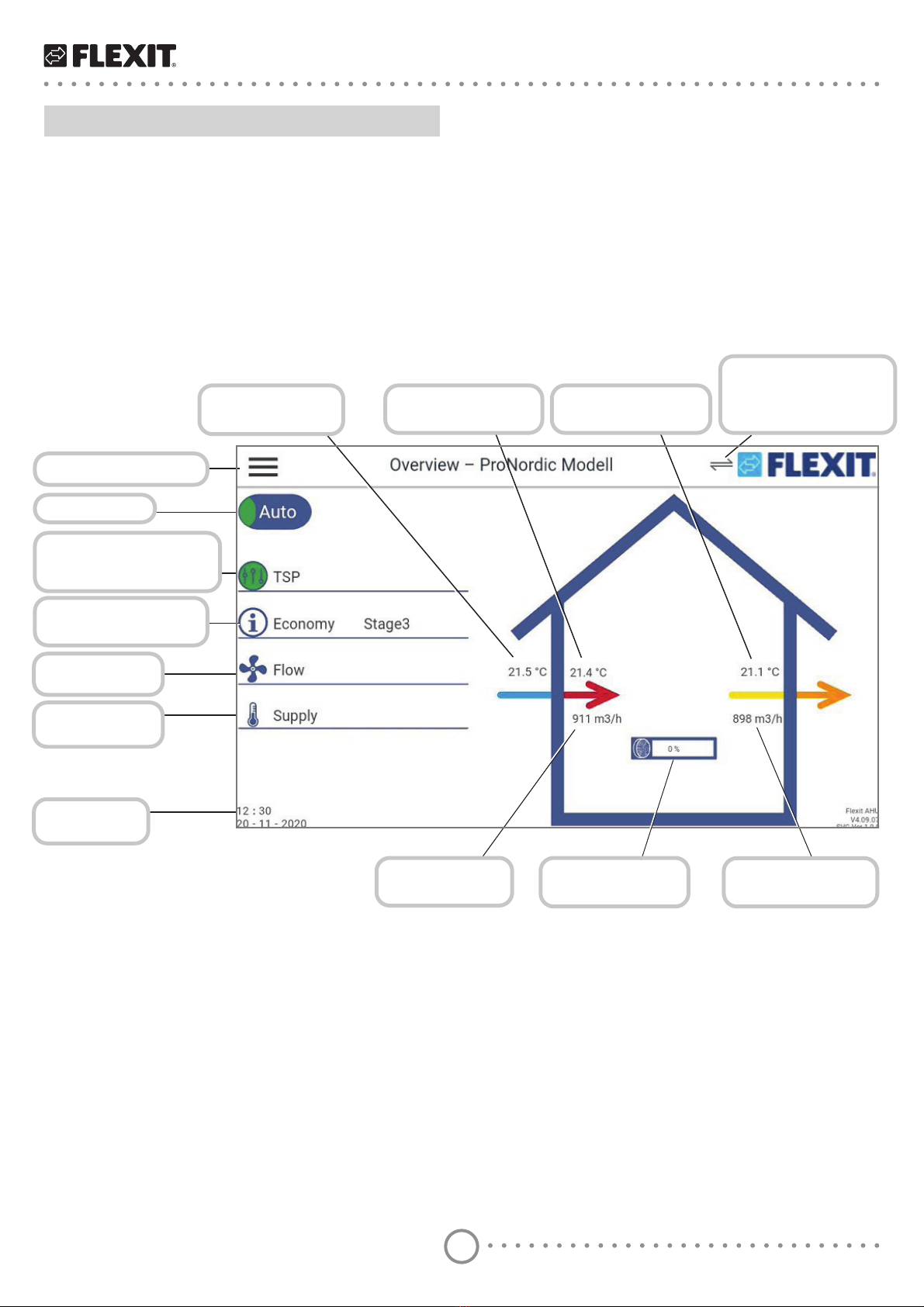
Go to the main menu
Service switch
Info LED and display
of current operating
mode
Current temperature
mode and fan step
Current temp
regulation type
Current time
and date
Current fan
regulation type
Current outdoor
temperature
Current supply air
temperature
Current extract air
temperature
Shows that the panel
is communicating
with the unit
&XUUHQWDLUȵRZ
supply air
&XUUHQWDLUȵRZ
extract air
Current heat
exchanger force
3. Overview
The Overview is the starting page on the panel, where
you can see a simple overview of the most important
parameters. The appearance of the overview image
YDULHVGHSHQGLQJRQWKHFRQȴJXUDWLRQRIWKHXQLW
E.g. if heating and cooling coils or other accessories are
activated, they will be shown in the overview.
3.1. Start page

8
PROTOUCH
Menu for trends
Overview diagram
Time setting
calendar
Connections to
the panel
Panel settings
Information
about the panel
and software
Alarm handling
Login menu
Flow diagram
6HWWLQJVDQGFRQȴJXUDWLRQ
of the unit
Shows that the panel is
communicating with the unit
3.2. Main menu
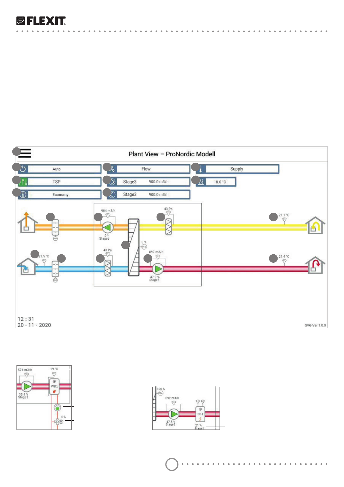
9
PROTOUCH
1. Link to main menu
2. Status of service cut-out-switch
3. ΔQIR/('DQGGLVSOD\RIFXUUHQWRSHUDWLQJPRGH
4. Temperature mode
5. Fan regulation type
6. 6XSSO\DLUIDQVWDJHDQGDLUȵRZ
7. ([WUDFWDLUIDQVWDJHDQGDLUȵRZ
8. Temperature regulation
9. Heating set point
10. Exhaust air damper
11. ([WUDFWDLUIDQDLUȵRZIRUFHDQGIDQVWDJH
12. ([WUDFWDLUȴOWHUSUHVVXUHGURS
13. Extract air temperature
14. Rotating heat exchanger and force
15. Outdoor temperature
16. Outdoor air damper
17. 2XWGRRUȴOWHUSUHVVXUHGURS
18. 6XSSO\DLUIDQDLUȵRZIRUFHDQGIDQVWDJH
19. Supply air temperature
7KHDSSHDUDQFHRIWKHȵRZGLDJUDPYDULHVGHSHQGLQJRQWKHFRQȴJXUDWLRQRIWKHXQLW(JLIKHDWLQJDQGFRROLQJFRLOV
RURWKHUDFFHVVRULHVDUHDFWLYDWHGWKH\ZLOOEHVKRZQLQWKHȵRZGLDJUDPΔWLVHDV\WR]RRPLQE\VSUHDGLQJWZRȴQJHUV
apart on the screen.
:KHQDFRLOLVFRQȴJXUHGLQWKHV\PEROIRUWKHFRLOZLOODSSHDU
1
2
3
4
5
6
7
8
9
10 11 12 13
14
15 16 17 18 19
3.3. Flow diagram
All values are in the current mode.
Water heating element Electric heating coil
return water sensor, temperature
FLUFXODWLRQSXPSRQR
valve motor, force
Electric heating coil, force
10
PROTOUCH
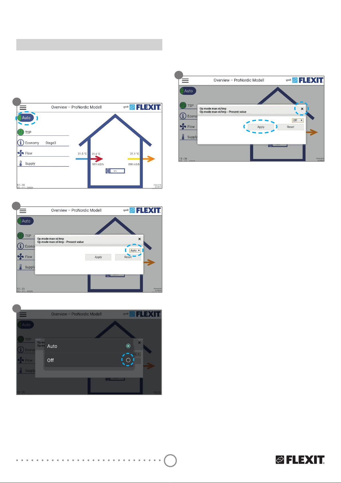
4. Service switch
The service switch is used to stop the unit for servicing.
NB. If an electric heating coil is installed and active, there
will be 180 seconds run-on time to cool down the coil
before the unit stops.
1. Press on the “Stop” switch at the top left
2. Press on Auto in the pull-down menu.
3. Select OFF in the pop-up box.
1
2
3
3UHVV$SSO\WRFRQȴUP7KHQFORVHWKHER[E\
pressing X.
4
Table of contents
Other Flexit Control Panel manuals


