Riello CBD 20 PLUS User manual

HELIOTERM INVERTER
Doc-0074814 Rev. 0
1
IT
Avvertenze preliminari
Montaggio
Montaggio e connessioni pannello di
comando a bordo macchina
Questa istruzione è parte integrante del libretto
dell’apparecchio sul quale viene installato il KIT. A tale
libretto si rimanda per le AVVERTENZE GENERALI e per le
REGOLE FONDAMENTALI DI SICUREZZA.
Infilare il pannello di controllo nella sua sede nella parte
superiore dell’apparecchio e fissarlo con le due viti a corredo
(rif. A).
Per installare la scatola dei collegamenti:
aprire la scatola (rif. B);
incastrare il dente inferiore nell’apposita feritoia (rif. C) sul
fianco dell’apparecchio;
agganciare la parte superiore della scatola al fianco (rif. D);
fissarla con le due viti a corredo (rif. E);
fissare il cavo di terra alla struttura dell’apparecchio
utilizzando la vite a corredo (la forza minima che deve
essere esercitata per l’avvitamento deve essere di circa 2N);
collegare il connettore rapido del motore (FAN_COIL ) a
quello presente sulla scheda (rif. I) *;
nei 2 terminali del morsetto LOCK (rif. L) è presente un ponte
che garantisce il funzionamento delle versioni Design
Inverter e Design Inverter Plus prive di microinterruttore.
Il comando a bordo macchina con selettore di velocità e
ON/ OFF a pulsante, termostato ambiente regolabile da
5 a 40°C, selettore estate inverno e funzione di minima
temperatura invernale (30°C) e massima temperatura
estiva (20°C) è adatto per l’installazione a bordo macchina
e dispone di una uscita a 230 V per il controllo di
un’elettrovalvola.
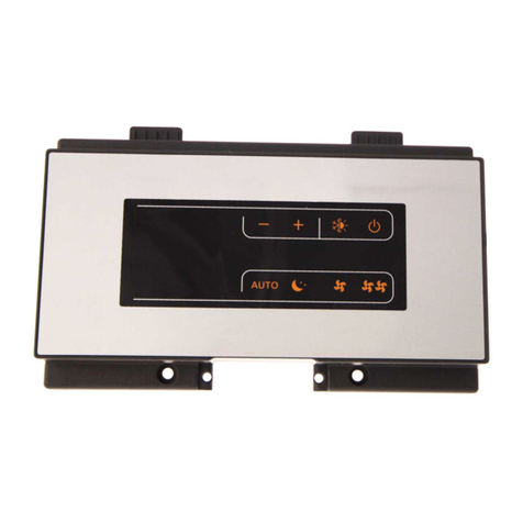
CBD 20 PLUS - PANNELLO DI COMANDO A
BORDO (BASE)
In alcune parti del libretto sono utilizzati i simboli:
ATTENZIONE= per azioni che richiedono particolare
cautela ed adeguata preparazione.
VIETATO= per azioni che non devono essere
assolutamente eseguite.
Versioni
Codici
20098185
CBD 20 Plus - Pannello di comando a bordo (BASE)
EN
Preliminary instructions
Mounting
Machine onboard control assembly and
connecting
This instruction booklet is an integral part of the manual
of the device on which you install the kit. In that manual,
please refer to the WARNINGS and the BASIC SAFETY RULES.
Place the control panel into its housing in the upper part
of the cooler-convector/cooler-radiator and fix it with the
two supplied screws (ref. A).
To install the connection box:
open the box (ref. B);
insert the lower lug into the special slot (ref. C) on the
side of the appliance;
hook the upper part of the box to the side (ref. D);
fix it with the two supplied screws (ref. E);
fix the earth wire to the cooler-convector/cooler-radiator
structure using the supplied screws (the minimum force
of about 2N must be used when screwing-up);
connect the rapid connector on the motor (FAN_COIL) to
that on the board (ref. I) *;
the 2 terminals of the LOCK clamp (ref. L) feature a jumper
that ensures the operation of the Design Inverter and
Design Inverter Plus versions without microswitch. For
The on-board machine control with speed selector and
ON/OFF button, thermostat adjustable between 5 and
40°C, summer/winter selector and minimum winter
temperature (30°C) and maximum summer temperature
function (20°C) is suitable for installation onboard and has
a 230 V output for solenoid valve control.
CBD 20 PLUS - CONTROL PANEL BOARD
(BASE)
The following symbols are used in this publication:
WARNING = actions requiring special care and
appropriate training.
DO NOT = actions that MUST ON NO ACCOUNT be
carried out.
Versions
Codes
20098185
CBD 20 Plus - Control panel board (BASE)

HELIOTERM INVERTER
Doc-0074814 Rev. 0
2
A
D
E
C
F
IL
CS035
T_ACQUASPARE
E_VALV E
LOCK
FAN_COIL
PRG
DISPLAY
T_ARIA
DL1
GDBtech.com
G
B
F
M
B
C
D
A
IT
Per le altre versioni togliere il ponte e collegare i due
terminali provenienti dal microinterruttore sicurezza
griglia. * ;
collegare il connettore della sonda acqua (rif. F) presente
sull’apparecchio; la sonda temperatura acqua controlla
la temperatura all’interno delle batterie e determina
l’avviamento del ventilatore in base a dei parametri
preimpostati (funzioni di minima invernale e di massima
estiva). Verificare che sia correttamente inserita nel
pozzetto presente sulla batteria.
eseguire i collegamenti elettrici, ordinare i cablaggi, fissare
i cavi con l’ausilio dei 3 cavallotti in dotazione (rif. G);
chiudere la scatola fissando le 4 viti (rif. H);
rimontare il fianchetto estetico dell’apparecchio;
avvitare la vite superiore sul pannello di controllo;
posizionare il copri vite nell’apposito alloggiamento sul
pannello di controllo;
* Per versioni con attacchi idraulici a destra fare riferimento
al relativo paragrafo.
Montaggio sonda temperatura aria
Per posizionare la sonda temperatura (rif. A):
far passare la sonda nel foro della spalla (rif. B)
infilare la sonda nel foro inferiore (rif. C)
fissare la sonda all’apposito aggancio (rif. D).
EN
the other versions remove the jumper and connect the
two terminals from the grid safety microswitch. * ;
connect the water probe connector (ref. F) on the Cooler-
convector/cooler-radiator; the water temperature
probe checks the temperature inside the batteries
and determines the start of the fan based on the set
parameters (minimum winter and maximum summer
functions). Check that it is inserted correctly in the well
on the battery;
make the electrical connections, order the wiring and fix
the wires using the 3 supplied clamps (ref. G);
close the box and fix with the 4 screws (ref. H);
mount the aesthetic side panel on the Cooler-convector/
cooler-radiator;
tighten the upper screw on the control panel;
place the screw cover into the slot on blind panel;
* For versions with hydraulic connections on the right
refer to the relevant paragraph.
Mounting air temperature probe
To position the temperature probe (ref. A):
pass the probe through the hole on the shoulder (ref. B)
insert the probe in the lower hole (ref. C)
fix the probe in the special hook (ref. D).

HELIOTERM INVERTER
Doc-0074814 Rev. 0
3
CAD
IT
Gestione sonda acqua
Connessioni
Se la scheda rileva la sonda di rilevazione della temperatura
dell’acqua, presente sull’apparecchio posizionata
nell’apposito pozzetto della batteria, l’avvio avviene
in condizioni normali. Se la sonda non viene connessa
l’assenza viene segnalata con il lampeggio contemporaneo
del led rosso e blu, e il blocco del funzionamento.
Per confermare il funzionamento privo di sonda, andrà
premuto il pulsante estate/inverno per 5 secondi (rif A).
Questa condizione verrà memorizzata dalla scheda per
tutti i successivi avvii.
In ogni caso nel momento in cui la sonda viene collegata
si ripristina il normale funzionamento con soglie di
temperatura.
Se la macchina lavora con la sonda connessa e la
temperatura dell’acqua non è idonea al funzionamento
attivo (sopra i 20°C in raffreddamento, sotto i 30°C in
riscaldamento) la ventilazione sarà arrestata e l’anomalia
sarà segnalata dal lampeggio del corrispondente LED della
funzione selezionata (blu raffresc.C o rosso riscald.D).
H2 sonda temperatura acqua
M1 motore ventilatore DC inverter
S1 microinterruttore sicurezza griglia
Y1 elettrovalvola acqua (uscita in tensione a 230V/ 50Hz 1A)
L-N collegamento alimentazione elettrica 230V/50Hz
RS Cablaggio versione Plus (da connettere a cura
dell’installatore)
FF uscita per servomotori pannello aspirazione mobile
(uscita in tensione a 230V/ 50Hz 1A) versione Plus
HRS sonda aqua RS 2kΩ
AIR sonda temperatura aria
EN
Water probe management
Connections
If the board detects the water temperature probe, in
the battery pocket on the appliance, start-up takes
place normally. If the probe is not connected, its
absence is signalled with the red and blue LEDs flashing
simultaneously and the appliance will not start.
To confirm operations without the probe, press the
summer/winter button for 5 seconds (ref A). This condition
is stored by the board for all subsequent start-ups.
In any case, once the probe is connected normal operations
are restored with temperature thresholds.
If the machine runs with the probe connected and the
water temperature is not suitable for active operations
(above 20°C in cooling or below 30°C in heating), ventilation
is stopped and the fault is signalled by the flashing of the
corresponding LED of the selected function (blue cooling C
or red heating D).
H2 water temperature probe
M1 fan motor DC inverter
S1 grill safety micro-switch
Y1 water solenoid valve (230V/50Hz 1A powered output)
L-N 230V/50Hz electrical power supply connection
RS Plus version wiring (to be connnected by the installer)
FF output for servomotor mobile aspiration panel
(230V/50Hz 1A powered output) Plus version
HRS RS water 2kΩ
AIR air temperature probe

HELIOTERM INVERTER
Doc-0074814 Rev. 0
4
AB
IT
Il comando rende completamente autonoma la regolazione
della temperatura ambiente attraverso l’impostazione del
setpoint regolabile da 5 a 40°C, di una delle 4 velocità e la
selezione estate/inverno.
Essendo collegato alla sonda di rilevazione della
temperatura dell’acqua all’interno della batteria esegue
la funzione di minima temperatura invernale (30°C) e
massima temperatura estiva (20°C).
Il pannello comandi è dotato di memoria, per cui tutte
le impostazioni non andranno perse né in caso di
spegnimento né in caso di mancanza di tensione.
I comandi non possono essere installati sulle versioni
ad incasso.
Dopo un periodo di 20 secondi dall’ultima azione la
luminosità del pannello viene appositamente ridotta
per aumentare il confort nelle ore notturne e sul
display viene visualizzata la temperatura ambiente.
Alla pressione di un qualsiasi tasto viene ripristinata la
massima luminosità.
Descrizione
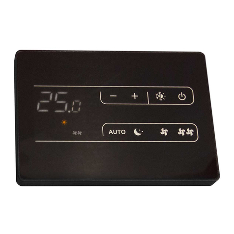
A Display
B Tasti e LED
I 6 LED visualizzano gli stati di funzionamento:
Indicazioni dei LED
Icone
Simbolo verde velocità minima
Simbolo verde velocità automatica
Simbolo verde velocità massima
Simbolo verde funzione Supersilent
Simbolo rosso riscaldamento
Simbolo blu raffrescamento
EN
The command makes environment temperature adjustment
completely autonomous through the adjustable set point,
from 5 to 40°C, of one of the 4 speeds, and the summer/
winter selection.
Since it is connected to the water temperature detection
probe inside the battery, it carries out the minimum
winter temperature function (30°C) and maximum summer
temperature function (20°C).
The control panel has function memory, so all the settings
are not lost in case of switch off or in the event of power
failure.
The commands cannot be installed on built-in versions.
After 20 seconds from the last action, the panel light
purposely dims down for greater comfort during night
time, and the environment temperature is shown on
the display. Maximum luminosity is restored when
pressing any key.
Description
A Display
B Keys and LED indicators
The 6 LED indicators show the operation status:
Display
Icons
Green symbol minimum speed
Green symbol automatic speed
Green symbol maximum speed
Green symbol Supersilent function
Red symbol heating
Blue symbol cooling

HELIOTERM INVERTER
Doc-0074814 Rev. 0
5
IT
Le varie funzioni vengono impostate attraverso 4 tasti:
Per la gestione del ventilconvettore attraverso il pannello
di controllo questo deve essere collegato alla rete elettrica.
Nel caso sia stato previsto un interruttore generale sulla
linea elettrica di alimentazione, questo deve essere
inserito.
Accendere l’impianto inserendo l’interruttore generale
Il numero di giri del ventilatore alla velocità massima può
essere incrementato da 1400 a 1700rpm attivando la funzione
Performance.
Con pannello spento tenere premuto per più di 10 secondi
il tasto per accedere al menu impostazione velocità
max. Sul display compare HS che sta per High speed
(1400rpm) e il led della velocità max pulsa lentamente.
Premendo brevemente il tasto compare PS, che sta per
Performance speed (1700rpm) e il led pulsa velocemente.
L’uscita dal menu avviene, salvando l’ultima impostazione
selezionata, automaticamente dopo 10 secondi dall’ultima
pressione dei tasti.
La funzione Performance non deve essere attivata sui
modelli Design Inverter S.
Funzione dei tasti
Accensione generale
Attivazione funzione Performance
Icone
Temp + consente di aumentare la temperatura
impostata
Temp - consente di diminuire la temperatura
impostata
Riscaldamento/Raffrescamento: consente di
commutare il modo di funzionamento tra
riscaldamento e raffrescamento (2 secondi)
Consente di attivare l’apparecchio, di
selezionare una delle 4 velocità o di porlo in
stand-by (2 secondi).
Per attivare l’apparecchio
Attivazione
Tasto Operazione Display
Premere il tasto mode/off Spento
Selezionare una delle 4 velocità
di funzionamento premendo
il relativo tasto mode/off. In
riscaldamento i simboli rimangono
accesi con setpoint superiore
alla temperatura ambiente,
spenti con setpoint inferiore. In
raffrescamento i simboli sono
accesi con setpoint inferiore alla
temperatura ambiente, spenti con
setpoint superiore.
EN
The various functions are set with the 4 keys:
To manage the fan coil through the control panel, it must
be connected to the mains.
In case of a general switch on the mains supply line, it
must be switched on.
Switch on the system with the main switch.
The maximum fan speed RPM can be increased from 1400
to 1700rpm activating the Performance function.
With the panel off hold for more than 10 seconds the
button to access the menu. The display shows HS that
means High speed (1400rpm) and the maximum speed
LED will blink slowly.
Briefly pressing the button PS appears, which means
Performance speed (1700rpm) and the LED blinks quickly.
Exit from the menu occurs, saving the last setting,
automatically 10 seconds after the last keypress.
The Performance function should not be enabled on
models Design Inverter S.
Key function
General switch on
Performance function activation
Icons
Temp + allows to increase set temperature
Temp - allows to decrease set temperature
Heating / Cooling : allows to switch operation
mode between heating and cooling (2 seconds)
Allows to activate the device, to select one of
the 4 speeds or to go in stand-by (2 seconds).
To activate the device
Activation
Key Operation Display
Press the mode/off key Off
Select one of the 4 operation
speeds by pressing the relative
mode/off key. When heating, the
symbols remain switched on when
the set point is higher than the
environment temperature; they are
switched off when the set point is
lower. When cooling, the symbols
are switched on when the set point
is lower than the environment
temperature; they are switched off
when the set point is higher.

HELIOTERM INVERTER
Doc-0074814 Rev. 0
6
IT
Impostazione modo di funzionamento
riscaldamento / raffrescamento
Tasto Operazione Display
Tenere premuto il tasto
Riscaldamento / Raffrescamento
per circa 2 secondi per commutare
il modo di funzionamento tra
riscaldamento e raffrescamento
visibile attraverso l’ accensione dei
2 simboli riscaldamento attivo o
raffrescamento attivo.
Stand by
Tasto Operazione Display
Tenere premuto il tasto mode/off
per circa 2 secondi . La mancanza
di qualsiasi segnalazione luminosa
dal display identifica lo stato di
“stand-by” (assenza di funzione).
Spento
Il range di regolazione va da 15 a 30 °C, con risoluzione di
1°C, ma sono consentiti anche i valori fuori scala di 5°C e
di 40°C.
Impostare tali valori solo per brevi periodi e poi regolare la
selezione su un valore intermedio.
Il comando è molto preciso, portarlo sul valore desiderato
ed attendere che il comando esegua la regolazione in base
alla effettiva temperatura ambiente rilevata.
Selezione della temperatura
Tasto Operazione Display
Impostare con l’ausilio dei due
tasti aumento e diminuzione il
valore di temperatura desiderato
in ambiente visualizzato sui 2 digit
del display.
Regolazione velocità di ventilazione
Tasto Operazione Display
Ad ogni pressione del pulsante
del tasto mode/off corrisponde
la variazione della velocità
del ventilatore tra supersilent,
minima, automatica e massima.
L’attivazione della funzione viene
segnalata dall’accensione del
relativo simbolo a display
La velocità supersilent darà luogo ad una forte
deumidificazione in raffrescamento e ad un funzionamento
solo radiante (con ventilatore spento ed elettrovalvola
azionata) in riscaldamento.
Impostando la velocità massima si ottiene immediatamente
il massimo della potenza erogabile sia in riscaldamento
che in raffreddamento.
Una volta raggiunta latemperatura ambiente desiderata
è consigliabile selezionare uno degli altri 3 modi di
funzionamento per ottenere un miglior confort termico ed
acustico.
EN
Heating / cooling operation mode setting
Key Operation Display
Keep Heating / Cooling pressed
down for about 2 seconds to switch
the operation mode between
heating and cooling, shown
through the 2 active heating or
active cooling symbols which
appear.
Stand by
Key Operation Display
Keep the mode/off key pressed for
about 2 seconds. The lack of any
light indicators from the display
indicates “standby” status (no
function).
Off
The adjustment range goes from 15 to 30 ℃, with 1℃
resolution, but over range values of 5°C and 40°C are also
consented.
Set these values only for brief periods, then adjust the
selection on an intermediate value.
The command is very precise; reach the desired value and
wait for the command to carry out the adjustment based
on the effective environment temperature detected.
Temperature selection
Key Operation Display
Set the desired temperature value,
shown on the 2 digits of the
display, with the aid of the two
increase and decrease keys.
Fan speed adjustment
Key Operation Display
At each pressing of the mode/
off key there is a corresponding
change in fan speed between
supersilent, minimum, automatic
and maximum.
Activation of the function is
indicated by the relative symbol
appearing on the display.
The supersilent speed causes strong de-humidification in
cooling and a radiating-only function (with fan off and
solenoid valve activated) in heating.
By setting maximum speed, the maximum distributable
power is immediately obtained both in heating as well as
cooling.
Once the desired environment temperature is reached, it
is advised to select one of the other 3 operation modes to
obtain the best thermal and acoustic comfort.

HELIOTERM INVERTER
Doc-0074814 Rev. 0
7
IT
Blocco tasti
Tasto Operazione Display
Premendo contemporaneamente
i tasti incremento e decremento
temperatura per 5 secondi si
attiva il blocco locale di tutti i
tasti, la conferma è data dalla
visualizzazione di bL.
Tutte le regolazioni vengono
inibite all’utente e alla pressione
di qualsiasi tasto compare bL.
Ripetendo la sequenza si ottiene lo
sblocco dei tasti.
Dopo un periodo di 20 secondi dall’ultima azione la
luminosità del pannello viene appositamente ridotta per
aumentare il confort nelle ore notturne e sul display viene
visualizzata la temperatura ambiente.
Se questa luminosità fosse ancora percepita come
fastidiosa è possibile far spegnere completamente il
display tenendo premuto per 20 secondi il pulsante
Riscaldamento/Raffreddamento fino alla comparsa a
display di .
Per ripristinare la normale luminosità minima andrà
premuto per 20 secondi il pulsante Riscaldamento/
Raffreddamento fino alla comparsa a display di .
Riduzione luminosità minima
Disattivazione
Tasto Operazione Display
Tenere premuto il tasto mode/off
per circa 2 secondi. La mancanza
di qualsiasi segnalazione luminosa
dal display identifica lo stato di
“stand-by” (assenza di funzione).
Spento
In caso di spegnimenti stagionali o per vacanze procedere
come segue:
Disattivare l’apparecchio.
Posizionare l’interruttore generale impianto su Spento
Spegnimento per lunghi periodi
EN
Key lock
Key Operation Display
By pressing the increase and
decrease keys simultaneously for
5 seconds, the local block of all
keys is activated, confirmed by the
display of bL.
All adjustments are prevented to
the user, and bL appears when
pressing any key.
Repeat the sequence to unlock the
keys.
After 20 seconds from the last action, the panel brightness
is purposely dimmed for greater comfort during night
time, and the room temperature is shown on the display.
If the brightness is still annoying one can switch the display
off completely by pressing and holding the Heating/Cooling
button for 20 seconds until appears on the display.
To restore the normal minimum brightness one must
press the Heating/Cooling button for 20 seconds until
appears on the display.
General switch on
Deactivation
Key Operation Display
Keep the mode/off key pressed for
about 2 seconds. The lack of any
light indicators from the display
indicates “standby” status (no
function).
Off
In case of seasonal switch-offs or for holidays, proceed as
follows:
Deactivate the device.
Switch Off the main switch.
Shutting down for long periods

HELIOTERM INVERTER
Doc-0074814 Rev. 0
8
IT
* Se la scheda rileva la sonda della temperatura
dell’acqua, presente sull’apparecchio, l’avvio avviene in
condizioni normali. Se la sonda non viene connessa è
possibile confermare il funzionamento privo di sonda,
premendo il pulsante Riscaldamento/Raffreddamento
per 5 secondi.
Segnalazioni d’errore
Display (lampeggiante)
Errore
Guasto della sonda di
temperatura ambiente
(AIR). Lampeggio dei 6
LED (allarme a riarmo
automatico).
Guasto della sonda
di rilevazione della
temperatura dell’acqua
(H2) posizionata nella
batteria principale.
Lampeggio dei 2 LED
(possibile riarmo
manuale)*.
Problema al motore
ventilatore (ad esempio
inceppamento dovuto
a corpi estranei, guasto
del sensore di rotazione,
azionamento del micro
di protezione griglia
dovuto all’operazione
di pulizia del filtro).
Lampeggio simultaneo
dei 4 LED (allarme a
riarmo automatico).
oppure
Richiesta di acqua
(calda o fredda) non
soddisfatta (sopra i 20°C
in raffreddamento, sotto
i 30°C in riscaldamento).
Il LED della funzione
selezionata lampeggia ed
il ventilatore è arrestato
finchè la temperatura
dell'acqua non raggiunge
un valore adeguato a
soddisfare la richiesta.
EN
* If the board detects the water temperature probe on
the device, start-up occurs in normal conditions. If the
probe is not connected, it is possible to confirm the
operation without a probe, by pressing Heating/Cooling
for 5 seconds.
Error indications
Display (flashing)
Error
Environment temperature
probe fault (AIR). Flashing
of 6 LED indicators
(automatic re-arm alarm).
Fault in the water
temperature detection
probe (H2) positioned in
the main battery. Flashing
of 2 LED indicators
(possible manual re-
arm)*.
Problem with the fan
engine (for example,
jamming due to
extraneous bodies, fault
in the rotation sensor,
activation of the grid
protection micro switch
due to filter cleaning
operation). Simultaneous
flashing of 4 LED
indicators (automatic re-
arm alarm).
or
Water requirement (hot
or cold) not satisfactory
(above 20°C in cooling,
below 30°C in heating).
The selected function LED
indicator flashed, and the
fan stops until the water
temperature does not
reach an adequate value
to satisfy the request.

HELIOTERM INVERTER
Doc-0074814 Rev. 0
9
C
CS035
SPARE
T_ACQUA
V10
TERMOSTATO
E_VALVE
FAN_COIL
PRG
LOCK
DL1
COMEVV1V2V3V4
E/I
LN
GDBtech.com
ED
IT
Nel caso si renda necessario invertire la posizione degli
attacchi idraulici della batteria dal lato sinistro a quello
destro dell’apparecchio la scatola dei collegamenti
elettrici viene anch’essa invertita ma essendo il motore
del ventilatore ed il microinterruttore sicurezza griglia
vincolati nella posizione originale si rende necessario
utilizzare l’apposito kit 20069415 disponibile come
accessorio.
Il cavo, dotato di connettori maschio/femmina va collegato
nel lato destro al motore e nel lato sinistro al connettore
rapido del motore presente sulla scheda (rif.D).
Inoltre i due terminali provenienti dal microinterruttore
sicurezza griglia vanno prolungati e connessi nel lato
sinistro al contatto S1 presente sulla scheda (rif.E).
I cavi vanno fatti passare nella parte posteriore
dell’apparecchio attraverso lo specifico foro (rif.C).
Collegamento motore nelle versioni con
attacchi idraulici a destra
EN
In the event one needs to invert the position of the hydraulic
battery connections from the left side to the right side of
the device, the electric connections box is also inverted,
but since the fan motor and the grid safety microswitch
are constrained in the original position, one must use the
special kit 20069415, available as an accessory.
The cable, equipped with male/female connectors, must
be connected on the right side to the motor and on the
left side to the quick connector of the motor present on
the board (ref.D).
Also, the two terminals from the grid safety microswitch
must be extended and connected on the left side to
contact S1 present on the board (ref.E).
The cables are fed through the back of the device through
the specific hole (ref.C).
Water connection on the right side versions
motor connection

HELIOTERM INVERTER
Doc-0074814 Rev. 0
10
IT EN

HELIOTERM INVERTER
Doc-0074814 Rev. 0
11
IT EN

HELIOTERM INVERTER
Doc-0074814 Rev. 0
12
RIELLO S.p.A. - 37045 Legnago (VR)
tel. +39 0442 630111 - fax +39 0442 22378
www.riello.it
IT
Poiché l’Azienda è costantemente impegnata nel continuo perfezionamento di tutta la sua produzione, le
caratteristiche estetiche e dimensionali, i dati tecnici, gli equipaggiamenti e gli accessori, possono essere soggetti
a variazione.
EN
As the manufacturer is constantly improving its products, the aesthetic or dimensional features, the technical data,
the equipment and accessories indicated could be subject to variations.
Table of contents
Other Riello Control Panel manuals

Riello
Riello Touchscreen N User manual

Riello
Riello RIELLOtech CLIMA TOP 4031065 User manual

Riello
Riello CPD 35 User manual

Riello
Riello 4030011 User manual

Riello
Riello CPD 35 User manual

Riello
Riello Thermital TBOX BASIC ACS Technical manual

Riello
Riello Wired Touch panel User manual

Riello
Riello CBD 25 User manual

Riello
Riello NexSirius User manual

Riello
Riello RIELLOtech PRIME User manual