BFT LEO MV D User manual

ISTRUZIONI D’USO E DI INSTALLAZIONE
INSTALLATION AND USER’S MANUAL
INSTRUCTIONSD’UTILISATIONETD’INSTALLATION
INSTALLATIONS-UND GEBRAUCHSANLEITUNG
INSTRUCCIONES DE USOY DE INSTALACION
INSTRUÇÕES DE USO E DE INSTALAÇÃO
I
GB
F
D
E
P
QUADRO COMANDO
CONTROL PANEL
CENTRALE DE COMMANDE
STEUERUNG
CUADRO DE MANDOS
QUADRO DE COMANDO
Via Lago di Vico, 44
36015 Schio (VI)
Tel.naz. 0445 696511
Tel.int. +39 0445 696533
Fax 0445 696522
Internet: www.bft.it
E-mail: [email protected]
LEO MV D
D811512 ver. 03 21-05-07
8027908 2 9 7 2 3 5

2 -LEO MV D - Ver. 03
D811512_03

LEO MV D - Ver. 03 - 3
D811512_03
USER’S MANUAL ENGLISH
MANUALE D’USO ITALIANO
Nel ringraziarVi per la preferenza accordata a questo prodotto, la ditta è certa che da
esso otterrete le prestazioni necessarie al Vostro uso.
Leggete attentamente l’opuscolo ”Libretto istruzioni” che lo accompagna in quanto
esso fornisce importanti indicazioni riguardanti la sicurezza, l’installazione, l’uso e la
manutenzione.Questo prodotto risponde alle norme riconosciute della tecnica e delle
disposizioni relative alla sicurezza. Confermiamo che esso è conforme alle seguenti
direttive europee:89/336/CEE, 73/23/CEE, 98/37/CEE e loro modifiche successive.
1) GENERALITÁ
Il quadro comandi LEO MV D viene fornito dal costruttore con settaggio standard.
Qualsiasi variazione, deve essere impostata mediante il programmatore a display
incorporato o mediante programmatore palmare universale. La Centralina supporta
completamenteilprotocolloEELINKcompresal’autoalimentazionedelprogrammatore
da centralina.
È disponibile in due versioni: per installazione esterna, all’interno della scatola SD, o
montata e precablata all’interno dell’attuatore.
Le caratteristiche principali sono:
- Rallentamento della velocità all’accostamento.
- Regolazione elettronica della coppia.
- Frenatura elettrodinamica regolabile.
- Ingressi di fine-corsa chiusura / apertura
- Ingressi separati per le sicurezze.
- Ingresso orologio.
- Ingressso collegamento protocollo seriale (opzionale).
- Ricevitore radio incorporato
2) FUNZIONI
PER L’INSTALLATORE: compilare la tabella con in parametri impostati al fine di
facilitare future modifiche e manutenzioni.
Tra parentesi quadre [ ] sono indicati i valori preimpostati.
MENU PARAMETRI
Tempo Chiusura Automatica [10s] _____
Spazio rallentamento [5] _____ Impostabile solo con BARRIERA=1
Tempo allarme [30s] _____
Zona [0] _____
Coppia rallentamento [99%] _____ Impostabile solo con BARRIERA=1
Coppia apertura [70%] _____ Impostabile solo con BARRIERA=1
Coppia chiusura [70%] _____ Impostabile solo con BARRIERA=1
Freno [52%] _____
Encoder [1] _____ Impostabile solo con BARRIERA=0
Tipo di barriera [1] _____
MENU Logiche
TCA [ON] _____
3 Passi [ON] _____
Blocca Impulsi apertura [ON] _____
Blocca Impulsi TCA [OFF] _____
Pre allarme [OFF] _____
Fotocellule in apertura [ON] _____
Chiusura rapida [OFF] _____
Allarme SCA [ON] _____
Master/Slave [OFF] _____
Test fotocellule (PHOT) [OFF] _____
Test costa sensibile (BAR) [OFF] _____
Codice fisso [OFF] _____
Programmazione radiocomandi [ON] _____
3) DEMOLIZIONE
Attenzione: Avvalersi esclusivamente di personale qualificato.
L’eliminazionedeimaterialivafattarispettandolenormevigenti.Nelcasodidemolizione,
non esistono particolari pericoli o rischi derivanti dal prodotto stesso. È opportuno, in
caso di recupero dei materiali, che vengano separati per tipologia (parti elettriche - rame
- alluminio - plastica - ecc.).
4) SMANTELLAMENTO
Attenzione: Avvalersi esclusivamente di personale qualificato.
Nel caso la centralina venga smontata per essere poi rimontata in altro sito bisogna:
• Togliere l’alimentazione e scollegare tutto l’impianto elettrico.
• Nel caso alcuni componenti non possano essere rimossi o risultino danneggiati,
provvedere alla loro sostituzione.
AVVERTENZE
Il buon funzionamento dell’operatore è garantito solo se vengono rispettati i dati
riportatiinquestomanuale.Ladittanonrispondedeidannicausatidall’inosservan-
za delle norme di installazione e delle indicazioni riportate in questo manuale.
Le descrizioni e le illustrazioni del presente manuale non sono impegnative.
Lasciando inalterate le caratteristiche essenziali del prodotto, la Ditta si riserva
di apportare in qualunque momento le modifiche che essa ritiene convenienti
per migliorare tecnicamente, costruttivamente e commercialmente il prodotto,
senza impegnarsi ad aggiornare la presente pubblicazione.
Thank you for buying this product, our company is sure that you will be more than
satisfied with the product’s performance. The product is supplied with a “Warnings”
leaflet and an “Instruction booklet”. These should both be read carefully as they
provide important information about safety, installation, operation and maintenance.
This product complies with the recognised technical standards and safety regulations.
We declare that this product is in conformity with the following European Directives:
89/336/EEC and 73/23/EEC, 98/37/EEC (and subsequent amendments).
1) GENERAL OUTLINE
TheLEO MV D control panel is supplied bythe manufacturerwith standardsetting.Any
alteration must be set by means of the incorporated display programmer or by means
of universal palmtop programmer.The Control unit completely supports the EELINK
protocol, including the programmer self-supply from the control unit. It is available in
two versions:one for external installation, inside the SD box, the other fitted and pre-
wired inside the controller.
Its main characteristics are:
- Slow down of end-of-run speed.
- Electronic torque setting
- Adjustable electrodynamic braking
- Closing / opening limit-switch inputs
- Separate inputs for safety devices
- Clock input
- Serial protocol connection input (Option).
- Incorporated radio receiver
2) FUNCTIONS
FOR THE INSTALLER: Fill in the table with the parameters set, in order to facilitate
future modifications and maintenance operations.
The preset values are indicated between square brackets [ ].
PARAMETER MENU
Automatic ClosingTime (TCA) [10s] _____
Slow-down Distance [5] _____ Can be set with “Barrier”=1 only.
Alarm time [30s] _____
Zone [0] _____
Slow-down torque [99%] _____ Can be set with “Barrier”=1 only.
Opening torque [70%] _____ Can be set with “Barrier”=1 only.
Closing torque [70%] _____ Can be set with “Barrier”=1 only.
Brake [52%] _____
Encoder [1] _____ Can be set with “Barrier”=0 only.
Type of barrier [1] _____
Logic MENU
TCA [ON] _____
3 Steps [ON] _____
Impulse locking [ON] _____
TCA impulse locking [OFF] _____
Pre-alarm [OFF] _____
Photocells on opening [ON] _____
Rapid closing [OFF] _____
SCA alarm [ON] _____
Master/slave [OFF] _____
Photocell test [OFF] _____
Electric edge test [OFF] _____
Fixed code [OFF] _____
Radio transmitter programming [ON] _____
3) SCRAPPING
Warning:Thisoperationshouldonlybecarriedoutbyqualifiedpersonnel.Materials
must be disposed of in conformity with the current regulations. In case of scrapping,
the automation devices do not entail any particular risks or danger.In case of materials
to be recycled, these should be sorted out by type (electrical components, copper,
aluminium, plastic etc.).
4) DISMANTLING
Warning:This operation should only be carried out by qualified personnel.
When the control unit is disassembled to be reassembled on another site, proceed
as follows:
• Disconnect the power supply and the entire electrical installation.
• In the case where some of the components cannot be removed or are damaged,
they must be replaced.
WARNINGS
Correct controller operation is only ensured when the data contained in the
present manual are observed.The company is not to be held responsible for
any damage resulting from failure to observe the installation standards
and the instructions contained in the present manual.
Thedescriptionsandillustrationscontainedinthepresentmanualarenotbinding.
The Company reserves the right to make any alterations deemed appropriate
for the technical, manufacturing and commercial improvement of the product,
while leaving the essential product features unchanged, at any time and without
undertaking to update the present publication.

LEO MV D - Ver. 03 - 11
D811512_03
INSTALLATION MANUAL ENGLISH
Thankyouforbuyingthis product, our company is sure that you will be more
than satisfied with the product’s performance. The product is supplied with
a “Warnings” leaflet and an “Instruction booklet”. These should both be
read carefully as they provide important information about safety, installa-
tion,operationand maintenance. This product complieswiththerecognised
technical standards and safety regulations. We declare that this product
is in conformity with the following European Directives: 89/336/EEC and
73/23/EEC, 98/37/EEC (and subsequent amendments).
1) GENERAL SAFETY
WARNING! An incorrect installation or improper use of the product
can cause damage to persons, animals or things.
• The “Warnings” leaflet and “Instruction booklet” supplied with this
product should be read carefully as they provide important information
about safety, installation, use and maintenance.
• Scrap packing materials (plastic, cardboard, polystyrene etc) according
to the provisions set out by current standards. Keep nylon or polystyrene
bags out of children’s reach.
• Keep the instructions together with the technical brochure for future
reference.
• This product was exclusively designed and manufactured for the use
specified in the present documentation. Any other use not specified in
this documentation could damage the product and be dangerous.
• The Company declines all responsibility for any consequences resulting
from improper use of the product, or use which is different from that
expected and specified in the present documentation.
• Do not install the product in explosive atmosphere.
• The construction components of this product must comply with the
following European Directives: 89/336/CEE, 73/23/EEC, 98/37/EEC
and subsequent amendments. As for all non-EEC countries, the above-
mentioned standards as well as the current national standards should
be respected in order to achieve a good safety level.
• The Company declines all responsibility for any consequences resulting
fromfailuretoobserveGoodTechnicalPracticewhenconstructingclosing
structures(door,gatesetc.),aswellasfromanydeformationwhichmight
occur during use.
• The installation must comply with the provisions set out by the following
EuropeanDirectives:89/336/CEE,73/23/EEC,98/37/EECandsubsequent
amendments.
• Disconnect the electrical power supply before carrying out any work on
the installation. Also disconnect any buffer batteries, if fitted.
• Fit an omnipolar or magnetothermal switch on the mains power supply,
having a contact opening distance equal to or greater than 3,5 mm.
• Check that a differential switch with a 0.03A threshold is fitted just before
the power supply mains.
• Check that earthing is carried out correctly: connect all metal parts for
closure (doors, gates etc.) and all system components provided with an
earth terminal.
• Fitallthesafetydevices(photocells,electricedgesetc.)whichareneeded
toprotecttheareafromanydangercausedbysquashing, conveyingand
shearing.
• Position at least one luminous signal indication device (blinker) where it
can be easily seen, and fix a Warning sign to the structure.
• The Company declines all responsibility with respect to the automation
safetyandcorrect operation when other manufacturers’ components are
used.
• Only use original parts for any maintenance or repair operation.
• Do not modify the automation components, unless explicitly authorised
by the company.
• Instruct the product user about the control systems provided and the
manual opening operation in case of emergency.
• Do not allow persons or children to remain in the automation operation
area.
• Keep radio control or other control devices out of children’s reach, in
order to avoid unintentional automation activation.
• Theusermustavoidanyattempttocarryoutworkorrepairontheautoma-
tion system, and always request the assistance of qualified personnel.
• Anything which is not expressly provided for in the present instructions,
is not allowed.
• Installation must be carried out using the safety devices and controls
prescribed by the EN 12978 Standard.
2) GENERAL OUTLINE
The LEO MV D control panel is supplied by the manufacturer with standard
setting. Any alteration must be set by means of the incorporated display
programmer or by means of universal palmtop programmer. The Control
unit completely supports the EELINK protocol.
Itis availableintwo versions: oneforexternal installation,insidethe SDbox,
the other fitted and pre-wired inside the controller.
Its main characteristics are:
- Slow down of end-of-run speed.
- Electronic torque setting
- Adjustable electrodynamic braking
- Closing / opening limit-switch inputs
- Separate inputs for safety devices
- Clock input
- Serial protocol connection input (optional)
- Incorporated radio receiver
The board is provided with a terminal board which can be pulled out for
easier maintenance or replacement. The board is supplied with a series of
pre-wired jumpers to facilitate the installer’s work.
The jumpers relate to the following terminals: 21-23, 21-24 and 21-30. If the
above-mentioned terminals are in use, remove their respective jumpers.
3) TECHNICAL SPECIFICATIONS
Power supply: .................................................................230V±10% 50Hz*
Mains/low voltage insulation: ........................................ > 2MOhm 500V
Dielectric strength: ........................mains/low voltage 3750V~for 1 minute
Motor output current: .................................................................... 1.5Amax
Maximum motor power:..................................................................... 750W
Supply to accessories: ...................................... 24V~(1A max absorption)
Gate-open warning light: ..................................................... 24V~3W max
Blinker: ................................................................................230V 40W max
Dimensions: ..............................................................................see figure 1
Fuses: .......................................................................................see figure 2
(* other voltages available on request)
4) TERMINAL BOARD CONNECTIONS (Fig.3)
WARNING – During the wiring and installation operations, refer to the cur-
rent standards as well as principles of good technical practice.
The cables must be tied by additional fastening next to the terminals, by
means of clips for example.
All the operator wiring operations must be carried out by qualified personnel.
JP1
1 GND terminal
2-3 Single-phase mains supply 230V±10% 50Hz (2=N) (3=L)
JP2
4-5 Blinker connection (mains voltage) 40W Max.
6-7-8-9 Motor connection:
6 operation 1 + capacitor
7 common (blue)
8 operation 2
9 capacitor
JP3
10-11 Output 24V~ 1A max – power supply for photocells or other
devices.
12-13 Gate-open warning light output (24V 3W max)
JP4 Barrier status output
20-18 Closed Contact with barrier raised
20-19 Closed Contact with barrier lowered
Contact switching for barrier status control.
To be used in Parky systems (see paragraph 13)
JP5 Encoder connection
WARNING! The maximum length of the connection cable of
the encoder should not exceed 3.00 mt.
JP8
21-22 Open-Close button (N.O. Start), key selector.
21-23 Block button (N.C. Stop). If not used, leave jumped.
21-24 Photocell input (N.C.). If not used, leave jumped.
21-25 Openinglimitswitch connection (N.C. SWO). Ifnotused,leave
jumped.
21-26 Closing limit switch connection (N.C. SWC). If not used, leave
jumped.
21-27 Not used
21-28 Open-Button connection (N.O. Open)
21-29 Close-Button connection (N.O. Close)
21-30 Rubber edge connection (N.C.). If not used, leave jumped.
21-31 Connection of clock input (N.O.). If the contact connected isConnection of clock input (N.O.). If the contact connected is
open, the barrier closes and gets ready for normal operation.
If the contact is closed (N.C.), the barrier opens and remains
open until contact opening.
JP9
32 Photocell check input (PHOT FAULT) (see Fig. 3)
33 Electric edge check input (EDGE FAULT) (see Fig. 3)
38-39 Antenna input for radio-receiver (38 signal - 39 braid). Cable
RG58.

12 -LEO MV D - Ver. 03
D811512_03
INSTALLATION MANUAL
5) PROGRAMMING
The control panel provided with a microprocessor is supplied with function
parameters preset by the manufacturer, suitable for standard installations.
Thepredefinedparameterscanbealteredbymeansofeithertheincorporated
display programmer or universal palmtop programmer.
Inthecasewhereprogrammingiscarried outby meansof universalpalmtop
programmer, carefully read the instructions relating to universal palmtop
programmer, and proceed in the following way.
Connect the universal palmtop programmer to the control unit through the
UNIFLATaccessory(Seefig.4).Enterthe“CONTROLUNITS”menu,andthe
“PARAMETERS”submenu,thenscrollthedisplayscreenfulsusingtheup/down
arrows, and set the numerical values of the parameters listed below.
For the function logics, refer to the “LOGIC” submenu.
In the case where programming is carried out by means of the incorporated
programmer, refer to Fig. A and B and to the “configuration” paragraph.
6) CONFIGURATION
The display programmer is used to set all the LEO MV D control panel
functions.
The programmer is provided with three pushbuttons for menu scrolling and
function parameter configurations:
+ menu scrolling/value increment key
- menu scrolling/value reduction key
OK Enter (confirm) key
The simultaneous pressure of the + and – keys is used to exit the active
menu and move to the preceding menu.
If the + and – keys are pressed simultaneously at the main menu level (pa-
rameters, logics, radio, language, autosetting), programming is exited and
the display is switched off (the OK message is displayed).
The modifications made are only set if the OK key is subsequently pres-
sed.
When the OK key is pressed for the first time, the programming mode is
entered.
The following pieces of information appear on the display at first:
- Control unit Software version
- Number of total manoeuvres carried out (the value is expressed in
thousands, therefore the display constantly shows 0000 during the first
thousand manoeuvres)
- Numberofmanoeuvrescarriedoutsincethelatestmaintenanceoperation
(the value is expressed in thousands, therefore the display constantly
shows 0000 during the first thousand manoeuvres)
- Number of memorised radio control devices.
When the OK key is pressed during the initial presentation phase, the first
menu (parameters) can be accessed directly.
Here follows a list of the main menus and the respective submenus avai-
lable.
The predefined parameter is shown between square brackets [ 0 ].
The writing appearing on the display is indicated between round brackets.
Refer to Figures A and B for the control unit configuration procedure.
6.1) Parameter Menu (PARAM)
1 - Automatic Closing Time (TCA) [ 10s ]
Set the numerical value of the automatic closing time from 1 to 180
seconds.
2 - Slow-down Distance (Cm. rall) [ 5]
Set the required slow-down distance for opening and closing between
1and 90.
NOTE: power failure, reset, or manual gate release, the control panel
carries out a complete manoeuvre at reduced speed, in order to learn
the length of stroke.
3- Alarm time (alarm. time) [ 30s ]
In the case of obstacle detection or photocell engagement, at the end of
the time set (ranging from 10s to 240s) the SCA contact is closed. The
contact is subsequently opened by the STOP command or by triggering
of the closing limit switch. Only active when the SCA Alarm logic is set
to OFF.
4- Zone (zone) [ 0 ]
Set the zone number between a minimum value of 0 and a maximum
value of 128. See paragraph 8on “Serial connection”.
5- Slow-down torque (slud torque ) [ 99% ]
Set the motortorquevalue during theslow-downphasebetween 0% and
99%.
6- Opening torque (open torque) [ 70% ]
Set the motor opening torque value between 1% and 99%.
7- Closing torque (cls. torque) [ 70% ]
Set the motor closing torque value between 1% and 99%.
8 - Brake (Brake) [ 52% ]
Set the required brake value between 0 and 99%, compatibly with the
weight of the rod and the existing stresses.
9 - Encoder (Encoder) [ 1 ]
0: encoder disabled: timed slow-down, obstacle detection function not
active. (The encoder can be disconnected).
1: encoder enabled: slow-down and obstacle detection by means of
encoder (default).
WARNING: Check that the impact force value measured at
thepoints establishedby theEN 12445 standard is lowerthan that
specified in the EN 12453 standard.
Incorrect sensitivity setting can cause injuries to persons or
animals, or damage to things.
10- Type of barrier (barrier) [1]
0: MOOVI 30RMM/50RMM mod. barrier
1: MOOVI 30S mod. barrier
2: BGV mod. barrier
Factory-preset value, in case of maintenance or malfunctions, check the
correspondence between the setting and the barrier model.
With the MOOVI 30RMM/50RMM barrier (0) , the following functions
are not active:
- slow down
- torque setting (the barrier always works at maximum torque).
With the BGV barrier (2) , the following functions are not active:
- slow down
- torque setting (the barrier always works at maximum torque).
obstacle detection.
6.2) Logic Menu (logic.)
- TCA ( tca ) [ ON ]
ON: Activates automatic closing
OFF: Excludes automatic closing
- 3 Steps (3 step) [ ON ]
ON: Enables 3-step logic. A start impulse has the following effects:
barrier closed:closed:...........................................................................opens
on opening: .............................stops and enters TCA (if configured)
barrier open:open:............................................................................ closes
on closing:.........................................stops and reverses movement
after stopping:...........................................................................opens
OFF: Disables 3-step logic
- Opening Impulse lock (Ibl open) [ ON ]
ON: The Start impulse has no effect during the opening phase.
OFF: The Start impulse becomes effective during the opening phase.
- Impulse lock TCA (ibl TCA ) [ OFF ]
ON: The Start impulse has no effect during the TCA dwell period.
OFF: The Start impulse becomes effective during the TCA dwell period.
- Pre alarm (pre-alarM) [ OFF ]
ON: The blinker comes on about 3 seconds before the motor starts.
OFF The blinker comes on at the same time as the motor starts.
- Photocells on opening (photc. open) [ ON ]
ON: In case of obscuring, this excludes photocell operation on opening.
During the closing phase, it immediately reverses the motion.
OFF: In case of obscuring, the photocells are active both on opening and
on closing. When a photocell is obscured on closing, it reverses the
motion only after the photocell is disengaged.
- Rapid closing (fast cls ) [ OFF ]
ON: Closes barrier after photocell disengagement, before waiting for thebarrier after photocell disengagement, before waiting for theafter photocell disengagement, before waiting for the
end of the TCA (automatic closing time) set.
OFF: Command not entered.
- SCA Alarm (SCA alarm) [ ON ]
ON: The SCA contact (terminals 12-13) behaves as follows:
with barrier open and on opening:..contact closed (warning light on)
with barrier closed:contact open.............................(warning light off)
on closing:........................................... intermittent contact (blinking)
OFF: The SCA contact closes according to the modes set by the Alarm
Time parameter.
- Master/Slave (Master) [ OFF ]
ON: The control panel is set as Master in a centralised connection (see
Paragraph 7).
OFF: The control panel is set as Slave in a centralised connection (see
Paragraph 7).
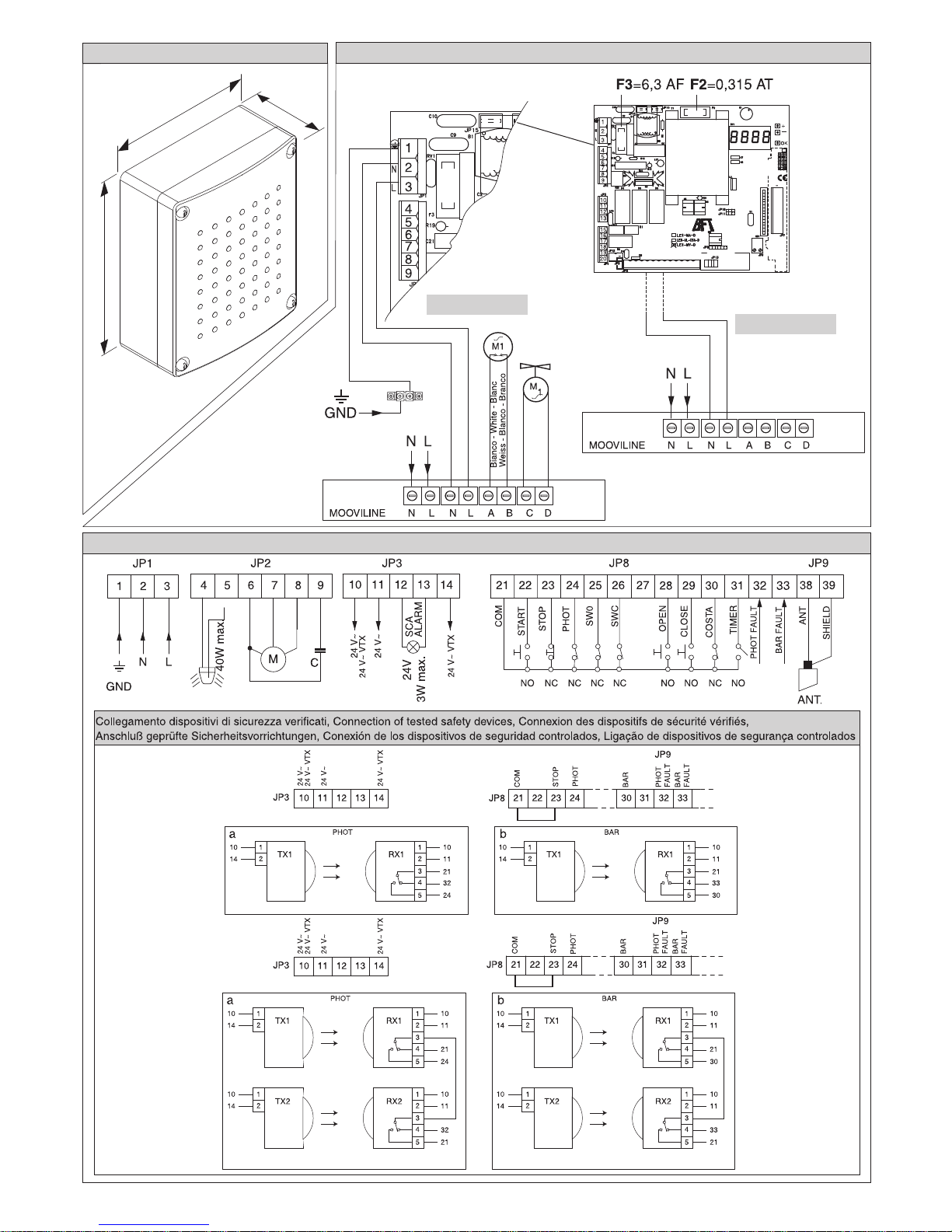
- Photocell test (test phot) [ OFF ]
ON: Activates photocell check (see Fig. 3)
OFF: Deactivates photocell check
- Electric edge test (test bar) [ OFF ]
ON: Activates electric edge check (see Fig. 3)
OFF: Deactivates electric edge check
- Fixed code (fixed code) [ OFF ]
ON: The receiver is configured for operation in fixed-code mode, see
paragraph on “Radio Transmitter Cloning”.
OFF: The receiver is configured for operation in rolling-code mode, see
paragraph on “Radio Transmitter Cloning”.
ENGLISH

LEO MV D - Ver. 03 - 13
D811512_03
INSTALLATION MANUAL ENGLISH
- Radio transmitter programming (radio prog) [ ON ]
ON: This enables transmitter storage via radio:
1 – First press the hidden key (P1) and then the normal key (T1, T2,
T3 or T4) of a transmitter already memorised in standard mode by
means of the radio menu.
2 – Within 10s press the hidden key (P1) and the normal key (T1, T2,
T3 or T4) of a transmitter to be memorised.
The receiver exits the programming mode after 10s, other new trans-
mitters can be entered before the end of this time.
This mode does not require access to the control panel.
OFF: This disables transmitter storage via radio.
The transmitters can only be memorised using the appropriate Radio
menu.
6.3) Radio Menu (radio)
- Add start (add start)
Associates the required key to Start command
- Read (read)
Checks one key of a receiver; if stored it displays a message showing
the receiver number in the memory location (from 01 to 64), and the key
number (T1, T2, T3 or T4).
- Eliminate list (erease 64)
WARNING!Completelyremovesallmemorisedradiocontroldevicesfrom
the receiver memory.
- Receiver code reading (RX code)
This displays the code entered in the receiver.
6.4) Language Menu (Language)
Allows you to set the language on the display programmer.
5 languages are available:
- ITALIAN (TA)
- FRENCH (FRA)
- GERMAN (DEU)
- ENGLISH (ENG)
- SPANISH (ESP)
6.5) MENU DEFAULT (DEFAULT)
Restores the preset default values on the control unit. After restoring, a new
autoset operation must be carried out.
6.6) DIAGNOSTICS AND MONITORING
The display on the LEO MV D panel shows some useful information, both
during normal operation and in the case of malfunctions.
Diagnostics:
In the case of malfunctions, the display shows a message indicating which
device needs to be checked:
STRT = STARTinput activation
STOP = STOP input activation
PHOT = PHOT input activation
FLT = FAULT input activation for checked photocells
SWO = input activation OPENING LIMIT SWITCH
SWC = input activation CLOSING LIMIT SWITCH
OPEN = OPEN input activation
CLS = CLOSE input activation
BAR = input activation SAFETY EDGE
TIME = TIMER input activation
In the case where an obstacle is found, the LEO MV D panel stops the door
and activates a reverse manoeuvre; at the same time the display shows the
“BAR” message.
6.7) Statistics
Having connected the universal palmtop programmer to the control unit,
enter the CONTROL UNIT / STATISTICS menu and scroll the screenful
showing the statistical parameters:
- Board microprocessor software version.
- Number of cycles carried out. If motors are replaced, count the number
of manoeuvres carried out up to that time.
- Number of cycles carried out from the latest maintenance operation.
It is automatically set to zero after each self-diagnosis or parameter writing.
- Date of latest maintenance operation. To be updated manually from the
appropriate menu “Update maintenance date”.
- Installation description. 16 characters can be entered for installation
identification.
7) CONNECTION TO PARKY CAR-PARK MANAGEMENT SYSTEM
Theboard isprovidedwith anoutput(terminal JP4)for controlling thebarrier
status, configured as follows (Fig.7):
contact closed between terminals 19 and 20 with barrier lowered
contact closed between terminals 18 and 20 with barrier raised.
8) SERIAL CONNECTION USING SCS1 BOARD (Fig.5)
The LEO-MV-D control panel allows several automation units (SCS1) to be
connected in a centralised way by means of appropriate serial inputs and
outputs. This makes it possible to use one single command to open and
close all the automation units connected.
Following the diagram in Fig.5, proceed to connecting all the LEO-MV-D
control panels, exclusively using a telephone-type line.
Shoulda telephonecable withmorethan onepair beneeded,it isindispens-
able to use wires from the same pair.
Thelengthofthetelephonecablebetweenoneapplianceandthenextmust
not exceed 250 m.
At this point, each of the LEO-MV-D control panels must be appropriately
configured,bysettingaMASTER unit first of all, which will have control over
all the others, to be necessarily set as SLAVE (see logic menu).
Also set the Zone number (see parameter menu) between 0 and 127.
Thezonenumber allows you to creategroupsofautomationunits, each one
answering to the Zone Master unit. Each zone can only be assigned one
Master unit, the Master unit in zone 0 also controls the Slave units in
the other zones.
8.1) Opposite barriers/gates (Fig.6)
Only with 3.7 or later microprocessor version.
By means of a serial connection, it is also possible to obtain centralised
control of two opposite barriers/gates.
Inthiscase,the MasterM1controlpanelwill simultaneouslymanageclosing
and opening for the Slave M2 control panel.
SETTING REQUIRED FOR OPERATION:
- MASTER board: zone=128, master=ON
- SLAVE board: zone=128, master=OFF
WIRING REQUIRED FOR OPERATION:
- The MASTER and SLAVE control units are interconnected through the 4
wires (RX/TX) for the SCS1 interface boards;
- All the activation controls, as well as the remote controls must refer to the
MASTER board;
- All the photocells (checked or unchecked) must be connected to the MAS-
TER control panel;
- The safety edges (checked or unchecked) of the MASTER leaf must be
connected to the MASTER control unit;
- The safety edges (checked or unchecked) of the SLAVE leaf must be con-
nected to the SLAVE control unit.
9) SCRAPPING
Materials must be disposed of in conformity with the current regulations.
In case of scrapping, the automation devices do not entail any particular
risks or danger. In case of recovered materials, these should be sorted out
by type (electrical components, copper, aluminium, plastic etc.).
10) DISMANTLING
WARNING: before opening the door, make sure that the spring has
been unloaded (rod at 43°). Whentheautomation system is disassembled
to be reassembled on another site, proceed as follows:
- Disconnect the power supply and the entire electrical installation.
- Remove the actuator from its fixing base.
- Disassemble all the installation components.
- In the case where some of the components cannot be removed or are
damaged, they must be replaced.
WARNINGS
Correctcontrolleroperationisonlyensuredwhenthedatacontainedin
thepresentmanualareobserved.Thecompanyisnottobeheldrespon-
sible for any damage resulting from failure to observe the installation
standards and the instructions contained in the present manual.
The descriptions and illustrations contained in the present manual are
not binding. The Company reserves the right to make any alterations
deemed appropriate for the technical, manufacturing and commercial
improvement of the product, while leaving the essential product fea-
tures unchanged, at any time and without undertaking to update the
present publication.

14 -LEO MV D - Ver. 03
D811512_03

LEO MV D - Ver. 03 - 15
D811512_03

36 -LEO MV D - Ver. 03
D811512_03
Fig.1 Fig.2
Fig.3
236
194
100
* MOOVI * BGV

LEO MV D - Ver. 03 - 37
D811512_03
Fig. 4
LEO-MV-D
UNIDA
UNIFLAT
Contatti
Contacts
Contacts
Kontakte
Contactos
Contatos
UNITRC
Contatti
Contacts
Contacts
Kontakte
Contactos
Contatos
UNIFLAT
Contatti
Contacts
Contacts
Kontakte
Contactos
Contatos
Contatti
Contacts
Contacts
Kontakte
Contactos
Contatos
1
34
2
1
34
212
34
12
34
UNIPOWER
UNIFLAT
UNIFLAT
UNIMITTO UNITRC
UNIMITTO
UNITRC
P1
T1
Led T2
TRC 1-2
P1
P1
T1
T2
T3
T4
P1
P1
T1
Led T2
P1
P1
T1
T2
T3
T4
P1P1
P1
Contatti
Contacts
Contacts
Kontakte
Contactos
Contatos
Programmatore palmare universale
Universal palmtop programmer
Programmateur de poche universel
Universellen Palmtop-Programmierer
Programador de bolsillo universal
Programador palmar universal

38 -LEO MV D - Ver. 03
D811512_03
Fig. 6
Fig. 5
SCS1 SCS1 SCS1
Max. 250m
TX1
TX2
RX1
RX2
TX1
TX2
RX1
RX2
TX1
TX2
RX1
RX2
SCS1

LEO MV D - Ver. 03 - 39
D811512_03
Fig. 7
JP4
18 19 20
NO NC COM
JP4
18 19 20
NO NC COM

Table of contents
Other BFT Control Panel manuals