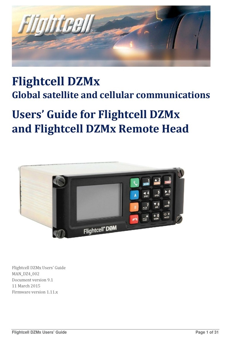
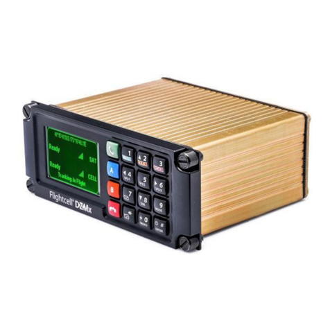
Flightcell DZMx User manual

Flightcell International Ltd
DZMx Installation Manual
Firmware Version 3.2.x
MAN_DZ4_001
Document Version 24.0
21 July 2019

Page 2

Page 3
CONTENTS
SECTION 1: INTRODUCTION.............................................................................................................. 4
APPLICABILITY OF THIS MANUAL .................................................................................................................. 4
SUPPLIED DOCUMENTATION....................................................................................................................... 4
OVERVIEW OF DZMX FUNCTIONS ............................................................................................................... 4
SECTION 2: DZMXEQUIPMENT .......................................................................................................... 6
CONNECTORS ........................................................................................................................................... 6
THE ETHERNET/USB CONNECTOR MODULE................................................................................................. 6
SECTION 3: DZMXSPECIFICATIONS.................................................................................................. 7
VERSIONS AND PART NUMBERS.................................................................................................................. 7
ELECTRICAL .............................................................................................................................................. 9
WI-FI AND BLUETOOTH TRANSMIT POWER ................................................................................................... 9
ENVIRONMENTAL QUALIFICATIONS............................................................................................................ 10
SECTION 4: INSTALLATION.............................................................................................................. 12
MOUNTINGTHEDZMX.............................................................................................................................. 12
DZMXWIRINGGUIDE ............................................................................................................................... 12
INSTALLING A DZMX REMOTE HEAD ......................................................................................................... 18
DZMXANTENNAS .................................................................................................................................... 20
SECTION 5: CONFIGURATION ......................................................................................................... 22
CONFIGURING THE DZMX........................................................................................................................ 22
AUDIO INSTALLATION AND CONFIGURATION ............................................................................................... 26
MODEM OPTIONS..................................................................................................................................... 29
BACKLIGHTING ........................................................................................................................................ 33
DZMX WI-FI AND BLUETOOTH.................................................................................................................. 35
DZMX TRACKING..................................................................................................................................... 37
CONFIGURING THE DZMX TRACKING SYSTEM ............................................................................................ 38
DZMX INPUTS AND OUTPUTS ................................................................................................................... 44
CONFIGURINGDZMXDATA ....................................................................................................................... 46
SECTION 6: DZMX ADVANCED FUNCTIONS AND APPLICATIONS ................................................. 48
SECTION 7: DIAGNOSTICS AND SUPPORT..................................................................................... 49
DIAGNOSTICS.......................................................................................................................................... 49
FLIGHTCELL REMOTE ASSISTANCE ........................................................................................................... 49
DZMX DATA LOGGING.............................................................................................................................. 50
CONTACTDETAILS ................................................................................................................................... 52
WARRANTY ............................................................................................................................................. 53

Page 4
Section 1: INTRODUCTION
This manual provides information on installation and configuration of the Flightcell DZMx.
This manual has been updated for DZMx firmware release 3.2.x.
Applicability of this manual
This manual applies to all versions of the Flightcell DZMx, part number DZP_04-xxxx.
This includes, but is not limited to, the variants shown on page 7.
Supplied documentation
The following installation documentation is available on the Flightcell website at
https://www.flightcell.com/resources. These documents may be referred to in some sections of
the manual.
DZMx Wiring Diagrams
DZMx Mechanical Assembly
Declaration of Design and Performance (DDP)
Flightcell Antenna Specifications
Operator Manual
CAD files (solid models) are available on request from info@flightcell.com.
Overview of DZMx Functions
The Flightcell DZMx is a powerful communications system that uses the Iridium satellite and/or
4G terrestrial cellular networks to provide the following services:
Voice Calling
The DZMx provides a global phone service, enabling calls to virtually any phone in
the world, and can optionally use the Iridium Push to Talk (PTT) service
The DZMx interfaces to the aircraft intercom system, connecting crew audio to the
available phone networks
Calls are dialled from the DZMx keypad, from a computer using DZMx Connect or
from a smart device using the DZMx Connect app. A phone directory or keypad
speed dial keys are used to retrieve and call stored phone numbers
Other parties call the aircraft by dialling the aircraft’s satellite or cell phone numbers
A Bluetooth-capable phone can be connected to the audio system via the optional
DZMx Bluetooth connection to enable hands-free calling on the connected phone.
Data
Data connections are available over the Iridium satellite and cellular networks,
providing access to email and the internet (cellular networks only)
Data services can accessed from connected devices (such as mission computers,
PCs, smart devices or medical equipment) via the DZMx ethernet port or wirelessly
via the optional DZMx Wi-Fi connection.
Two-Way Messaging
SMS text messages can be sent to the DZMx over either the satellite or cellular
networks
SMS/SBD messages can also be sent to the DZMx over the Iridium network from an
Iridium web application or any email program

Page 5
Messages from the DZMx’s message library can be sent either to another satellite
phone or cell phone, or to your tracking service provider, or messages can be
composed on the DZMx Connect app.
Aircraft Tracking
The DZMx automatically sends periodic position reports to one of many tracking service
providers. Manual positions may also be triggered by the user. Additionally, the DZMx can be
configured to send position reports that mark specific events, including:
Start-up
Engine start and stop
Take-off and landing
Course change
Manual position
Emergency (mayday)
Automated Rescue Monitoring (A.R.M.)
Firefighting events
Other special purpose events.
DZMx Control Interfaces
The DZMx can be controlled from:
Its own user interface (keypad and display)
A Flightcell remote head –one or two remote heads may be installed
The DZMx Connect application, available either as a web app on a connected PC, or
an iOS or Android app
Flightcell also provides remote control APIs that can be used by the customer to
implement its own remote control system, e.g. on a mission computer or display.
These are:
The XUI protocol, which connects over RS485 or ARINC429
The Flightcell web API, for devices connected over ethernet or Wi-Fi.
These two options are not covered in this manual. Further information can be obtained
by contacting Flightcell at info@flightcell.com.

Page 6
Section 2: DZMx Equipment
The DZMx should be inspected when unpacked to check for any visible damage or missing
components.
Connectors
A connector kit is supplied free of charge with the DZMx, unless the customer requests it not be
provided.
This contains all connectors required for installation of the specific DZMx version.
The connector kit also contains an Ethernet/USB Connector Module (part number IDP_00013
with D-type connector or IDP_00012 with D38999 military-type connector). This is used for
terminating the DZMx USB and Ethernet connections.
The Ethernet/USB connector module
The DZMx ethernet and USB connections are used as follows:
Ethernet –for data connections, to configure the DZMx, and for support/troubleshooting
USB –for firmware updates (from a USB drive) and to download log files.
It is therefore essential that USB and Ethernet connections are installed on the aircraft.
Alternative ethernet and USB connectors may be used to suit the aircraft installation, but wiring must
meet the appropriate standards for these connections.

Page 7
Section 3: DZMx Specifications
Versions and Part Numbers
The DZMx can be built in a wide range of configurations.
The DZMx part number is DZP_04. The three or four digit dash number designates the
variant of the DZMx.
The options which make up the different configurations are:
Installed modems (see "Modem options" on page 29 for a list of supported modems)
Faceplate options:
DZUS (5½”) mount
GA (6¼”) mount
Type of main connector
Standard - two D25 connectors
Military - one milspec D38999 connector
NVIS compliance
NVIS-B
NVIS-A / Mil Std 3009 (only available on versions with military connectors)
Embedded Wi-Fi and Bluetooth capability*
Expansion cards:
ARINC 429 Card
Input Expansion Card (provides 7 additional General Purpose Inputs)
Second Ethernet Card
Following are the most common DZMx variants, with their part numbers and weights. Note that
this list is not exclusive and other versions may be supplied to meet customers’ specific
requirements.

Page 8
The DZMx versions below are also available with Wi-Fi and Bluetooth capability; these are
designated by the fourth dash number “W”.
The weight for the basic (DZP_04-XXX) and the Wi-Fi and Bluetooth versions (DZP_04-xxxW) is
the same.
No
transceiver
Iridium
only
Iridium +
Iridium
Iridium +
SBD
Cellular +
SBD
Iridium +
4G cell +
SBD
Iridium +
4G cell
4G cell only
SBD only
4g CELL +
4g CELL
Base model
DZP_04-
000
660g
DZP_04-
100
720g
DZP_04-
400
780g
DZP_04-
500
755g
DZP_04-
600
750g
DZP_04-
700
790g
DZP_04-800
790g
DZP_04-900
695g
DZP_04-
B00
695g
DZP_04-
C00
730g
Mil connectors
NVIS-A
DZP_04-
020
680g
DZP_04-
120
740g
DZP_04-
420
800g
DZP_04-820
770g
DZP_04-920
710g
DZP_04-
710g
Mil connectors
DZP_04-
040
680g
DZP_04-
140
740g
DZP_04-
440
800g
DZP_04-
540
775g
DZP_04-
640
770g
DZP_04-
740
810g
DZP_04-840
770g
Input expansion
card
DZP_04-
603
770g
DZP_04-803
775g
DZP_04-903
71g
DZP_04-
730g
ARINC 429
DZP_04-
101
735g
DZP_04-801
770g
DZP_04-900
710g
DZP_04-
710g
ARINC429, NVIS A
Mil connectors
DZP_04-
421
815g
450MHz modem
DZP_04-
800A
760g
DZP_04-
900A
735g
DZP_04-
735g
Second ethernet
card
DZP_04-850
775g

Page 9
Electrical
Part/Item
Parameter
Value
Power
Input Voltage
12-32VDC
Supply Current
Up to 1A @ 28VDC
ICS to DZMx
Input Levels (VRMS)
20mV to 1.15V, adjustable
775mV nominal
Input Impedance
600Ω
Microphone Bias Voltage
12V via 2.2kΩ
DZMx to ICS
Output Levels (VRMS)
Up to 5V, adjustable
775mV nominal
Output Impedance
150Ω
Backlighting
Input Control
0 to 28VDC
User calibrated High/Low set-points
Colour
Green 520nm. Designed for NVIS-B compliance.
GPS
Antenna Bias Voltage
5V
Antenna Current
Up to 100mA
Sensitivity
-162dBm (with Flightcell Antenna)
Time to First Fix
26s
General Purpose Inputs
Inputs Levels (Vin)
0 to 28VDC
General Purpose
Outputs
Levels (Vout)
0 to 32VDC
Max Current (lout)
500mA
Wi-Fi and Bluetooth transmit power
Wi-Fi
Tx power (dBm)
17.3
Antenna gain (dBi)
2.6
Total power (dBm)
19.9
Total power (mW)
97.7
Bluetooth
Tx power (dBm)
10.0
Antenna gain (dBi)
2.6
Total power (dBm)
12.6
Total power (mW)
18.2

Page 10
Environmental Qualifications
The DZMx complies with the following RTCA-DO160G standards:
Section
Description
Equipment Category
Category Description
Section 4.5.1
Ground Survival
Low Temp and
Short-Time
Operating Low
Temp
B2
B2 - Unpressurised, non-temp controlled, up to
25,000ft
Section 4.5.2
Operating Low
Temp
B2
B2 - Unpressurised, non-temp controlled, up to
25,000ft
Section 4.5.3
Ground Survival
High Temp and
Short-Time
Operating High
Temp
A2
A2 - Partially temp controlled, pressurized to
15,000ft/temperature controlled, unpressurised
up to 15,000ft
Section 4.5.4
Operating High
Temp
A2
A2 - Partially temp controlled, pressurized to
15,000ft/temperature controlled, unpressurised
up to 15,000ft
Section 4.6.1
Altitude
F1
F1 - Unpressurised, controlled temp, up to
55,000ft
Section 4.6.3
Overpressure
A2
A2 - Partially temp controlled, pressurized to
15,000ft/temperature controlled, unpressurised
up to 15,000ft
Section 5
Temperature
Variation
B
Internal, non-temperature controlled, 5°C min
per min.
Section 7.2
Operational
Shocks
A-5R
Standard operational shock and crash safety,
Crash safety to Aircraft type 5, Test type R (All
fixed wing and helicopter)
Section 7.3.1
Crash Safety
(impulse)
B-5R
Standard operational shock and crash safety,
Crash safety to Aircraft type 5, Test type R (All
fixed wing and helicopter)
Section 7.3.3
Crash Safety
(sustained)
B-5R
Standard operational shock and crash safety,
Crash safety to Aircraft type 5, Test type R (All
fixed wing and helicopter)
Section 8
Vibration
U-G
Robust (helicopters with unknown rotor related
frequencies), Test curve G
Section 9
Explosion
Proofness
H
Equipment contains hot spot surfaces and is
non-spark producing under normal operating
conditions.
Section 15
Magnetic Effect
Z
Less than 0.3m distance for a deflection of 1°.
Section 16
Power Input
B/Z
B - DC supplied by engine- driven
alternators/rectifiers, Z - all types of aircraft
electrical systems not covered by categories A
and B.
Section 17
Voltage Spike
A
High degree of protection against damage by
voltage spikes is required.
Section 18
Audio Frequency
Conducted
Susceptibility -
Power Inputs
B/Z
B - DC supplied by engine- driven
alternators/rectifiers, Z - all types of aircraft
electrical systems not covered by categories A
and B.
Section 19
Induced Signal
Susceptibility
AC
A - Interference free operation is desirable, C -
Equipment installed on aircraft whose primary
power is constant frequency (e.g. 400Hz) or
DC.

Page 11
Section
Description
Equipment Category
Category Description
Section 20
Radio Frequency
Susceptibility
(Radiated and
Conducted)
SS
Aircraft effects from external electromagnetic
environment are minor and interference free
operation on the aircraft is desirable but not
required.
Section 21
Emission of
Radio Frequency
Energy
M
Equipment mounted in areas where apertures
are EM significant and not directly in view of
radio receiver's antennas.
Section 25
Electrostatic
Discharge
A
Electronic equipment that is installed repaired
or operated in an aerospace environment.

Page 12
Section 4: Installation
Mounting theDZMx
The DZMx should be mounted where the flight crew or radio operator have a clear view of the display
and can easily use the keypad.
The DZMx LCD is designed for optimum readability when viewed at angles between 60° above the
display to 20° below. Avoid mounting the unit where the display will be viewed at an oblique angle,
as it may not be clearly readable. It is preferable to mount the DZMx to minimise sunlight shining on
the display.
The ideal location is in the panel where it is readily viewed by, and accessible to the pilot or pilots.
If the DZMx is installed in the pedestal, for ease of use it is preferable to install it as near to the front
of the pedestal as possible.
Refer to the following mechanical drawings (latest versions are available from the Flightcell
website at
https://www.flightcell.com/resources) for dimensions and mounting details of for the DZMx:
DZUS/GA Mech Assembly
, for versions with DZUS front plate and D25 main connectors
GA/GA Mech Assembly
, for versions with GA front plate and D25 main connectors
DZUS/Mil Mech Assembly
, for military versions with DZUS front plate and D38999 main
connectors.
CAD solid model files are also available on request from Flightcell International. Contact
tech@flightcell.com for more information.
DZMx Wiring Guide
Refer to the following wiring diagrams for the Flightcell DZMx and associated equipment
(available from
https://www.flightcell.com/resources):
Civilian Wiring Diagrams for versions of the DZMx with D25 main connectors
Military Wiring Diagrams for versions of the DZMx with D38999 main connectors.
Necessary Installations
"Power Supply" below
"Ethernet/USB Connector Module" on page 6
"Audio Installation and Configuration" on page
"DZMx Antennas" on page 20
"Cellularservice
A cellular contract is required to operate the cell modem. The following should be considered when
choosing a cellular service provider:
Coverage; this varies considerably between providers
Network availability; LTE service is required for high speed data, and 3G service for voice
calling. Note, the DZMx modem does not currently support LTE in the US
Cellular bands; cellular performance is best on lower frequency bands (800-900MHz) than on
higher frequency bands (higher than 1800 MHz); it is recommended you contract on a
network which provides low frequency bands on LTE and 3G.
SIMCards" on page 30.
Optional Installations
"Installing a DZMx Remote Head" on page 18
"Backlighting" on page 33
" Additional Tracking Applications

Page 13
AutomatedRescueMonitoring
A.R.M. (also known as Automated Flight Following, or AFF) is an optional automated flight monitoring
system. When A.R.M. is activated, your tracking service monitors position reports from the aircraft
and raises an alert when reports are overdue by a specified period, or (optionally) if the aircraft
is stationary for a specified period.
Enabling A.R.M. allows for the feature to be activated when the A.R.M. button is pressed. To
enable the A.R.M. function, on the DZMx go to
MENU>Tracking>ARM Enable
and select On or in
DZMx Connect go to
Settings>Tracking>Automated Remote Monitoring
.
Alert Mode
Alert Mode allows users to send special alert messages in specific circumstances (e.g. Under Fire).
The Alert mode setting can only be found in DZMx Connect, under the "Tracking" heading in the
settings. When enabled, it is activated via a long press on the A.R.M. key.
GeofenceSuspendMode
The Geofence suspend application allows operators to suspend tracking while the aircraft remains
within a circle of specified radius. Moving outside the geofence perimeter will cause geofence mode to
be cancelled and normal tracking to resume.
As this is an operational function activated on a trip by trip basis, details are provided in the DZMx
Operator Manual.
Note: A.R.M. can only be configured with tracking providers which support this
application. See "Tracking Providers" on page 43 for more information on A.R.M. support.
Note: A.R.M. and Alert mode cannot be enabled at the same time.

Page 14
DZMx Inputs and Outputs" on page 44.
Power Supply
The DZMx unit and other components require aircraft DC power. Operating range is 12-32VDC. It is
preferable that the DZMx be connected to the emergency (primary) power bus on the aircraft. This is
to ensure successful operation of tracking (including engine start/stop data) and emergency calls.
When operating on a nominal 28V supply, circuit breakers or fuses of the following rating should be
used between DZMx system components and the power supply:
A 2 amp circuit breaker/fuse is recommended to protect the DZMx system
A 1 amp circuit breaker/fuse is recommended to protect an external modem (Iridium or
cellular) module, if installed
A 1 amp circuit breaker/fuse is recommended to protect a Flightcell Iridium phone cradle, if
installed
If combining two or all of the above on a single circuit breaker, a 3A circuit breaker/fuse is
recommended.
Ethernet/USB Connector Module
A Flightcell USB/Ethernet connector module (pictured) is
supplied with the DZMx for terminating its USB and Ethernet
connections. Versions are available with either D-type or
D38999 connectors. Mating connectors for the wiring loom are
included with the connector module.
The Ethernet/USB connector should always be installed as it
provides the following features:
Ethernet –provides a connected device access to the DZMx data
connections and configuration using DZMx Connect.
USB –required for firmware upgrades and downloading diagnostics data.
The cable run to the USB connector should be limited to 5m of proper USB cable to ensure
compliance with the USB 2.0 cable delay specification.
Fabricating Wiring Harnesses
All wiring should be carried out with aviation specification fireproof cable.
Screened cable should be used where indicated in the wiring diagrams. Where cable screen
connections are not explicitly shown, they should be left unterminated.
The following minimum wiring specification is recommended:
Power supply - 22 AWG stranded (0.325mm2)
Other cabling - 24 AWG stranded (0.205mm2).
It is recommended that enough slack be left in the main cable to enable the DZMx to be partially
removed from the aircraft panel for service or to exchange the Iridium and/or cellular SIM card.
Grounding and Shielding Terminations
The DZMx provides a chassis ground connection on the primary connector. This can be connected to
a local aircraft chassis ground point if required. If the DZMx is mounted in a DZUS rack, the
housing is grounded to the DZUS rails via the DZUS connectors and contact between the user
interface metalwork and the DZUS rails.
If the DZMx has a GA user interface it is recommended to bond the DZMx to aircraft chassis ground via
either the hardpoint on the rear of the DZMx or the chassis ground pin on the primary connector.
Note: It is essential that a USB/Ethernet connector module is installed in an accessible
location.

Page 15
Installing Data Ports
The DZMx has several data ports wired off the main or secondary connector:
Ethernet –used for connecting a PC or other Ethernet-capable device
USB –used for firmware upgrades and connecting USB-only devices
RS232 –used as a debug and for serial data connections to external Iridium devices (Iridium
modem; Flightcell Iridium cradles) and some other external devices (water tank controller on
some aircraft)
RS422/RS485 –used for serial data connections, and connection to one or more DZMx
Remote Heads
ARINC 429 –optional, used to connect to an ARINC 429 data bus.
Consideration should be given to the type and location of the Ethernet and USB data ports. Optimum
location will depend on the planned use of each data port.
ConnectorPinouts(CIV)
Refer to the Civilian wiring diagrams for the Flightcell DZMx and associated equipment (available
from the Flightcell Support website).
The standard civilian variant of the DZMx uses two D25 connectors for its main connectors. Refer to
the figure below for the layout of the DZMx backplate.
DZMx back panel, standard civilian variant
Note: DZMx variants with Iridium 9603 (SBD) modems have an additional SMA female
connector.

Page 16
Primary Connector
Connector type: DB25M
Mating part: M24308/2-3F (or equivalent)
Pin No
Function
Direction
Notes
1
POWER GROUND
Ground
DC power supply ground
2
DC SUPPLY POSITIVE
Power
DC power supply
3
I/O GND
Ground
4
GENERAL PURPOSE INPUT 2
Input
5
GENERAL PURPOSE INPUT 3
Input
6
RS485 Tx+
Output
7
RS485 Rx-
Input
8
AUDIO FROM DZM1 LO
Output
LO audio output to ICS 1
9
MIC TO DZMx 1 HI
Input
Unbiased/biased (configurable)
10
MIC TO DZMx 2 HI
Input
Unbiased/biased (configurable)
11
POTS TIP
I/O
For optional telephone handset
12
AUX DATA TX
Input
13
AUX DATA Rx
Output
14
CHASSIS GND
Ground
Internally connected to DZMx Chassis
15
GENERAL PURPOSE INPUT 5
Input
Lighting dimmer input (optional)
16
GENERAL PURPOSE INPUT 1
Input
17
GND
Ground
18
GENERAL PURPOSE INPUT 4
Input
19
RS485 Tx-
Output
20
RS485 Rx+
Input
21
AUDIO FROM DZM1 HI
Output
HI audio output to ICS 1
22
MIC TO DZMx 1 LO
Input
Return for audio input from ICS 1
23
MIC TO DZMx 2 LO
Input
Return for audio input from ICS 2
24
POTS RING
I/O
For optional telephone handset
25
AUX DATA GND
Ground
D25 shell
CHASSIS GND
Ground

Page 17
Secondary Connector
Connector type: DB25F
Mating Part: M24308/4-3F (or equivalent)
Pin No
Function
Direction
Notes
1
AUDIO FROM AUX
TXCVR HI
Input
2
AUDIO FROM AUX
TXCVR LO
Input
3
AUDIO FROM DZMx 2 HI
Output
HI audio output to ICS 1
4
OUTPUT 1A
Output
Isolated output 1 Terminal A
5
OUTPUT 2A
Output
Isolated output 2 Terminal A
6
GPIO3
Input
Reserved for Optional Capabilities
7
USB VBUS
Power
8
USB D+
I/O
9
USB D-
I/O
10
GPIO5
Output
Reserved for Optional Capabilities
11
GPIO6
Output
Reserved for Optional Capabilities
12
ETH 10/100 TX+
Output
13
ETH 10/100 TX-
Output
14
AUDIO TO AUX TXCVR
HI
Output
15
AUDIO TO AUX TXCVR
LO
Output
16
AUDIO FROM DZM2 LO
Output
LO audio output to ICS 2
17
OUTPUT 1B
Output
Isolated output 1 Terminal B
18
OUTPUT 2B
Output
Isolated output 2 Terminal B
19
GPIO4
Input
Optional: ARINC-429 RX Channel 2
-
20
USB GND
Ground
21
GPIO7
I/O
Reserved
22
GPIO1
Input
Reserved
23
GPIO2
Input
Reserved
24
ETH 10/100 RX-
Input
25
ETH 10/100 RX+
Input
D25 shell
CHASSIS GND
Ground

Page 18
ConnectorPinouts(MIL)
Refer to the Military wiring diagrams for the Flightcell DZMx and associated equipment (available
from the Flightcell Support website).
The standard military variant of the DZMx uses a single D38999 connector. Refer to the figure
below for the layout of the DZMx backplate.
DZMx back panel, military variant
Military Connector
Connector type: D38999/24WE-35PN
Mating part: D38999/26WE-35SN (or equivalent)
Pin No
Function
Direction
Notes
1
ETH 10/100 TX-
Output
2
ETH 10/100 RX+
Input
3
ETH 10/100 RX-
Input
4
AUDIO FROM DZMx 2 LO
Output
LO audio output to ICS 2
5
ETH 10/100 TX+
Output
6
SHIELD
Shield
Spare Shield Connection
7
SHIELD
Shield
Spare Shield Connection
8
CHASSIS GND
Ground
9
GPIO5
Output
Reserved for Optional Capabilities
10
AUDIO FROM DZMx 2 HI
Output
HI audio output to ICS 2
11
AUDIO TO AUX TXCVR HI
Output
12
AUDIO FROM DZMx 1 HI
Output
HI audio output to ICS 1
13
OUTPUT 1B
Output
Isolated output 1 Terminal B
14
OUTPUT 1A
Output
Isolated output 1 Terminal A
15
OUTPUT 2B
Output
Isolated output 2 Terminal B
16
GPIO6
Output
Reserved for Optional Capabilities
17
POWER GROUND
Ground
DC power supply ground
18
AUDIO TO AUX TXCVR LO
Output
19
AUDIO FROM DZM1 LO
Output
LO audio output to ICS 1
Note: Variants with Iridium 9603 (SBD) modems also have an SMA female connector.

Page 19
Pin No
Function
Direction
Notes
20
RS485 RX+
Input
21
RS485 RX-
Input
22
GPIO2
Input
Reserved for Optional Capabilities
23
OUTPUT 2A
Output
Isolated output 2 Terminal A
24
GPIO7
I/O
Reserved for Optional Capabilities
25
DC SUPPLY VOLTAGE
Input
DC power supply
26
MIC TO DZMx 2 HI
Input
HI audio input from ICS 2
27
MIC TO DZMx 2 LO
Input
LO audio input from ICS 2
28
RS485 TX+
Output
29
RS485 TX-
Output
30
GPIO1
Input
Reserved for Optional Capabilities
31
USB D+
I/O
32
POTS RING
I/O
For optional cabin phone
33
AUDIO FROM AUX TXCVR LO
Input
34
MIC TO DZMx 1 LO
Input
LO audio input from ICS 1
35
SHIELD
Shield
Spare Shield Connection
36
SHIELD
Shield
Spare Shield Connection
37
AUX DATA GND
Ground
38
USB VBUS
Power
39
USB D-
I/O
40
POTS TIP
I/O
For optional cabin phone
41
AUDIO FROM AUX TXCVR HI
Input
42
MIC TO DZMx 1 HI
Input
HI audio output from ICS 1
43
SHIELD
Shield
Spare Shield Connection
44
AUX DATA TX
Input
45
AUX DATA RX
Output
46
USB GND
Ground
47
GPIO3
Input
Reserved for Optional Capabilities
48
GPIO4
Input
Reserved for Optional Capabilities
49
I/O GND
Ground
50
GENERAL PURPOSE INPUT 2
Input
51
GENERAL PURPOSE INPUT 1
Input
52
GENERAL PURPOSE INPUT 5
Input
Optional: Lighting dimmer input
53
GENERAL PURPOSE INPUT 3
Input
54
GENERAL PURPOSE INPUT 4
Input
55
I/O GND
Ground
Installing a DZMx Remote Head
One or two Flightcell DZMx Remote Heads may be installed to provide other crew or mission
specialists with full remote control of the DZMx.
Each of the DZMx and remote heads must have a unique ID. The DZMx is Head A. The first remote
head is Head B and the second Head C.
Wiring the Remote Head
The remote head connects to the DMZx using the RS485 serial data connection. The remote head
also requires a 12-32VDC power supply. Two additional connections are a ground connection to the

Page 20
chassis, and a lighting input for external lighting control. Backlighting of the DZMx and remote
heads can be configured individually, see "Backlighting" on page 33 for details on adjusting the
brightness and installing the external lighting input.
Refer to the Flightcell Support website for the wiring diagram of the remote head and DZMx.
Configuring the DZMx for a remote head
First, the DZMx needs to be configured to recognise the remote heads:
Go to DZMx Connect
Settings>Hardware>Head
or on the DZMx
press MENU>Hardware
Config>Head B Enable
. Select On to enable, or Off to disable the remote head
Press ENTER to save the setting
If a second remote head is installed, repeat these steps for
Head C Enable
.
Configuring the Remote Heads
The remote heads now need to be allocated a head ID so that the DZMx can identify each remote
head.
Press and hold “*” on the designated remote head for 2 seconds, then release Scroll down to
Advanced>Head ID
Use the
RIGHT
and
LEFT
arrow keys to select the correct head ID (either Head B or Head
C), then press
END
to save.
Other manuals for DZMx
10
Table of contents
Other Flightcell Conference System manuals
Popular Conference System manuals by other brands
Midland
Midland BTMESH Instruction guide

Grandstream Networks
Grandstream Networks GVC3212 Quick installation guide
Aiphone
Aiphone NHX SYSTEM series Operation manual
Avaya
Avaya Scopia XT Series Release notes

Cisco
Cisco 7935 - IP Conference Station VoIP Phone Administration guide
Cisco
Cisco TelePresence Profile 55 Dual Installation sheet
