manuals.online logo
Brands
  1. Home
  2. •
  3. Brands
  4. •
  5. ipf electronic
  6. •
  7. Accessories
  8. •
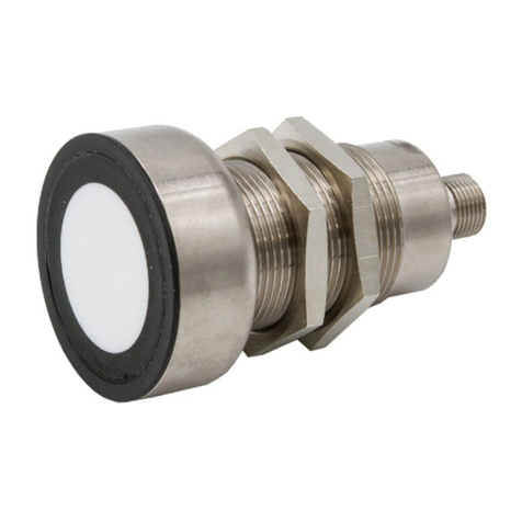
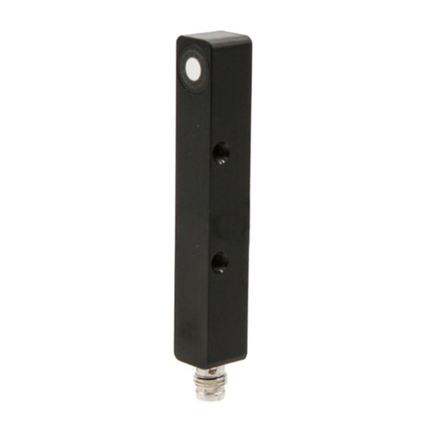
  9. ipf electronic UT129023 User manual

ipf electronic UT129023 User manual

MANUAL • Subject to alteration! Stand: October 2021
ipf electronic gmbh
│
Rosmarter Allee 14 • 58762 Altena • Germany
│
Tel +49 2351 9365-0 • info@ipf-electronic.com •www.ipf-electronic.com 1
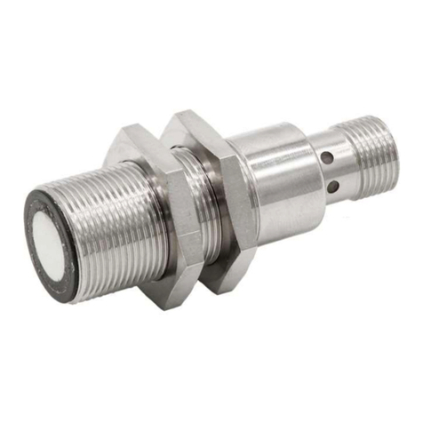
UT129023
Ultrasonic sensors
Diffuse-reflection sensors
IMeasuring range adjustable via teach-in
IAnalog output
IM12-connector
TECHNICAL DATA
Scanning range
40 … 400mm
Operating voltage U
B
18 … 30V DC
Analog output
0 … 10V, 4 … 20mA switchable, not reverse polarity
protected
Load resistance (4 … 20mA)
< 400Ω
Load resistance (0 … 10V)
> 10kΩ
Switching output (adjustable via IO-Link)
Push-Pull, no/nc switchable
Output current (max. load)
150mA
Short-circuit proof +
Reverse polarity protected
+
Voltage drop
2.0V DC
Switching frequency
10Hz
Current consumption (without load
40mA
Standard measuring plate
200 x 200mm
Resolution
1.0mm
Repeatability
1.5mm
Linearity error
0.4%
Mounting distance (sensor to sensor)
200mm
Setting
Teach-In
Carrier frequency
300kHz
Protection class
III
Insulation dielectric strength
500V
Protection class (EN 60529)
IP 67
Material (housing)
Brass nickel plated
Temperature (operation)
-25 … +70°C
Temperature drift
0.2%/K (uncompensated)
Connection
M12-connector 4-pole
Connection accessories
e.g. VK200325
Connection Dimensional drawing
IO-Link-Interface
4 … 20mA / 0 … 10V switchable
Sound outlet
Ultrasonic transducer
MANUAL • Subject to alteration! Stand: October 2021
ipf electronic gmbh
│
Rosmarter Allee 14 • 58762 Altena • Germany
│
Tel +49 2351 9365-0 • info@ipf-electronic.com •www.ipf-electronic.com 2
Approved use
The ultrasonic diffuse-reflection sensor are used as part of a higher-level overall system for the contactless detection of
objects.
Function
The ultrasonic diffuse-reflection sensors work on the principle of time-of-flight measurement. The device transmits a pulse
train, which is then reflected by an object. The device detects the reflected wave and measures the time that has elapsed
between the transmission and reception processes. This time is used to determine the distance between the sensor and
the object. If the results correspond to the specified values, the analog output outputs a value proportional to the distance
and the switching output is set accordingly.
Mounting
The sensor may be mounted in any position. Make sure that it is mounted in a vibration-free and vibration-damping manner.
Also protect the device against mechanical loads such as shocks or impacts.
It is imperative that the transducer surface as well as the area of the detection lobe are kept free. Make sure that there are
no interfering objects between the sensor and the target object inside the lobe. Otherwise, it is possible that the interfering
object will cause false switching. Also avoid positioning two or more ultrasonic sensors opposite each other.
Temperature
The speed of sound in air depends on the temperature. Operation outside the specified ambient temperature is not
allowed. A temperature compensation can be switched on via IO-Link.
When temperature compensation is activated, the sensor requires about 15 minutes of warm-up time after a cold start;
only then are the measured values reproducible.
Transmission angle of the object in diffuse mode
Objects with a smooth surface are scanned reliably up to an angle
of inclination of approx. 10°. The maximum permissible angle of
inclination increases for objects with rough or highly structured
(grained) surfaces.
Blind range in touch mode
The range of 0 … 40mm in front of the sensor corresponds to the ultrasonic
typical blind range.
Distance measurements are not possible in the blind range!
The maximum scanning distance 400 mm.
Detection beams
Plate 200 x 200mm
- - - - - - Round bar Ø 10mm
MANUAL • Subject to alteration! Stand: October 2021
ipf electronic gmbh
│
Rosmarter Allee 14 • 58762 Altena • Germany
│
Tel +49 2351 9365-0 • info@ipf-electronic.com •www.ipf-electronic.com 3
Cleaning
For cleaning a soft cloth moistened with soapy water is recommended.
Commissioning and setting
The measuring range is taught-in and the analog output is switched over by connecting the black wire (PIN 4) to the
operating voltage (PIN1).
The teach process is aborted after 20 seconds (Time Out function)
Make sure that the object to be detected is always within the scanning range limits (40 … 400mm). The distance between
value 1 and value 2 must be at least 100mm.
1. Teach-in of the measuring range
1. Position the object at the point where the analog value should be 4mA or 0V.
2. Connect the black wire to the operating voltage for between 0.1 and 2 seconds. The LED is flashing with approx.
1Hz.
3. Position the object at the point where the analog value should be 20mA or 10V.
4. Connect the black wire to the operating voltage for between 0.1 and 2 seconds.
5. The analog output now operates within the defined measuring limits.
2. Wechseln der Ausgangsfunktion
1. Verbinden Sie die schwarze Ader länger als 6 Sekunden lang mit der Betriebsspannung.
2. Die physikalische Größe des Analogausgang wird gewechselt (statt Stromausgang 4 … 20mA
Spannungsausgang 0 … 10V bzw. umgekehrt).
Hinweis: Beachten Sie, dass für den Betrieb als Spannungsausgang ein wesentlich größerer Lastwiderstand
erforderlich ist (siehe technische Daten). Es wird daher empfohlen, vor jedem Wechsel der
Ausgangsfunktion den Analogausgang abzuklemmen, um Geräteschäden zu vermeiden.
3. LED display after each teach process
If the status LED is flashing twice, the teach process was successful and the sensor is working with the new values.
If the status LED is flashing four times, the teach process has been aborted or the time window of 20 seconds has
been exceeded. The sensor operates with maximum measuring range.
On the following page the descriptions are shown again graphically.
The following additional settings can be made using the IO-Link interface:
Measuring ranges < 100mm
Function of the black wire (PIN 4): Teach-in of the analog output
Switching output (push-pull, PNP or NPN)
Synchronization (see "master-slave function" on page 4)
Multiplex (see "master-slave function" on page 4)
If "switching output" is activated, the switching mode, switching function and
hysteresis can also be set
Analog output: 0 ... 20mA, 4 ... 20mA, 0 ... 10V, disable
Teach switching points (the state of the switching output is always output via IO-Link)
Switch-on and switch-off delay for switching output
Restore factory settings
MANUAL • Subject to alteration! Stand: October 2021
ipf electronic gmbh
│
Rosmarter Allee 14 • 58762 Altena • Germany
│
Tel +49 2351 9365-0 • info@ipf-electronic.com •www.ipf-electronic.com 4
1. Teach-in of the measuring range
2. Changing the output function
(4 ... 20mA - 0 ... 10V)
3. LED display after each teach
process
Master-/slave function
With the help of this function, up to 10 sensors of the same type can be operated in parallel.
To do this, configure the devices accordingly via IO-Link. Define one sensor as the master and all
others as slaves. The master must be assigned the highest number in the network.
Then connect the black wires (PIN 4) with each other (see connection diagram).
The following operating modes can be selected:
1. Synchronous operation: The transmission pulse of all sensors occurs simultaneously with
synchronized evaluation. Select this function for monitoring large
areas.
2. Multiplex operation: The transmission pulses of the sensors are time-delayed in a defined
sequence. The devices can thus no longer influence each other,
smaller distances between them are possible.
Note: Resetting to the factory setting is only possible via IO-Link.
SAFETY INSTRUCTIONS:
Before commissioning, please make sure that all safety instructions listed in the product documentation, if applicable,
have been observed!
In case of direct impact on personal safety, the use of these products is prohibited.

Other ipf electronic Accessories manuals

ipf electronic ON330571 User manual

ipf electronic

ipf electronic ON330571 User manual

ipf electronic ON430571 User manual

ipf electronic

ipf electronic ON430571 User manual

ipf electronic OT05E287 User manual

ipf electronic

ipf electronic OT05E287 User manual

ipf electronic opti-check OC5396 Series User manual

ipf electronic

ipf electronic opti-check OC5396 Series User manual

ipf electronic OT059176 User manual

ipf electronic

ipf electronic OT059176 User manual

ipf electronic UT990934 User manual

ipf electronic

ipf electronic UT990934 User manual

ipf electronic OT330571 User manual

ipf electronic

ipf electronic OT330571 User manual

ipf electronic UT189023 User manual

ipf electronic

ipf electronic UT189023 User manual

ipf electronic PT65 Series User manual

ipf electronic

ipf electronic PT65 Series User manual

ipf electronic OTR49174 User manual

ipf electronic

ipf electronic OTR49174 User manual

ipf electronic UT30C310 User manual

ipf electronic

ipf electronic UT30C310 User manual

ipf electronic UT300025 User manual

ipf electronic

ipf electronic UT300025 User manual

ipf electronic OR150400 User manual

ipf electronic

ipf electronic OR150400 User manual

ipf electronic DW35312 Series User manual

ipf electronic

ipf electronic DW35312 Series User manual

ipf electronic UT139073 User manual

ipf electronic

ipf electronic UT139073 User manual

ipf electronic PRQ80376 User manual

ipf electronic

ipf electronic PRQ80376 User manual

ipf electronic PT230020 User manual

ipf electronic

ipf electronic PT230020 User manual

ipf electronic OTR49170 User manual

ipf electronic

ipf electronic OTR49170 User manual

ipf electronic ON430570 User manual

ipf electronic

ipf electronic ON430570 User manual

ipf electronic OT450521 User manual

ipf electronic

ipf electronic OT450521 User manual

ipf electronic UT139570 User manual

ipf electronic

ipf electronic UT139570 User manual

ipf electronic UT360321 User manual

ipf electronic

ipf electronic UT360321 User manual

ipf electronic DW34312 Series User manual

ipf electronic

ipf electronic DW34312 Series User manual

ipf electronic UT189020 User manual

ipf electronic

ipf electronic UT189020 User manual

Popular Accessories manuals by other brands

StarTech.com ST128HD20 quick start guide

StarTech.com

StarTech.com ST128HD20 quick start guide

KMC Controls THE-1105 installation guide

KMC Controls

KMC Controls THE-1105 installation guide

MICRO-EPSILON ILD1700 user manual

MICRO-EPSILON

MICRO-EPSILON ILD1700 user manual

Panasonic KX-HNS104FX installation guide

Panasonic

Panasonic KX-HNS104FX installation guide

SENSTAR IntelliFIBER Product guide

SENSTAR

SENSTAR IntelliFIBER Product guide

Bitzer OW941B operating instructions

Bitzer

Bitzer OW941B operating instructions

Honeywell RCW110 installation instructions

Honeywell

Honeywell RCW110 installation instructions

PNY PowerPack 6600 user manual

PNY

PNY PowerPack 6600 user manual

Celestron 94182 quick start guide

Celestron

Celestron 94182 quick start guide

Advaning S series How to replace

Advaning

Advaning S series How to replace

Shademaker Rope and Pole installation instructions

Shademaker

Shademaker Rope and Pole installation instructions

Teledyne TIENet 310 Ex Installation and operation guide

Teledyne

Teledyne TIENet 310 Ex Installation and operation guide

Bühler technologies ENK 300-15-4-0.75kW-50Hz Installation and operation instruction

Bühler technologies

Bühler technologies ENK 300-15-4-0.75kW-50Hz Installation and operation instruction

My Child On Board instruction manual

My Child

My Child On Board instruction manual

Svan SVR082C operating instructions

Svan

Svan SVR082C operating instructions

Spralla LLAMA manual

Spralla

Spralla LLAMA manual

Novital Covatutto 108 User Instruction Poster

Novital

Novital Covatutto 108 User Instruction Poster

Tributaries PWRI-X Installation & operation guide

Tributaries

Tributaries PWRI-X Installation & operation guide

manuals.online logo
manuals.online logoBrands
  • About & Mission
  • Contact us
  • Privacy Policy
  • Terms and Conditions

Copyright 2025 Manuals.Online. All Rights Reserved.