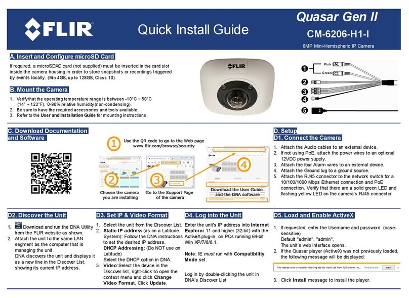
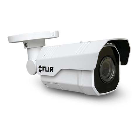
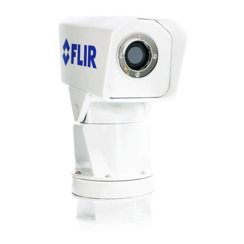
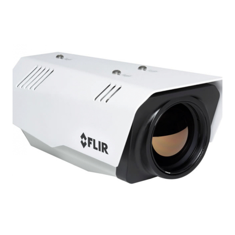
FLIR FC-Series S User manual

Installation
Manual
FC-Series
FC-Series S
FC-Series R

427-0073-12-12 Version 120 May 2015 ii
© 2015 FLIR Systems, Inc. All rights reserved worldwide. No arts of this manual, in whole or in art, may be
co ied, hotoco ied, translated, or transmitted to any electronic medium or machine readable form without the
rior written ermission of FLIR Systems, Inc.
Names and marks a earing on the roducts herein are either registered trademarks or trademarks of FLIR
Systems, Inc. and/or its subsidiaries. All other trademarks, trade names, or com any names referenced herein are
used for identification only and are the ro erty of their res ective owners.
This roduct is rotected by atents, design atents, atents ending, or design atents ending.
The contents of this document are subject to change.
FLIR Systems, Inc
70 Castilian Drive
Goleta, CA 93117
Phone: 888.747.FLIR (888.747.3547)
International: +1.805.964.9797
htt ://www.flir.com
Important Instructions and Notices to the User:
Modification of this device without the ex ress authorization of FLIR Commercial Systems, Inc. may void the user’s
authority under FCC rules to o erate this device.
Note 1: This equi ment has been tested and found to com ly with the limits for a Class B digital device, ursuant to
Part 15 of the FCC rules. These limits are designed to rovide reasonable rotection against harmful interference
in a residential installation. This equi ment generates, uses, and can radiate radio frequency energy and, if not
installed and used in accordance with the instructions, may cause harmful interference to radio communications.
However, there is no guarantee that the interference will not occur in a articular installation. If this equi ment does
cause harmful interference to radio or television rece tion, which can be determined by turning the equi ment off
and on, the user is encouraged to try to correct the interference by one or more of the following measures:
• Reorient or relocate the receiving antenna;
• Increase the se aration between the equi ment and receiver;
• Connect the equi ment into an outlet on a circuit different from that of the receiver; and/or
• Consult the dealer or an ex erienced radio/television technician for hel .
Note 2: This equi ment was tested for com liance with the FCC limits for a Class B digital device using a shielded
cable for connecting the equi ment to an analog video out ut to a monitor and using a shielded USB cable for
connecting the equi ment to a ersonal com uter. When making such connections, shielded cables must be used
with this equi ment.
Industry Canada Notice:
This Class B digital a aratus com lies with Canadian ICES-003.
Avis d’Industrie Canada:
Cet a areil numérique de la classe B est conforme à la norme NMB-003 du Canada.
Proper Disposal of Electrical and Electronic Equipment (EEE)
The Euro ean Union (EU) has enacted Waste Electrical and Electronic Equi ment Directive 2002/96/EC
(WEEE), which aims to revent EEE waste from arising; to encourage reuse, recycling, and recovery of EEE
waste; and to romote environmental res onsibility.
In accordance with these regulations, all EEE roducts labeled with the “crossed out wheeled bin” either on the
roduct itself or in the roduct literature must not be dis osed of in regular rubbish bins, mixed with regular
household or other commercial waste, or by other regular munici al waste collection means. Instead, and in
order to revent ossible harm to the environment or human health, all EEE roducts (including any cables that
came with the roduct) should be res onsibly discarded or recycled.
To identify a res onsible dis osal method nearby, lease contact the local waste collection or recycling service, the original lace
of urchase or roduct su lier, or the res onsible government authority in the area. Business users should contact their su lier
or refer to their urchase contract.
Document History
Version Date Comment
100 A ril 2014 Initial Release
110 June 2014 Minor corrections
120 May 2015 Added descri tion of Analytics setu , descri tion of IDR, other minor corrections
427-0073-12-12 Version 120 May 2015 iii
Table of Contents
Table of Contents
Camera Installation
1.1 Warnings and Cautions ............................................................................................1-1
1.2 References ............................................................................................................... 1-1
1.3 Installation Overview ................................................................................................. 1-2
1.3.1 Camera Connection O tions ............................................................................ 1-2
General Pur ose In ut/Out ut (GPIO) ............................................................. 1-2
PoE+ Power Su lies ...................................................................................... 1-2
1.3.2 Camera Accessories ........................................................................................ 1-3
1.3.3 Su lied Com onents ..................................................................................... 1-3
1.3.4 Required Su lies ...........................................................................................1-3
1.4 Location Considerations ...........................................................................................1-3
1.4.1 Camera Mounting for Rear Cable Access ........................................................1-4
1.4.2 Camera Mounting with Concealed Cable Wall Mount ...................................... 1-5
1.4.3 Sunshield ......................................................................................................... 1-6
1.5 Removing the Cover ................................................................................................. 1-6
1.6 Camera Connections ................................................................................................ 1-7
1.6.1 Prior to Cutting/Drilling Holes ........................................................................... 1-7
1.6.2 Configuring the Lens Heater Jum er ...............................................................1-8
1.6.3 Bench Testing ..................................................................................................1-8
1.6.4 Analog Video Connections ............................................................................... 1-8
1.6.5 Connecting Power ...........................................................................................1-9
1.6.6 Ethernet ...........................................................................................................1-9
1.6.7 GPIO Connections .........................................................................................1-10
1.6.8 Camera Grounding ........................................................................................ 1-11
1.7 Rear Access Cable Gland Sealing .......................................................................... 1-11
1.8 Concealed Cable Mount Accessory ........................................................................ 1-12
1.9 Camera s ecifications ............................................................................................1-15
Basic Operation and Configuration
2.1 IP Camera, ONVIF Profile S Com liant .....................................................................2-1
2.1.1 Server Configuration ........................................................................................ 2-1
2.2 Basic Test and Configuration Ste s .......................................................................... 2-2
2.3 Camera Bench Test .................................................................................................. 2-2
2.3.1 Testing IP Communications ............................................................................. 2-2
2.3.2 Log in to the Camera Web Page ...................................................................... 2-3
2.3.3 Live Video Page ............................................................................................... 2-4
Tem erature—FC-Series R camera only ........................................................ 2-5
Camera Control and Status ............................................................................. 2-5
Web Control Panel .......................................................................................... 2-5
2.3.4 Using FSM .......................................................................................................2-7
2.3.5 Running FSM ................................................................................................... 2-8
2.4 Basic Camera Configuration ................................................................................... 2-10

427-0073-12-12 Version 120 May 2015 iv
Table of Contents
2.4.1 Setu Menu ................................................................................................... 2-10
2.4.2 Server Menu .................................................................................................. 2-10
Services Menu ............................................................................................... 2-12
2.5 Thermal Imaging Overview .....................................................................................2-16
2.6 Troubleshooting Ti s .............................................................................................. 2-18
2.7 Setting the IP address on a Windows PC ................................................................2-23
Advanced Configuration
3.1 Setu Menu .............................................................................................................. 3-1
3.1.1 Thermal Image Setu ....................................................................................... 3-2
IR age ............................................................................................................ 3-2
3.1.2 Video Analytics Setu ...................................................................................... 3-4
Analytics age ................................................................................................. 3-4
3.1.3 Setting Analytics Pro erties .............................................................................3-7
3.1.4 Tem erature Monitoring Setu (FC-Series R camera only) ........................... 3-10
Radiometry Page ...........................................................................................3-10
3.2 Maintenance Menu ................................................................................................. 3-14
3.2.1 Sensor Menu ................................................................................................. 3-14
Communications Menu ..................................................................................3-14
Devices Menu ................................................................................................ 3-16
Modules Menu ............................................................................................... 3-17
3.2.2 Files Menu ..................................................................................................... 3-26
3.2.3 Product Info Menu .......................................................................................... 3-28
3.3 Restoring the Factory Settings ................................................................................3-29
Image from a standard camera in low light Image from a thermal camera in the same
conditions

427-0073-12-12 Version 120 May 2015 1-1
1 Camera Installation
This manual describes the installation and initial configuration of the FC-Series IP thermal cameras,
which includes the FC-Series S and FC-Series R camera models. These camera models are similar in
design and the hysical mounting and installation of both models is the same. The FC-Series R
cameras have all the features of the FC-Series S lus an additional Radiometry feature that rovides
the ability to issue alarms based on tem erature. If hel is needed during the installation rocess,
contact the local FLIR service re resentative or, call 888-747-3547 inside the US.
All installers and integrators are encouraged to take advantage of the training offered by FLIR; visit
htt ://www.flir.com/training for more information.
This manual includes the following to ics:
• Installation overview
• Mounting the camera and its com onents
• Connecting the electronics
• Bench testing the camera
• Basic configuration and o eration of the camera
• Camera S ecifications
For safety, and to achieve the highest levels of erformance from the FC-Series camera system, always
follow the warnings and cautions in this manual when handling and o erating the camera.
1 1 Warnings and Cautions
Warning!
Caution!
1 2 References
FLIR Doc # 427-00XX-XX-19S FC-Series S Interface Control Document (ICD), available on the
documentation CD or from the FLIR website, rovides further details regarding mechanical dimensions
and mounting for the FC-Series camera.
FLIR Doc # 427-0030-00-28 Nexus IP Camera Configuration Guide, rovides more information on
setting or changing camera arameters.
These documents are rovided for reference only.
If mounting the FC-Series camera on a ole, tower or any elevated location, use industry standard
safe ractices to avoid injuries.
Exce t as described in this manual, do not o en the FC-Series camera for any reason. Damage to
the camera can occur as the result of careless handling or electrostatic discharge (ESD). Always
handle the camera with care to avoid damage to electrostatic-sensitive com onents.
Prior to making any connections, ensure the ower su ly or circuit breaker is switched off.
Be careful not to leave finger rints on the FC-Series camera’s infrared o tics.
O erating the camera outside of the s ecified in ut voltage range or the s ecified o erating
tem erature range can cause ermanent damage.

427-0073-12-12 Version 120 May 2015 1-2
1Camera Installation
1 3 Installation Overview
The FC-Series camera is an infrared thermal imaging camera intended for outdoor security
a lications, and can be installed in a fixed location or on a an/tilt mechanism.The FC-Series
camera is intended to be mounted on a medium-duty fixed edestal mount or wall mount commonly
used in the security industry. The camera mount must su ort u to 5 lbs (2.3 kg).
Cables may exit from the back of the camera housing through the
su lied cable gland or from the bottom of the camera housing when
using the concealed cable wall mount (sold se arately). A cable gland
lug is su lied for the rear of the camera housing when cables are
routed using the concealed cable wall mount.
1 3 1 Camera Connection Options
The FC-Series camera can be installed with an analog or digital (IP) video out ut (or both). Analog
video will require a connection to a video monitor or an analog video matrix switch. The camera can
be owered using Power over Ethernet Plus (PoE+) or with a conventional 24 V (ac or dc) ower
su ly. For a PoE+ connection, an accessory PoE+ ower su ly (PN 4132391, also called a PoE+
injector) is available if the camera is not connected to a PoE+ switch. The maximum Ethernet cable
run is 100 meters including the PoE+ ower su ly. In installations using PoE+ ower and IP video,
only a single Ethernet cable from the camera is required.
In installations using analog video and conventional ower (24 Vac is commonly used in many
installations), an RG59U coaxial cable and a three-conductor ower cable are installed. It is
recommended an Ethernet cable should also be installed for camera configuration, o eration and
troubleshooting. The FC-Series camera does not su ort serial communications.
General Purpose Input/Output (GPIO)
The camera can receive a single “contact closure” in ut signal and can rovide a single “contact
closure” out ut signal. Refer to GPIO Connections, g. 1-10.
PoE+ Power Supplies
With PoE+, camera ower is delivered to the camera via the normal Ethernet cable via the camera’s
standard RJ-45 Ethernet connector. The FC-Series camera is a Powered Device com liant with the
IEEE 802.3at-2009 standard, known as PoE+ or PoE Plus. The FC-Series camera is also backward
com atible with the older IEEE 802.3af-2003 standard.
When connected to Power Sourcing Equi ment com liant with the earlier, lower ower IEEE 802.3af-
2003 standard, the limited ower available to the FC-Series camera will revent the formation of frost
and ice. However, the limited ower available from 802.3af-2003 will not fully achieve the camera’s
stated s ecification for de-icing from cold start when the external environment tem erature is < 0 °C.
In all other ways the camera will o erate normally with Ethernet Powered Sourcing Equi ment
com liant to either IEEE PoE standard.

427-0073-12-12 Version 120 May 2015 1-3
1Camera Installation
1 3 2 Camera Accessories
The following accessories are available for urchase from FLIR Systems, Inc.
• PoE+ ower su ly (PN 4132391) - For owering a single FC-Series camera using PoE+. In
addition to PoE+ ower and communications, the ower su ly rovides surge rotection. It
com lies with IEEE 802.3at and is backward com atible with the IEEE802.3af standard.
• Concealed Cable Wall Mount (PN 4129742) - Includes camera mount gasket and hex wrench for
adjusting the ball joint controlling the camera’s view angle.
The FC-Series camera is attached to the mounting arm using the four M5 threaded bottom
mounting holes. A cable gland lug is su lied with the camera for the rear of the camera housing
when cables are routed using the concealed cable accessory. Refer to Camera Mounting with
Concealed Cable Wall Mount, g. 1-5 for installation instructions.
• Pole Mount Ada ter Kit - (PN 4132982) - Ada ter kit that allows the Concealed Cable Wall Mount
to be mounted to a ole (75 mm [3 in] min to 180 mm [7 in]; larger ole diameter requires use of
customer su lied band clam s)
1 3 3 Supplied Components
The FC-Series camera ackage includes these standard com onents:
• Fixed Camera Unit with sunshield and installed cable gland
• Cable gland lug and gland inserts for sealing camera housing
• Power terminal block lug
• Accessory terminal block lug
• Tools: 3 mm hex wrench (T-Handle), small blade screwdriver
• FC-Series Camera Documentation Package
1 3 4 Required Supplies
The installer will need to su ly the following items as required (s ecific to the installation).
• Power cable if used for system ower, 3-conductor, shielded, gauge determined by cable length
and su ly voltage
• PoE+ ower su ly or PoE+ switch if used for system ower
• Cat5e Ethernet cable for digital video and/or PoE+ for system ower
• Coaxial RG59U cables (BNC connector at the camera end) for analog video
• Camera grounding stra , camera mount, miscellaneous electrical hardware, connectors, and
tools
Be sure to use cables that fit in the cable gland holes, as described below. Refer to Rear Access
Cable Gland Sealing, g. 1-11 for more information.
1 4 Location Considerations
The camera will require connections for ower and video. Ensure that cable distances do not exceed
the s ecifications and that cables adhere to all local and industry standards, codes, and best
ractices. The FC-Series camera must be mounted u right, either on to of the mounting surface. or
underneath an overhanging mounting surface such as eaves or an awning. The unit should not be
mounted u side down.
Concealed Cable
Wall Mount

427-0073-12-12 Version 120 May 2015 1-4
1Camera Installation
1 4 1 Camera Mounting for Rear Cable Access
The FC-Series camera can be secured to the mount with two in-line 1/4-20 threaded fasteners on the
to or bottom of the camera. Alternatively the camera can be mounted with four M5 x 0.8 threaded
fasteners to the bottom of the camera. Use Loctite 222 low strength threadlocker for the to mount
fasteners (can be used with the bottom mount fasteners also). Refer to the FC-Series ICD for
additional information.
If using two 1/4-20 fasteners in the center of base, the maximum de th of the fastener should not
exceed 12.5 mm (0.5 in). If using four M5 x 0.8 fasteners, the maximum de th of the fastener should
not exceed 10.0 mm (0.4 in).
If using two 1/4-20 fasteners in the center of to , the maximum de th of the fastener should not
exceed 12.5 mm (0.5 in). If the camera is mounted using the to of the camera, the sunshield must be
removed.
Figure 1-1: FC-Series Camera Bottom Mounting Holes
Figure 1-2: Top Side Mounting Holes

427-0073-12-12 Version 120 May 2015 1-5
1Camera Installation
As the diagram below indicates, be sure to allow adequate s ace for cable egress behind the gland.
This requirement may vary, de ending on the installation. Maintain the bend radius er the
recommendation of the cable manufacturer. The ty ical cable bend radius is 50-75mm (2-3 in).
1 4 2 Camera Mounting with Concealed Cable Wall Mount
The FC-Series camera can be secured to the o tional Concealed Cable Wall Mount with four M5 x
0.8 threaded fasteners to the bottom of the camera. Use Loctite 222 low strength threadlocker for the
mount fasteners. Refer to Concealed Cable Mount Accessory, g. 1-12 for additional information.
Figure 1-3: Rear Cable Bend Radius
Figure 1-4: FC-Series Installed with Concealed Cable Wall Mount and
Pole Adapter kit

427-0073-12-12 Version 120 May 2015 1-6
1Camera Installation
1 4 3 Sunshield
The camera includes a sunshield which should be used for any installation where the camera is
ex osed to direct sunlight or reci itation, If the camera is mounted with the to mounting holes, the
sunshield is not used. De ending on the needs of the installation, the sunshield can be ositioned in
the neutral (middle) osition, or slightly forward or rearward.To change the osition of the sunshield,
tem orarily loosen the three 3 mm hex screws on to , slide the sunshield forward or backward, and
re-tighten the screws.
1 5 Removing the Cover
In order to access the electrical connections
and install the cables, it is necessary to
tem orarily remove the to cover of the
camera housing. The to cover of the
camera is held in lace with four 3 mm hex
screws. The screws are accessible through
slots in the sunshield, so the sunshield does
not need to be removed from the to cover.
Use a 3 mm hex key to loosen the four
ca tive screws, ex osing the connections
inside the camera enclosure. There is a
grounding wire connected inside the case to
the to cover, as shown. If it (or any of the
grounding wires) is tem orarily
disconnected during the installation, it must
be reconnected to ensure ro er grounding
of the camera.
Caution!
Re lace the cover and tighten the four 3 mm hex screws to 1.8 n-m (16.0 in-lbs).
When re lacing the cover, ensure that the ground wire between the cover and the camera body is
com letely inside the o-ring groove. If the wire is inched between the cover and body the camera
is not sealed against water ingress and can be damaged.
Figure 1-5: Sunshield Mounting
Cover mounting screws (x4)
Sunshield mounting screws
Figure 1-6: Cover Removed (Sunshield attached)
Cover mounting
screws (x4)

427-0073-12-12 Version 120 May 2015 1-7
1Camera Installation
1 6 Camera Connections
Refer to Table 1-1 for a descri tion of these camera connections.
1 6 1 Prior to Cutting/Drilling Holes
When selecting a mounting location for the FC-Series camera, consider cable lengths and cable
routing. Ensure the cables are long enough, given the ro osed mounting locations and cable routing
requirements, and route the cables before installing the com onents.
Use cables that have sufficient dimensions to ensure safety (for ower cables) and adequate signal
strength (for video and communications).
Table 1-1: FC-Series Camera Connections
Connection Purpose
1 3- in Jum er Su lemental lens heater on/off
2 RCA Analog video test oint
3 BNC Analog video
4 3- in Terminal ac/dc ower
5 Ethernet PoE+ ower, communications, IP video stream
6 6- in terminal J8 General ur ose I/O
7 Accessory in uts Reserved for future use
Figure 1-7: Camera Connections

427-0073-12-12 Version 120 May 2015 1-8
1Camera Installation
1 6 2 Configuring the Lens Heater Jumper
The su lemental lens heater is intended to rovide lens
de-icing in the rare combination of:
• A ower interru tion which disables the camera for an
extended eriod, and
• Freezing rain which fully covers the lens and obstructs
the image.
FLIR recommends that the su lemental lens heater be
enabled only when the installation environment is such that
this combination of conditions is common.
The FC-Series camera is shi ed from the factory with the su lemental lens heater OFF (jum er
ins 2 and 3). To enable the Su lemental Lens Heater, move the heater jum er to ON (jum er ins 1
and 2). Pro er o eration of the Su lemental Lens Heater requires that the camera be owered by 24
Vac, >16Vdc or POE+.
It is im ortant to note that the su lemental lens heater is not required for o eration in all cold
tem eratures. The system o erates to s ecification and roduces highest quality images without the
Su lemental Lens Heater. Contact FLIR Technical Su ort for additional information (888-747-3547
inside the US).
1 6 3 Bench Testing
Note
Connect the ower, Ethernet, and video, and confirm that the video can be dis layed on a monitor
when the ower is turned on. For configuration and basic setu information using the onboard web
server, refer to Camera Bench Test, g. 2-2 for s ecific details.
1 6 4 Analog Video Connections
The rimary analog video connection of the camera is a BNC connector. Alternatively, the camera
also rovides an RCA analog video connector. Only one or the other connection should be used on a
ermanent basis to ensure adequate video quality. The RCA connection allows the installer to
tem orarily monitor the video out ut, without disconnecting the rimary connection.
The video cable used should be rated as RG-59/U or better to ensure a quality video signal.
Note
If the camera is to be mounted on a ole or tower or other hard-to-reach location, it may be a good
idea to connect and o erate the camera as a bench test at ground level rior to mounting the
camera in its final location.
Insert the cables through the cable glands on the enclosure before terminating and connecting them.
In general, terminated connectors will not fit through the cable gland. If a terminated cable is required,
it is ossible to make a clean and singular cut in the gland seal to install the cable into the gland seal.
Figure 1-8: Lens Heater Jumper Setup
Pin 1
Pin 2
Pin 3

427-0073-12-12 Version 120 May 2015 1-9
1Camera Installation
1 6 5 Connecting Power
The camera can be owered with a conventional ac or dc ower
su ly, rather than PoE+. Prior to making any connections,
ensure the ower su ly or circuit breaker is switched off.
The ower cable su lied by the installer must use wires that are sufficient size gauge for the su ly
voltage and length of the cable run, to ensure adequate current carrying ca acity (18 AWG
recommended for most installations). Always follow local building/safety codes.
Note
The ower connector lug may be removed for cable installation. After the lug is reattached to the
board, re-tighten the screw terminals.
The camera itself does not have an on/off switch. Generally the FC-Series camera may be connected
to a circuit breaker and the circuit breaker will be used to a ly or remove ower to the camera. If
ower is su lied to it, the camera will be owered on and o erating.
1 6 6 Ethernet
Connect a shielded cat5e/6 Ethernet cable to the
RJ-45 jack. If using PoE+ to su ly ower to the
camera, connect the other end of the Ethernet to a
PoE+ switch or PoE+ injector. Otherwise connect
the Ethernet to a network switch.
Table 1-2: Power Connections
1 Chassis
2 VAC/VDC -
3 VAC/VDC +
The terminal connector for ower connections will acce t 16 AWG to 24 AWG wire size.
Figure 1-9: Power Connector
Figure 1-10: Power Cable (3 conductor)
Remove outer cover
Strip wires
Ethernet
GPIO
J8 pin 1
Figure 1-11: GPIO and Ethernet Connectors

427-0073-12-12 Version 120 May 2015 1-10
1Camera Installation
1 6 7 GPIO Connections
Input Signal—The camera can receive an external
in ut signal on accessory connector J8 ins 4 and 5
when these ins are connected by an external
switch closure. Pin 5 is connected to the camera’s
internal +5V ower su ly and must not be directly
connected to chassis ground. Pin 4 is connected to
the internal digital ground.
While rotection for static discharge has been
laced on these ins, care should be used in
making connections to the ins to avoid
connections to other voltages or ower sources
outside the camera.
Output Signal—The camera can rovide a contact closure out ut on accessory connector J8 ins 2
and 3 when an external voltage is su lied to these ins. When o en the resistance between ins 2
and 3 is greater than 100 K ohm. When closed the resistance between ins 2 and 3 is less than 200
ohm. The maximum recommended eak voltage between the ins is 6 volts. The maximum
recommended current allowed between the ins is 30 mA (0.03 A).
Note
Table 1-3: GPIO Connections - J8
Pin Connection Notes
1 Chassis ground
2 GPIO Out When the camera sends an out ut signal, an
external voltage on one in is a lied to the
other in.
3 GPIO Out
4 Digital ground When these ins are connected externally,
the camera reads this as an in ut signal.
5 +5V
6 Chassis ground
The terminal lug su lied for GPIO connections uses stranded 26 AWG wire size (1 mm diameter
including insulation) using s ring-cage and ierce contact technology.
Figure 1-13: GPIO and Ethernet Connectors
pin 1
1 Insert wires 2 Snip wire
through plug and close cage

427-0073-12-12 Version 120 May 2015 1-11
1Camera Installation
1 6 8 Camera Grounding
Ensure the camera is ro erly grounded. Failure to
ro erly ground the camera can lead to ermanent
damage to the camera. Ty ical to good grounding
ractices, the camera chassis ground should be
connected to the lowest resistance ath ossible.
The camera has an external ground connection on
the outside back of the camera. FLIR requires a
grounding stra anchored to the grounding lug and
connected to the nearest earth-grounding oint.
If, during installation, any ground connections
inside the camera are disconnected, they should
be reconnected rior to closing the camera.
1 7 Rear Access Cable Gland Sealing
Pro er installation of cable sealing gland and use of a ro riate elastomer inserts is critical to long
term reliability. Cables enter the rear of the camera mount enclosure through a liquid-tight
com ression gland.
Leave the gland nut loosened until all cable installation has been com leted, and ensure the
manufacturer’s recommended cable bend radius is observed within the enclosure. Do not forget to
tighten the cable gland seal nut to ensure a watertight seal and rovide strain relief for cables.
Cable Gland Seal Inserts
The FC-Series camera comes with a single 3/4” NPT cable gland installed in the camera, with a four-
hole gland seal insert. The gland includes a sealing washer and is secured to the camera with a nut
on the inside of the enclosure. The gland insert has one hole for the RG-59/U analog video cable (the
larger hole) and three more for a ower cable, Ethernet cable, and an accessory cable (not used at
this time).
Any of the holes which are not used for cables should be filled with one
of the hole lugs (su lied). Install the cables through the cable gland
so that the cables line u with the connections inside the camera.
Note
To ensure a water tight seal when using the su lied rear cable gland, cable dimensions must be
within the minimum and maximum as described in Table 1-4.
If non-standard cable diameters are used, an a ro riate cable gland and insert should be used to fit
the desired cable and to fit the hole in the enclosure. FLIR Systems, Inc. does not rovide cable gland
inserts other than the insert su lied with the system.
If a re lacement is used, ins ect and install the gland fitting in the back cover with suitable leak seal or
sealant and tighten to ensure water tight fittings. To fit the 1.050 in. (26.7 mm) hole in the enclosure,
the thread size should be 3/4” NPT or M25. The gland should be installed with a sealing washer (for
exam le, Heyco PN 3261 or equivalent) between the gland and the external surface of the enclosure.
Insert the cables through the cable glands on the enclosure before terminating and connecting them.
In general, terminated connectors will not fit through the cable gland. If a terminated cable is required,
it is ossible to make a clean and singular cut in the gland seal to install the cable into the gland seal.
Figure 1-15: Camera Ground Connection
Ground

427-0073-12-12 Version 120 May 2015 1-12
1Camera Installation
1 8 Concealed Cable Mount Accessory
Do not route cables through the bottom of the camera unless the concealed cable wall mount (PN
4129742) is used. The wall mount is s ecifically designed for the camera and allows the o ening to
seal ro erly. When using the concealed cable wall mount, cable dimensions must be within the
minimum and maximum as described in Table 1-5.
Pro er installation of the seal late and anel mount gland seals is critical to long term reliability.
Cables enter the bottom of the camera enclosure through the seal late and anel mount glands. Be
sure to insert each cable through its anel mount gland on the seal late before terminating them
(connectors will not fit through the gland). Ensure the manufacturer’s recommended cable bend
radius is not exceeded within the enclosure.
Prepare the Camera
Ste 1 Use a 3 mm hex key to loosen the four ca tive screws and remove the to cover as
described above.
Table 1-4: Rear Exit Cable Min/Max Dimensions
Cable Minimum Maximum Notes
Power (3 conductor),
Ethernet, Accessory
cables
4.5 mm
[0.178 in]
5.2 mm
[0.205 in]
When using the concealed cable wall mount
(PN 4129742), cables can have a maximum diameter
of 10 mm [0.394 in]
RG 59 Video cable 5.3 mm
[0.209 in]
6.4 mm
[0.245 in]
Table 1-5: Cable Min/Max Dimensions using Concealed Cable Wall Mount (PN 4129742)
Cable Minimum Maximum Notes
Power (3 conductor),
Ethernet, Accessory
cables
4.5 mm
[0.178 in]
10 mm
[0.394 in]
When using the rear exit cable gland, the maximum
diameter is 5.2 mm [0.205 in]
RG 59 Video cable 5.3 mm
[0.209 in]
10 mm
[0.394 in]
Figure 1-16: Cable Routing
Power Cable
Video Cable
Accessory cable
Ethernet
RG 59 coaxial
3 Conductor

427-0073-12-12 Version 120 May 2015 1-13
1Camera Installation
Ste 2 Remove the rear cable gland and re lace it with the cable gland lug. Use the gasket and
nut that were removed with the cable gland.
Ste 3 Use a 3 mm hex key to
loosen the four ca tive
screws and remove the
seal late, o-ring, and
lug.
Ste 4 Install the wall mount (PN
4129742) to the wall and ull the cable(s)
through the mount. Cut a small cross-slit in the
black mount gasket and ush the cable(s)
through the gasket. Pull the cable(s) through
the o ening in the bottom of the camera. A
single Ethernet cable is shown in the images.
Ste 5 Secure the camera to the mount using four M5
x 0.8 threaded fasteners to the bottom of the
camera. Use Loctite 222 low strength thread
locker for the mount fasteners.
Ste 6 As needed, clean the o-ring and the o-ring
groove in the bottom of the camera using isotro y
alcohol and ress the o-ring into its groove.
Ste 7 For each cable, unch hole in the center of a gland
seal from the to using the 3 mm hex key. Insert the
cable from the bottom though the hole.
Ste 8 Place the gland late back into osition and tighten
the four 3 mm ca tive screws using a torque value
of 1.8 n-m (16.0 in-lbs).
Ste 9 Check the length of each cable to ensure an
a ro riate bend radius and terminate the cable.
Figure 1-17: Seal Plate Removed
Panel mount gland seals (x4)
Seal plate
Gland plug
Plug
installed
Figure 1-18: Removed Parts
Figure 1-19: Camera Mount
Mount Gasket
Figure 1-20: Cable through Seal Plate

427-0073-12-12 Version 120 May 2015 1-14
1Camera Installation
Ste 10 Push the cable back through the gland seal so that the seal is extended down not u , as
shown in the illustration below.
Ste 11 Connect the cables as indicated in Figure 1-7 on age 1-7. Ensure that any ground wire
that was removed during installation is reconnected. Re lace the cover and tighten the four
3 mm hex screws to 1.8 n-m (16.0 in-lbs).
Caution!
Ste 12 Using the hex key that is included with the concealed cable mount, loosen the ball joint on
the bottom of the mount, osition the camera as required, and then re-tighten the ball joint.
When re lacing the cover, make sure the ground wire between the cover and the camera body is
com letely inside the o-ring groove. If the wire is inched between the cover and the base, the
camera will not be sealed against water ingress and could be damaged.
Wrong
Correct

427-0073-12-12 Version 120 May 2015 1-15
1Camera Installation
1 9 Camera specifications
Camera Models FC-Series S, FC-Series R
Camera Platform Ty e Fixed
Com osite Video NTSC or PAL
Thermal Camera
Array Format 324x256 (25 µm ixel itch)
336x256, 640x480 (17 µm ixel itch)
Detector Ty e Long-Life, Uncooled VOx Microbolometer
Effective Resolution 76,800
Field Of View (Focal Length) for
available FC-Series S camera lens
configurations.
FC-363 S = 63° × 50° (7.5 mm)
FC-348 S = 48° × 39° (9 mm)
FC-334 S = 34° × 28° (13 mm)
FC-324 S = 24° × 19° (19 mm)
FC-313 S = 13° × 10° (35 mm)
FC-309 S = 9° × 8° (35 mm)
FC-690 S = 90° × 69° (7.5 mm)
FC-669 S = 69° × 56° (9 mm)
FC-645 S = 45° × 37° (13 mm)
FC-632 S = 32° × 26° (19 mm)
FC-618 S = 18° × 14° (35 mm)
Field Of View (Focal Length) for
available FC-Series R camera lens
configurations.
FC-334 R = 34° × 28° (13 mm)
FC-324 R = 24° × 19° (19 mm)
FC-645 R = 45° × 37° (13 mm)
FC-632 R = 32° × 26° (19 mm)
S ectral Range 7.5 to 13.5 μm
Lens Athermalized, focus-free
General
Weight 4.8 lb (2.2 kg) with sun shield
Dimensions (L,W,H) 11.1" x 5.1" x 4.5" with sunshield,
(282 mm x 129 mm x 115 mm)
In ut Voltage - dc 14 - 32 Vdc
In ut Voltage - ac 18 - 27 Vac
In ut Voltage - PoE+ IEEE 802.3af-2003 standard or higher ower,
IEEE 802.3at-2009 standard
Power Consum tion 5 W nominal at 24 Vdc
8 VA nominal at 24 Vac
Peak at 24 Vdc: 21 W with su lemental lens heater
Peak at 24 Vac: 29 VA with su lemental lens heater
Mounting Provisions Two 1/4-20” threaded holes on to and bottom,
1" s acing along center line front to back.
Four M5 threaded holes bottom,
40 mm x 62 mm (1.6 in x 2.4 in) s acing square.
Shi ing weight 6.1 lbs (2.8 kg)

427-0073-12-12 Version 120 May 2015 1-16
1Camera Installation
Shi ing Dimensions 14.375”(L) x 7.375”(W) x 7”(H)
Environmental
IP rating (dust and water ingress) IP66 & IP67
O erating tem erature range -50 °C to 70 °C (-58 °F to 158 °F) continuous
-40 °C to 70 °C (-40 °F to 158 °F) cold start
Storage Tem erature range -55 °C to 85 °C (-67 °F to 185 °F)
Humidity 0-95% relative
Shock IEC 60068-2-27 10 g shock ulse
with a 11ms half-sine rofile
Vibration MIL-STD-810F
A rovals FCC Part15, Sub art B, Class B,
EN 55022 Class B, EN 50130-4,
EN60950
Other manuals for FC-Series S
2
Table of contents
Other FLIR Security Camera manuals

FLIR
FLIR PatrolIR B User manual

FLIR
FLIR Navigator II User manual

FLIR
FLIR FC-Series Assembly instructions

FLIR
FLIR DCV64DL User manual

FLIR
FLIR CB-3102 Manual

FLIR
FLIR MPX C243EW2 Series User manual

FLIR
FLIR Saros User manual

FLIR
FLIR SV87-KIT User manual

FLIR
FLIR N258F5 Series User manual

FLIR
FLIR Lorex LWB3801-W User manual

FLIR
FLIR FX User manual

FLIR
FLIR DBV534TL User manual

FLIR
FLIR DBV54TL User manual

FLIR
FLIR PT series User manual

FLIR
FLIR Digimerge DPV24DLR User manual

FLIR
FLIR MPX ME363 User manual

FLIR
FLIR DPB34TLX User manual

FLIR
FLIR CP-6302-30-R User manual

FLIR
FLIR IP Series User manual

FLIR
FLIR Lorex LNE3322 Series User manual