Flo-tech FT555 Series User manual

FloTech
FT555 Series
Automatic Truck Overfill
System Tester
Optic Systems
Thermistor Systems
Ground Bolt
TIM Module
10784PA REV F
Dixon
Dixon Bayco Division
Cincinnati, Ohio

FloTech FT555 Automatic Truck Overfill System Tester
Page 2 10784PA REV F FT555 Truck Tester
Table of Contents
Table of Contents............................................................................ 2
Introduction..................................................................................... 3
Main Features.................................................................................. 3
FT555 Indicators............................................................................. 5
Unpack Unit and Initial Setup......................................................... 6
Welcome Screen ............................................................................. 7
Power On/Off.................................................................................. 7
Setup Instructions............................................................................ 8
Selecting Test Option.................................................................... 11
Performing Automatic Test Fuction ............................................. 11
Optic Test...................................................................................... 13
Thermistor Test............................................................................. 14
Ground Bolt Test........................................................................... 16
Trailer ID Module Test................................................................. 17
Optic and Thermistor Wet Test..................................................... 19
Accessories ................................................................................... 21
Technical Support Hotline............................................................ 22

FloTech FT555 Automatic Truck Overfill System Tester
Page 22 10784PA REV F FT555 Truck Tester
CAUTION:
The FT555 is not certified as suitable for use in a Class I
Division 1 hazardous location. You should avoid use in
explosive or flammable atmospheres.
Troubleshooting:
a) Should the FT555 fail to start or shut down during use,
check the battery indicator on the welcome screen and or
replace the batteries.
b) Should the FT555 appear to freeze, remove the batteries to
force the unit to power down. Reinstall the batteries and
begin test procedure. By removing the batteries you will
force the FT555 to restart back to the welcome screen.
Technical Support Hotline
(877) 582-3569
Contact the FloTech Technical Support Hotline for help:
Troubleshooting overfill systems.
Verifying defective components
To request an RGA for defective FloTech products under
warranty.
FloTech FT555 Automatic Truck Overfill System Tester
FT555 Truck Tester 10784PA REV F Page 3
Introduction
This Manual describes the features, use, and maintenance of the
FT555 Automatic Truck Overfill System Tester. The FT555 is
compatible with all makes of Optic sensor systems, 2 wire
Thermo-Optic systems, and truck onboard monitor systems
regardless of manufacture as long as they are compatible with API
RP1004: 2003 recommended practice.
Main Features
The FloTech FT555 Automatic Truck Overfill System Tester has
the following features:
-Automatically test all 4 test functions, Optic, Thermistor,
Ground Bolt, and TIM number.
-Test all API 5 wire optic sensor systems and report the
number of functional / wetted sensors*.
-Test 2 wire Thermo–Optic sensors and report the number
of functional / wetted sensors*.
-Monitors up to eight compartments.
-Test Ground Bolts with both forward and reverse continuity
check.
-Read TIM modules and report serial number in display
-Perform “WET TEST” to report when sensors are wetted
using integrated beeper.
-Configure auto test to perform all selected tests at once.
-Configure maximum number of compartments.
-Software can be upgraded to include new tests and future
expanded testing and troubleshooting capability.
* Optic and thermistor tests will only indicate correct number
of functional / wetted sensors for systems without an onboard
monitor.

FloTech FT555 Automatic Truck Overfill System Tester
Page 4 10784PA REV F FT555 Truck Tester
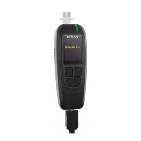
Fig. 1 FT555 Automatic Truck Tester
FloTech FT555 Automatic Truck Overfill System Tester
FT555 Truck Tester 10784PA REV F Page 21
Accessories
Contact Flotech Customer Service (1-800-355-1991) or your
local Flotech distributor for pricing and availability
information on the following accessories.
1. FT556 – USA Test cable package
This cable package is suited for use on systems in the US.
Package Contents:
a. Accessory Adapter
b. Optic sensor test cable
c. Thermistor sensor test cable
d. API Socket extension cable
e. Truck ID Modules test cable
f. Groundbolt test cable
2. FT557 – Non-USA Test cable package
This cable package is suited for use on systems outside the
USA.
Package Contents:
a. Accessory Adapter
b. Optic sensor test cable
c. Thermistor sensor test cable
d. API Socket extension cable
e. J560 Socket extension cable
f. Ground Continuity test cable
g. Groundbolt test cable

FloTech FT555 Automatic Truck Overfill System Tester
Page 20 10784PA REV F FT555 Truck Tester
Step 5) The FT555 will repeatedly test for the presence of any wet
sensors connected to the socket.
Step 6) Dip test a compartment and listen for a number of beeps
corresponding to the compartment number that was dipped. The
display will also indicate the compartment number of the wet
sensor*.
Step 7) Continue testing each compartment.
Step 8) Stop the wet test by pressing any key.
NOTE: IF THE TESTER DOES NOT SEE ANY SENSORS
OR IS NOT CONNECTED, IT WILL DISPLAY THE
ABOVE SCREEN UNTIL IT SEES A SENSOR OR THE
TEST IS STOPPED.
* 1.The wet test function will only indicate correct wet
compartment number for systems without an onboard
monitor.
2. Systems using an onboard monitor will only show sensor 1
wet when any sensor becomes wet.
FloTech FT555 Automatic Truck Overfill System Tester
FT555 Truck Tester 10784PA REV F Page 5
FT555 Indicators
A) LCD SCREEN
The LCD screen is the main display where test selection, test results, and
test instructions are displayed. Screen backlight is enabled using the
ON/OFF button.
B) ON/OFF BUTTON
Press this button to turn the FT555 Automatic Truck Tester on and off.
The unit will automatically turn off after 10 minutes. Press and hold this
button for 2 seconds and the backlight will illuminate.
C) TEST SELECT BUTTON
Press this button to cycle through the available tests.
D) GO BUTTON
Press this button to start the selected test.
E) WET TEST BUTTON
Press this button while in the Optic or Thermistor Test mode and the wet
test feature will begin. Pressing any button will stop the wet test.
F) SETUP BUTTON
Press this button to enter the set up screens.
G) BATTERY DOOR
Twist to open, hold two D cells, positive points towards battery door
(out).
H) ALARM
Audible alarm sounds when FT555 Automatic Tester is in WET TEST
mode and sensor is wetted.
I) API PLUG CONNECTOR
API compatible plug with configurable J-Slot pins for both optic and
thermistor sockets.

FloTech FT555 Automatic Truck Overfill System Tester
Page 6 10784PA REV F FT555 Truck Tester
Unpack Unit and Initial Setup
Step 1) When unpacking the FT555 Automatic Truck Tester you
will find the following:
a) FT555 Automatic Truck Tester
b) Two “D” size batteries
c) Three J-Slot thumb screws
d) This instruction manual
Step 2) Screw in the three J-Slot Screws into the threads marked
“O” for Optic socket compatibility and into the J-Slot threads
market “T” for thermistor socket compatibility.
Step 3) Remove the battery door by turning counter clock wise
until door opens. Insert two “D” size batteries with positive
battery terminal facing out of the opening. Reinstall battery door
by turning clockwise.
DO NOT FORCE BATTERY DOOR OPEN OR CLOSE
Step 4) Press the ON/OFF button once. The FT555 will show the
Initial System Setup screen shown below:
Step 5) Complete the Initial System Setup following the setup
instructions on page 8.
FloTech FT555 Automatic Truck Overfill System Tester
FT555 Truck Tester 10784PA REV F Page 19
Optic and Thermistor Wet Test
NOTE: THE WET TEST FUNCTION IS INTENDED TO BE
USED ON WORKING SYSTEMS. IF THE SYSTEM HAS A
PROBLEM IT MUST BE REPAIRED BEFORE USING WET
TEST.
Step 1) Move the J-Slot thumb screws to the correct holes to match
the type of socket to be connected. Follow the “O” and “T”
markings on the plug body for optic and thermistor style sockets,
respectively.
Step 2) Connect the FT555 Automatic Truck Tester to the trailer
socket.
Step 3) Press the ON/OFF button to turn on the FT555 Automatic
Truck Tester. When “Press Key” screen appears press “TEST
SELECT” button until the “Optic Test” or “Thermistor Test”
screen appears, depending on the socket the tester is connected to.
Step 4) Press “WET TEST” button to begin the wet test.

FloTech FT555 Automatic Truck Overfill System Tester
Page 18 10784PA REV F FT555 Truck Tester
Trailer ID Module Test
The Trailer ID Module will be tested and report the 12 digit serial
number stored inside the ID module. If there is no trailer ID
module or the test fails the screen will show “TIM not found”
Step 1) Move the J-Slot thumb screws to the correct holes to match
the type of socket to be connected. Follow the “O” and “T”
markings on the plug body.
Step 2) Connect the FT555 Automatic Truck Tester to the trailer
socket.
Step 3) Press the ON/OFF button to turn on the FT555 Automatic
Truck Tester. When “Press Key” screen appears press “TEST
SELECT” button five times so the “Trailer ID Module Test”
screen appears.
Step 4) Press the “GO” button to start the test. When the test is
complete the screen will report the 12 digit serial number or show
“TIM not found”.
Step 5) Press the TEST SELECT” button to move on to a new test,
press “GO” to restart the test, or press the “ON/OFF” button to
turn the tester off.
FloTech FT555 Automatic Truck Overfill System Tester
FT555 Truck Tester 10784PA REV F Page 7
Welcome Screen
After completing the Initial System Setup the welcome screen will
be displayed. This screen will be displayed every time the FT555
Automatic Truck Tester is turned on.
The Welcome Screen shows the version software the FT555 is
running and the battery health status in bars. 5 bars represent full
battery capacity. If 2 or less bars are displayed, a warning beep will
sound and a warning message will flash for a few seconds.
Batteries should be changed at your next convenience.
Power On/Off
Press the ON/OFF button once to turn the tester on. Push the
button again to turn the tester off. The tester has a display back
light for dark conditions. After turning on the tester, press and
hold the ON/OFF button for 2 seconds and the back light will turn
on. Press and hold again for 2 seconds and the back light will turn
off.

FloTech FT555 Automatic Truck Overfill System Tester
Page 8 10784PA REV F FT555 Truck Tester
Setup Instructions
At the “Press Key” screen pressing the SETUP key will enter the
setup mode. The first option will be:
MAX OPTIC COMPS = #
Press the GO button to toggle between 6 and 8 maximum number
of compartments. Generally the USA has a maximum of 6
compartments signals per one socket and Canada or European
regions will have a maximum of 8. Once the correct number of
maximum compartments is displayed, press TEST SELECT button
to move to the next SETUP screen.
MAX THERM COMPS = #
Press the GO button to toggle between 6 and 8 maximum number
of compartments. Generally the USA has a maximum of 6
compartments signals per one socket and Canada or European
regions will have a maximum of 8. Once the correct Maximum
Compartments count is showing, press TEST SELECT button to
move to the next SETUP screen.
FloTech FT555 Automatic Truck Overfill System Tester
FT555 Truck Tester 10784PA REV F Page 17
Pin 9/10 Continuity Test
Pins 9 and 10 of the API socket will be tested for continuity and
the result of the test will be shown as PASS or FAIL on screen.
Step 1) Move the J-Slot thumb screws to the correct holes to match
the type of socket to be connected. Follow the “O” and “T”
markings on the plug body.
Step 2) Connect the FT555 Automatic Truck Tester to the trailer
socket.
Step 3) Press the ON/OFF button to turn on the FT555 Automatic
Truck Tester. When “Press Key” screen appears press “TEST
SELECT” button four times so the “Ground Continuity Test”
screen appears.
Step 4) Press the “GO” button to start the test. When the test is
complete the screen will report either “PASS” or “FAIL”.
Step 5) Press the TEST SELECT” button to move on to a new test,
press “GO” to restart the test, or press the “ON/OFF” button to
turn the tester off.

FloTech FT555 Automatic Truck Overfill System Tester
Page 16 10784PA REV F FT555 Truck Tester
Ground Bolt Test
The Ground Bolt will be tested using the forward and reverse test
to confirm proper operation of the diode inside the ground bolt.
The tester will report a Pass/ Fail.
Step 1) Move the J-Slot thumb screws to the correct holes to match
the type of socket to be connected. Follow the “O” and “T”
markings on the plug body.
Step 2) Connect the FT555 Automatic Truck Tester to the trailer
socket.
Step 3) Press the ON/OFF button to turn on the FT555 Automatic
Truck Tester. When “Press Key” screen appears press “TEST
SELECT” button four times so the “Ground Bolt Test” screen
appears.
Step 4) Press the “GO” button to start the test. When the test is
complete the screen will display the PASS / FAIL status.
Step 5) Press the TEST SELECT” button to move on to a new test,
press “GO” to restart the test, or press the “ON/OFF” button to
turn the tester off.
FloTech FT555 Automatic Truck Overfill System Tester
FT555 Truck Tester 10784PA REV F Page 9
AutoTest Optic/Therm
Some regions may not have a need to test optic or thermistor type
systems as none are found in that region. Example, trailers in
California do not have Thermistor sockets so there is no need to
perform the Thermistor test. In this case the Optic test would be
enabled.
This screen will enable or disable the Optic or Thermistor tests
when performing an automatic test of the trailer overfill system.
This configuration is only for the automatic testing mode. All four
tests are available in the manual test selection.
Press the “GO” button to choose between “Enable BOTH”,
“Enable OPTIC” or “Enable THERM” Press the “TEST
SELECT” button to move to the next screen.
Auto Test Ground Bolt- OPTIONAL
Press the “GO” button to ENABLE or DISABLE the ground bolt
test during the automatic testing. PRESS “TEST SELECT” button
to move to the next screen.

FloTech FT555 Automatic Truck Overfill System Tester
Page 10 10784PA REV F FT555 Truck Tester
Auto Test Ground Continuity System- OPTIONAL
1. Press GO to select either Ground Bolt or Continuity. Once
the selection has been made, press TEST SELECT to move
to the next screen. See step 2 for Continuity or step 3 for
Ground Bolt.
2. Continuity
If you selected Continuity, the screen below will be shown,
press GO to Enable or Disable the Auto Test function.
Press TEST SELECT to move to the Automatic Test
Screen, see Performing Automatic Test Function on pg. 11.
3. Ground Bolt
If you selected Ground Bolt, the screen below will be
shown, press GO to Enable or Disable the Auto Test
function. Press TEST SELECT to move to the Automatic
Test screen, see Performing Automatic Test Function on
pg.11.
FloTech FT555 Automatic Truck Overfill System Tester
FT555 Truck Tester 10784PA REV F Page 15
Step 3) Press the ON/OFF button to turn on the FT555 Automatic
Truck Tester. When “Press Key” screen appears press “TEST
SELECT” button three times so the “Thermistor Test” screen
appears.
Step 4) Press the “GO” button to start the test. When the test is
complete the screen will display the PASS / FAIL status and a
wet/dry status for each of the compartments enabled during the
setup. A square under the number indicates a dry sensor or a dash
under the number indicates a wet or missing sensor. If connected to
an Onboard Monitor dashed lines will show and no black bars.
Step 5) Press the “TEST SELECT” button to move on to a new
test, press “GO” to restart the test, or press the “ON/OFF” button
to turn the tester off.

FloTech FT555 Automatic Truck Overfill System Tester
Page 14 10784PA REV F FT555 Truck Tester
Step 5) Press the “TEST SELECT” button to move on to a new
test, press “GO” to restart the test, or press the “ON/OFF” button
to turn the tester off.
Optic pass when connected to sensors is shown above. A black
square will be shown for each dry working sensor.
Optic pass when connected to an onboard monitor will show
dashes for sensor status. Onboard monitors do not have a
diagnostic connection to the rack monitor and do not pass the
number of good sensors through the onboard monitor to the socket.
Thermistor Test
The API Thermistor signal from the trailer mounted sensors or
onboard monitor will be tested and report a Pass/ Fail.
OPERATION NOTE:
This tester is not compatible with the old style analog “green or
silver tipped sensors. These devices require the FT510 tester.
Step 1) Move the J-Slot thumb screws to the correct holes to match
the type of socket to be connected. Follow the “O” and “T”
markings on the plug body.
Step 2) Connect the FT555 Automatic Truck Tester to the trailer
socket.
FloTech FT555 Automatic Truck Overfill System Tester
FT555 Truck Tester 10784PA REV F Page 11
Auto Test Truck ID Module- OPTIONAL
Press the “GO” button to ENABLE or DISABLE the Truck ID
Module test during the automatic testing. PRESS “TEST
SELECT” button to exit the SETUP mode and return you to the
“PRESS KEY TEST SELECT” screen.
Selecting Test Option
When at the “Press Key” screen, each time the TEST SELECT
button is pressed the tester will cycle through each of the five
available testing modes:
AUTOMATIC TEST
OPTIC TEST
THERMISTOR TEST
GROUND BOLT TEST
TRAILER ID MODULE TEST
Performing Automatic Test Function
This test option will automatically test all of the available test
options previously enabled in the setup procedure above, and
report the findings in a PASS / FAIL screen.
Step 1) Press the ON/OFF button to turn on the FT555 Automatic
Truck Tester. When “Press Key” screen appears press “TEST
SELECT” button one time so the “Automatic Test” screen appears.
Step 2) Press the “GO” button to start the test. Follow the prompts
listed in the display screen.

FloTech FT555 Automatic Truck Overfill System Tester
Page 12 10784PA REV F FT555 Truck Tester
Step 3) Move the J slot screws to match the J-Slot configuration of
the optic socket.
Step 4) Connect the tester to the optic socket.
Step 5) Press go button to start the test.
Step 6) Once the optic portion of the test is complete disconnect
the tester from the optic socket.
Step 7) Move the J-Slot Screws to match the configuration of the
Thermistor socket.
Step 9) Connect the tester to the thermistor socket and press the go
button to start the thermistor portion of the test.
The tester will automatically test the ground bolt and TIM module
if these options are enabled in the set up screen.
If the tester encounters a failure during any portion of the
automatic test it will halt and display the failure on the display.
When the test is complete the Screen will display the PASS / FAIL
status of each test performed.
FloTech FT555 Automatic Truck Overfill System Tester
FT555 Truck Tester 10784PA REV F Page 13
Step 5) Press the “TEST SELECT” button to move on to a new
test, press “GO” to restart the test, or press the “ON/OFF” button
to turn the tester off.
Optic Test
The API Optic signal from the trailer mounted sensors or onboard
monitor will be tested and report a Pass/ Fail.
OPERATION NOTE:
This test will also report the number of good sensors IF THE
SENSORS ARE WIRED DIRECTLY TO THE SOCKET AND
NO ONBOARD MONITOR IS USED. Should your trailer have
an onboard monitor the tester will test the Onboard Monitor as if
it were a single sensor. The status of sensor connected to an
Onboard Monitor does not pass through the monitor to the
socket.
Step 1) Move the J-Slot thumb screws to the correct holes to match
the type of socket to be connected. Follow the “O” and “T”
markings on the plug body.
Step 2) Connect the FT555 Automatic Truck Tester to the trailer
socket.
Step 3) Press the ON/OFF button to turn on the FT555 Automatic
Truck Tester. When “Press Key” screen appears press “TEST
SELECT” button two times so the “Optic Test” screen appears.
Step 4) Press the “GO” button to start the test. When the test is
complete the screen will display the PASS / FAIL status and a
wet/dry status for each of the compartments enabled during the
setup. A square under the number indicates a dry sensor or a dash
under the number indicates a wet or missing sensor. If connected
to an Onboard Monitor dashed lines will show and no black bars.
Table of contents
Other Flo-tech Test Equipment manuals
