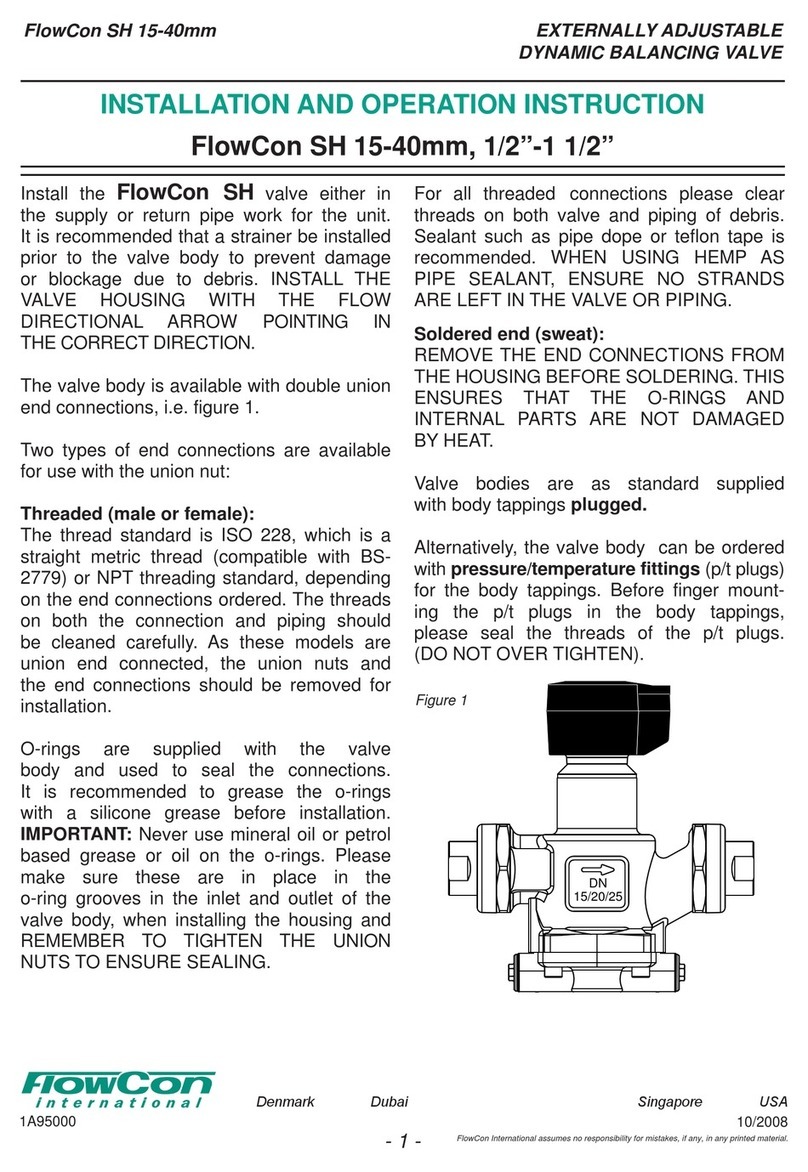
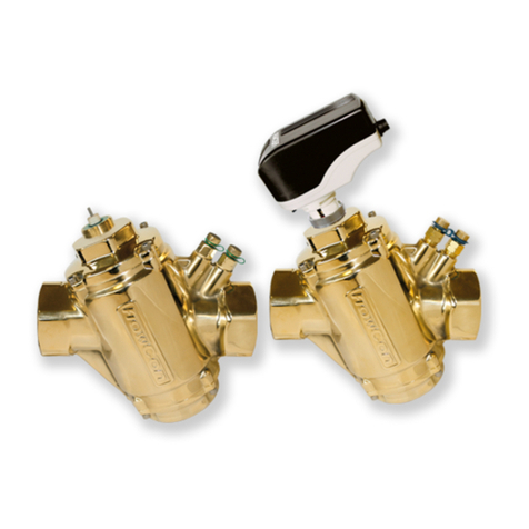
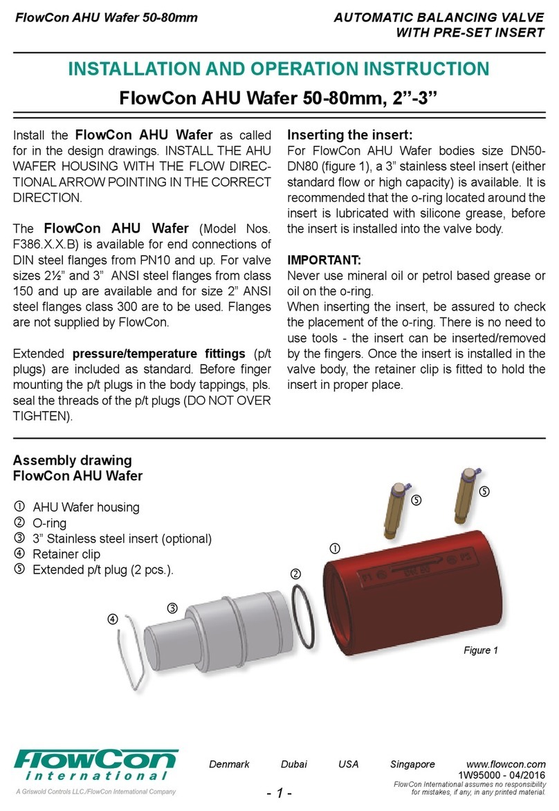
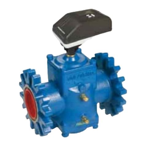
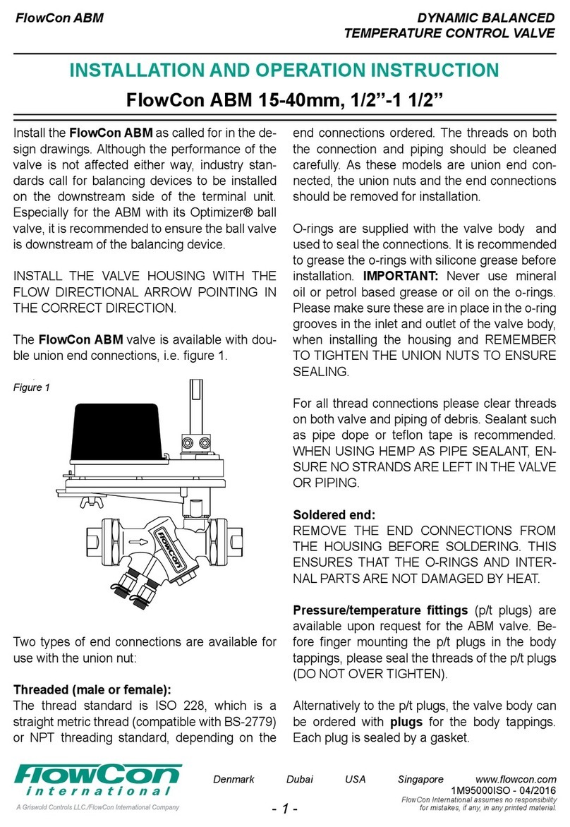
FlowCon FlowCon Green Series Owner's manual

INSTALLATION AND OPERATION INSTRUCTION
INSERT FOR PRESSURE
INDEPENDENT CONTROL VALVE
FlowCon Green
FlowCon International assumes no responsibility
for mistakes, if any, in any printed material.
Denmark Dubai USA Singapore www.owcon.com
1B95090US - 04/2017
- 4 - - 1 -
FlowCon Green 1/2”-1 1/2”
Figure 1
Figure 2
Figure 3
The FlowCon Green inserts are for use with
three different FlowCon valve housings, either:
FlowCon A (1/2” / 3/4” / 1”),
FlowCon AB (1/2” / 3/4” / 1” / 1 1/4”) or
FlowCon ABV (1/2” / 3/4” / 1” / 1 1/4” / 1 1/2”).
Install the selected valve housing as called for in
the design drawings. Although the performance
of the valve is not affected either way, industry
standards call for balancing devices to be in-
stalled on the downstream side of the terminal
unit. Especially for the ABV with its isolation ball
valve, it is recommended to ensure the isolation
valve is downstream of the balancing device.
INSTALL THE VALVE HOUSING WITH THE
FLOW DIRECTIONAL ARROW POINTING IN
THE CORRECT DIRECTION.
The FlowCon A valve (Model Nos.A15.X, A20.X
and A25.I.K) is available with fixed female-
by-female threaded connections, i.e. figure 1.
The thread standard for the A model is either
ISO 228, which is a straight metric thread (com-
patible with BS-2779) or NPT threading stan-
dard, depending on the product number ordered
(except for DN25 which currently is only ISO).
For all threaded connections please clear
threads on both valve and piping of debris.
Sealant such as pipe dope or teflon tape is
recommended. WHEN USING HEMP AS PIPE
SEALANT, ENSURE NO STRANDS ARE LEFT
IN THE VALVE OR PIPING.
The FlowCon AB valve (Model Nos. AB15.X,
AB20.X, AB25.X and AB32.X) is similarly avail-
able with female-by-female threaded connec-
tions, i.e. figure 2.
The thread standard for the AB model is equal
to what is available for the A model.
For all threaded connections please clear
threads on both valve and piping of debris.
Sealant such as pipe dope or teflon tape is
recommended. WHEN USING HEMP AS PIPE
SEALANT, ENSURE NO STRANDS ARE LEFT
IN THE VALVE OR PIPING.
Pressure/temperature fittings (p/t plugs) are
available upon request for the AB valve. Before
finger mounting the p/t plugs in the body tap-
pings, please seal the threads of the p/t plugs
(DO NOT OVER TIGHTEN).
Alternatively to p/t plugs, the valve body can be
ordered with plugs for the body tappings. Each
plug is sealed by a gasket.
The FlowCon ABV valve (Model No. ABV1 and
ABV2) is available with double union end con-
nections, i.e. figure 3.

INSERT FOR PRESSURE
INDEPENDENT CONTROL VALVE
FlowCon Green
FlowCon International assumes no responsibility
for mistakes, if any, in any printed material.
Denmark Dubai USA Singapore www.owcon.com
1B95090US - 04/2017
- 2 -
Two types of end connections are available for
use with the union nut:
Threaded (male or female):
The thread standard is ISO 228 which is a
straight metric thread (compatible with BS-
2779) or NPT threading standard, depending
on the end connections ordered. The threads
on both the connection and piping should be
cleaned carefully. As these models are union
end connected, the union nuts and the end con-
nections should be removed for installation.
O-rings are supplied with the valve body and
used to seal the connections. It is recommend-
ed to grease the o-rings with silicone grease
before installation. IMPORTANT: Never use
mineral oil or petrol based grease or oil on the
o-rings. Please make sure the o-rings are in
place in the o-ring grooves in the inlet and outlet
of the valve body when installing the housing
and REMEMBER TO TIGHTEN THE UNION
NUTS TO ENSURE SEALING.
For all threaded connections please clear
threads on both valve and piping of debris.
Sealant such as pipe dope or teflon tape is
recommended. WHEN USING HEMP AS PIPE
SEALANT, ENSURE NO STRANDS ARE LEFT
IN THE VALVE OR PIPING.
Soldered end (sweat):
REMOVE THE END CONNECTIONS FROM
THE HOUSING BEFORE SOLDERING. THIS
ENSURES THAT THE O-RINGS AND INTER-
NAL PARTS ARE NOT DAMAGED BY HEAT.
Pressure/temperature fittings (p/t plugs) are
available upon request for the ABV valve. Be-
fore finger mounting the p/t plugs in the body
tappings, please seal the threads of the p/t
plugs (DO NOT OVER TIGHTEN).
Alternatively to p/t plugs, the valve body can be
ordered with plugs for the body tappings. Each
plug is sealed by a gasket.
Inserting the insert
Prior to installing the FlowCon Green insert
(supplied from factory in setting 5.0 due to cali-
bration), the system should be properly flushed.
A blank valve cover is available to be installed
during flushing. It is recommended that the o-
rings located around the Green insert and at
the headnut are lubricated with silicone grease,
before the insert is installed into the valve body.
IMPORTANT: Never use mineral oil or petrol
based grease or oil on the o-rings.
The desired flow rate is chosen by adjusting the
flow control insert (turned from setting 1.0 and
up), with a special adjustment key, i.e. figure 4
(page 3). The key is used to adjust the scale on
the top of the insert; the large white are num-
bered 1 through 5 and the red are numbered 0
through 9.
The insert can be installed in the valve
body either before or after setting the
required flow rate. Once the correct
flow rate has been selected and the
insert is fitted in the valve body, then
the actuator is applied.
Please see specific installation instruction for
selected actuator.
General
It is recommended flushing the system before
installing the insert in the valve body. Suitable
flushing caps are available. Water must always
be suitable treated, clean and free of debris. It is
recommended that a strainer be installed prior
to the valve body to prevent damage or block-
age due to debris. Ensure that the valve is not in
the fully closed position when filling the system
with water.
Warranty obligation
Failure to abide by all recommendations as per
this installation and operation instruction will
void warranty.
For latest updates pls. see www.flowcon.com

INSERT FOR PRESSURE
INDEPENDENT CONTROL VALVE
FlowCon Green
FlowCon International assumes no responsibility
for mistakes, if any, in any printed material.
Denmark Dubai USA Singapore www.owcon.com
1B95090US - 04/2017
- 3 -
Accuracy: Greatest of either ±10% of controlled ow rate or ±5% of maximum ow rate.
*at setting 2.6.
FlowCon Green
Setting
Insert size:
20mm · 3/4”
Insert size:
40mm · 1 1/2”
Nominal flow rate
16-200 kPaD
2.3-29 psid
30-400 kPaD
4.4-58 psid
16-400 kPaD*
2.3-58 psid*
Green.0
(grey o-ring)
Green.1
(black o-ring)
Green.2
(black o-ring)
l/sec l/hr GPM l/sec l/hr GPM l/sec l/hr GPM
- - - 0.0178 64 0.282 0.240 865 3.81 1.0
0.0103 37 0.163 0.0393 142 0.624 0.282 1010 4.46 1.1
0.0233 84 0.370 0.0580 209 0.920 0.322 1160 5.10 1.2
0.0322 116 0.510 0.0743 268 1.180 0.361 1300 5.72 1.3
0.0419 151 0.664 0.0887 319 1.41 0.399 1430 6.32 1.4
0.0500 180 0.792 0.102 366 1.61 0.435 1570 6.90 1.5
0.0569 205 0.902 0.113 408 1.80 0.471 1700 7.47 1.6
0.0650 234 1.03 0.124 446 1.96 0.506 1820 8.02 1.7
0.0719 259 1.14 0.134 482 2.12 0.540 1940 8.56 1.8
0.0781 281 1.24 0.143 516 2.27 0.573 2060 9.08 1.9
0.0839 302 1.33 0.152 549 2.42 0.605 2180 9.59 2.0
0.0889 320 1.41 0.161 580 2.56 0.636 2290 10.1 2.1
0.0942 339 1.49 0.170 611 2.69 0.667 2400 10.6 2.2
0.0981 353 1.55 0.178 641 2.82 0.696 2510 11.0 2.3
0.103 371 1.63 0.186 671 2.95 0.725 2610 11.5 2.4
0.106 381 1.68 0.194 700 3.08 0.753 2710 11.9 2.5
0.109 394 1.73 0.202 728 3.21 0.780 2810 12.4 2.6
0.113 406 1.79 0.210 756 3.33 0.807 2900 12.8 2.7
0.115 414 1.82 0.218 783 3.45 0.832 3000 13.2 2.8
0.119 428 1.88 0.225 810 3.56 0.858 3090 13.6 2.9
0.122 439 1.93 0.232 835 3.68 0.882 3180 14.0 3.0
0.125 449 1.98 0.239 860 3.79 0.906 3260 14.4 3.1
0.127 458 2.02 0.245 883 3.89 0.930 3350 14.7 3.2
0.130 468 2.06 0.252 906 3.99 0.953 3430 15.1 3.3
0.133 477 2.10 0.257 927 4.08 0.975 3510 15.5 3.4
0.135 486 2.14 0.263 946 4.17 0.997 3590 15.8 3.5
0.137 494 2.17 0.268 965 4.25 1.02 3670 16.1 3.6
0.140 503 2.21 0.273 982 4.32 1.04 3740 16.5 3.7
0.142 511 2.25 0.277 998 4.39 1.06 3820 16.8 3.8
0.144 518 2.28 0.281 1010 4.46 1.08 3890 17.1 3.9
0.146 526 2.31 0.285 1020 4.51 1.10 3960 17.4 4.0
0.148 532 2.34 0.288 1040 4.57 1.12 4030 17.7 4.1
0.149 538 2.37 0.291 1050 4.61 1.14 4100 18.1 4.2
0.151 544 2.39 0.294 1060 4.66 1.16 4170 18.4 4.3
0.153 549 2.42 0.296 1070 4.70 1.18 4240 18.7 4.4
0.154 553 2.43 0.299 1080 4.73 1.20 4300 19.0 4.5
0.155 559 2.46 0.301 1080 4.77 1.21 4370 19.2 4.6
0.156 563 2.48 0.303 1090 4.80 1.23 4440 19.5 4.7
0.158 567 2.50 0.305 1100 4.83 1.25 4500 19.8 4.8
0.159 571 2.51 0.307 1100 4.86 1.27 4570 20.1 4.9
0.160 575 2.53 0.308 1110 4.89 1.29 4630 20.4 5.0
Figure 4

INSERT FOR PRESSURE
INDEPENDENT CONTROL VALVE
FlowCon Green
FlowCon International assumes no responsibility
for mistakes, if any, in any printed material.
Denmark Dubai USA Singapore www.owcon.com
1B95090US - 04/2017
- 4 -
Figure 6
B
C
Fa
A
DN
25/32/40
F
D1 D2
C
EE
Figure 5
A 20625-00
FT.0.3
1403
MadeinGermany
230 V NC 1,2 W
A
B
C
D1 D2
E E
C
F
Fa
A 20625-00
FT.0.3
1403
MadeinGermany
230 V NC 1,2 W
Assembly drawing
FlowCon Green (3/4”)
in ABV1 housing
A: Valve housing
(here FlowCon ABV1,
incl. o-rings for end conn.)
B: Green insert (3/4”)
C: Adjustment keys
D1: P/t plug (2 pcs.)
D2: Plug and gasket (2 of each)
E: Union end connections
F: FlowCon FT actuator
Fa: Adaptor ring.
Assembly drawing
FlowCon Green (1 1/2”)
in ABV2 housing
A: Valve housing (here FlowCon ABV2,
incl. o-rings for end connections)
B: Green insert (1 1/2”)
C: Adjustment keys
D1: P/t plug (2 pcs.)
D2: Plug and gasket (2 of each)
E: Union end conn.
F: Actuator
(here FN.0.X-type)
Fa: Valve adaptor.
This manual suits for next models
3
Other FlowCon Control Unit manuals
FlowCon
FlowCon Green Owner's manual
FlowCon
FlowCon Green.3 DN40 Owner's manual
FlowCon
FlowCon EVS User manual
FlowCon
FlowCon SM 50-250mm Owner's manual
FlowCon
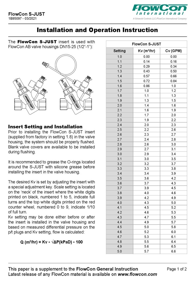
FlowCon S-JUST Owner's manual
FlowCon
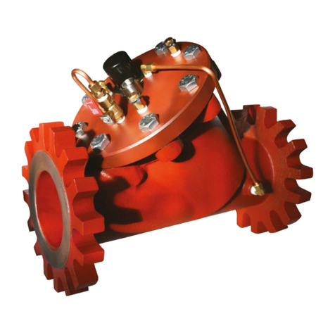
FlowCon PIM-DP User manual
FlowCon
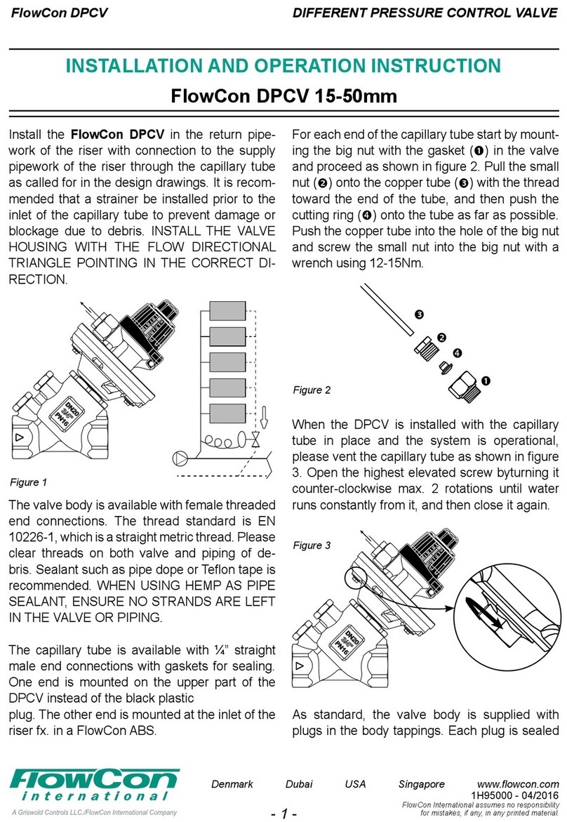
FlowCon DPCV Owner's manual
FlowCon
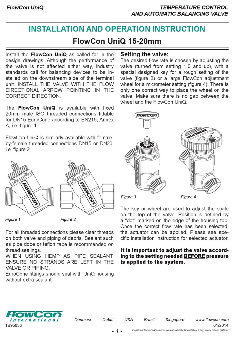
FlowCon UniQ Owner's manual
FlowCon
FlowCon SM.1.1 Owner's manual
FlowCon
FlowCon Green Owner's manual
