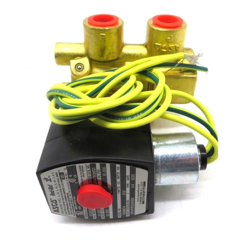
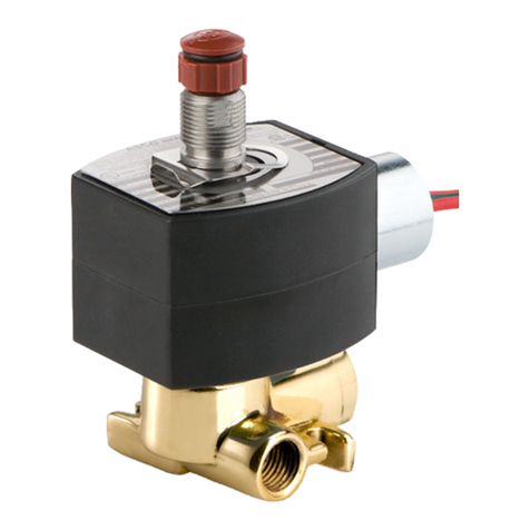
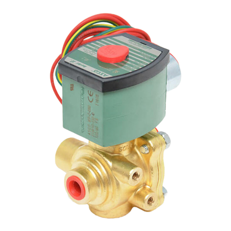
Asco 8345 Series Installation and operating instructions
Other Asco Control Unit manuals
Asco
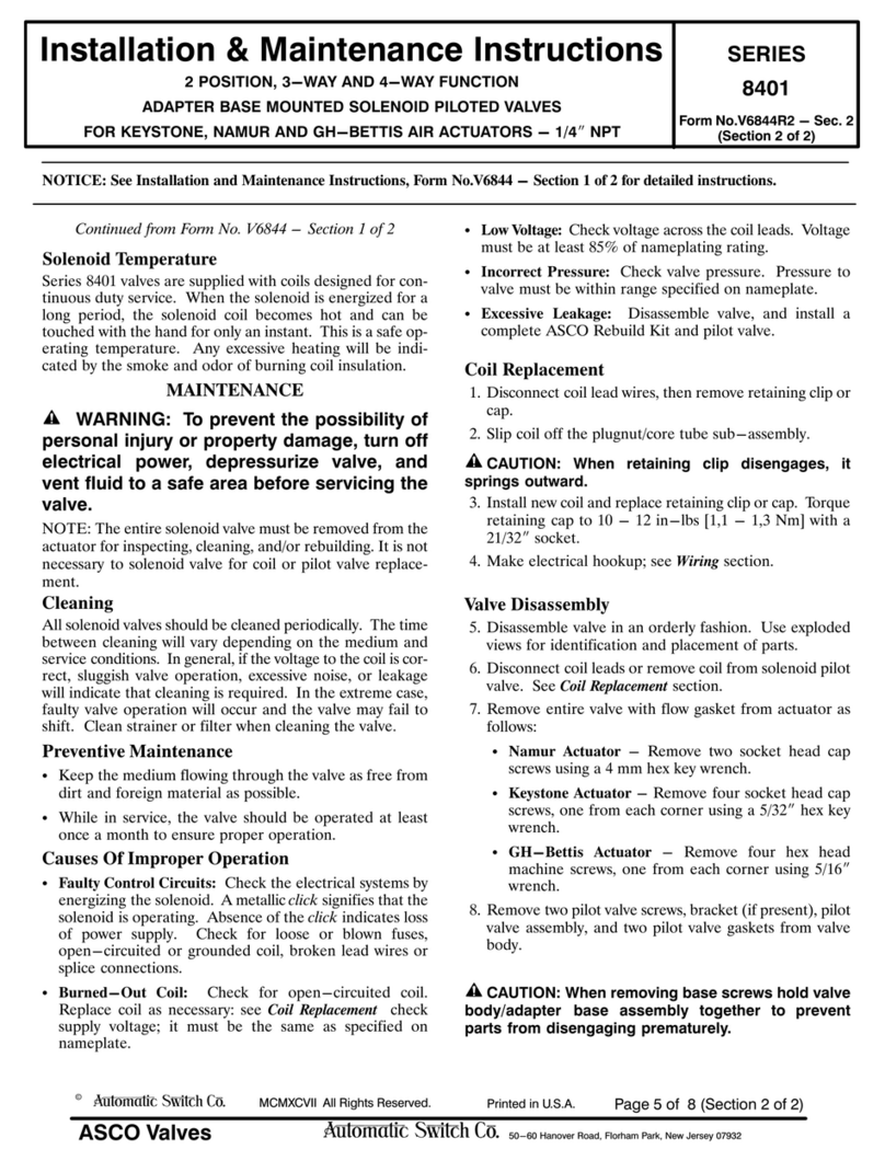
Asco 8401 Series User manual

Asco
Asco 8267 Series Installation and operating instructions
Asco
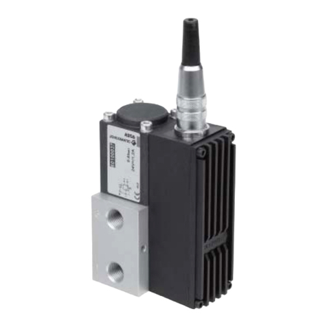
Asco JOUCOMATIC SENTRONIC 601 Series User manual
Asco
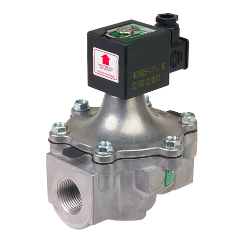
Asco 215 Series User manual
Asco
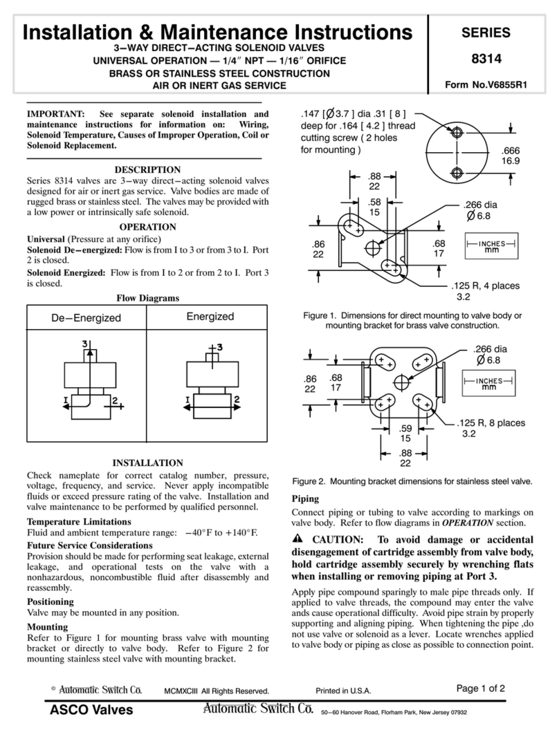
Asco 8314 Series Installation and operating instructions
Asco
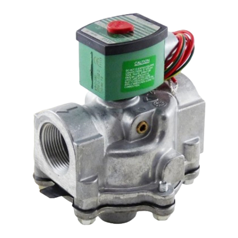
Asco 8214G54 Installation and operating instructions
Asco
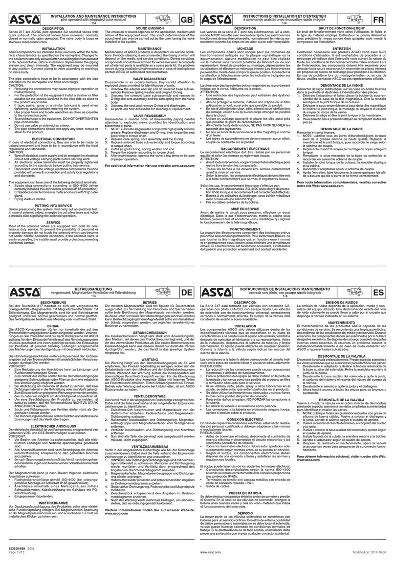
Asco 317 Series User manual
Asco
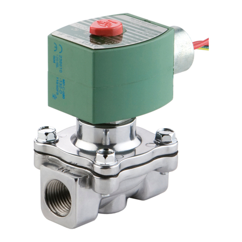
Asco 8215 Series Installation and operating instructions
Asco
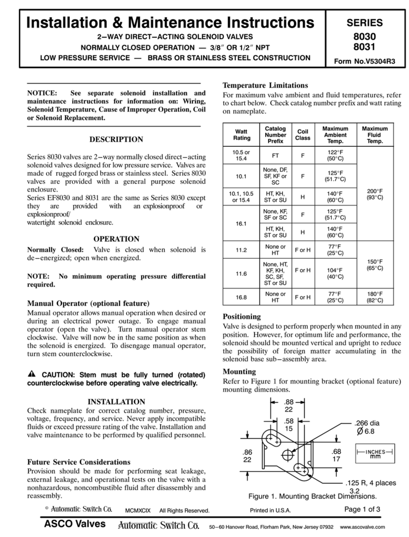
Asco 8030 Series Installation and operating instructions
Asco
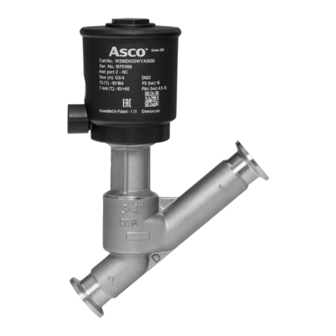
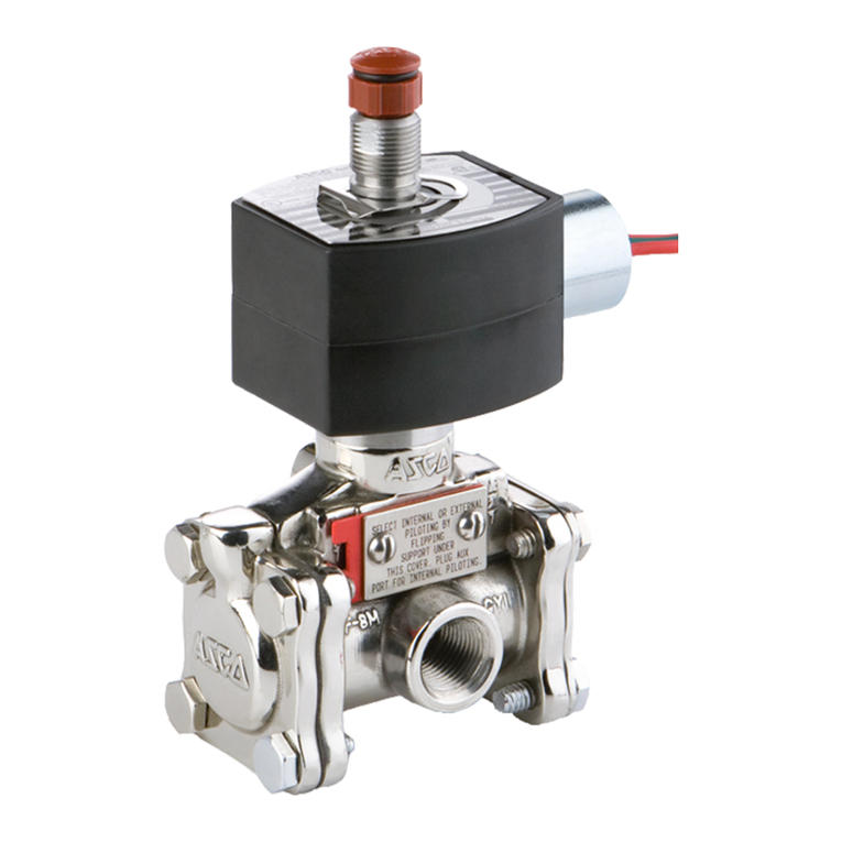
Asco 290 Series User manual
Asco
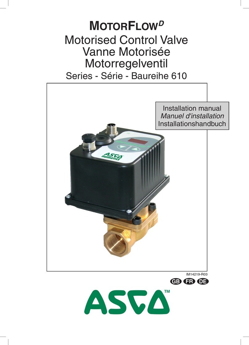
Asco 8316 Series Installation and operating instructions
Asco
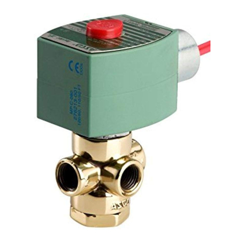
Asco MotorFlowD 610 Series User manual
Asco
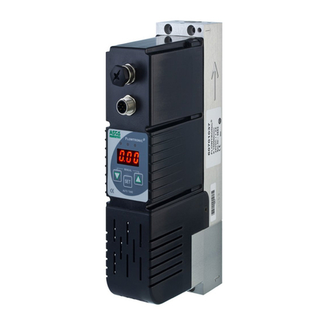
Asco 8320 Series Installation and operating instructions
Asco
Asco JOUCOMATIC FLOWTRONICD 607 User manual
Asco
Asco 8210 series User manual

Asco
Asco 290 Series User manual

Asco
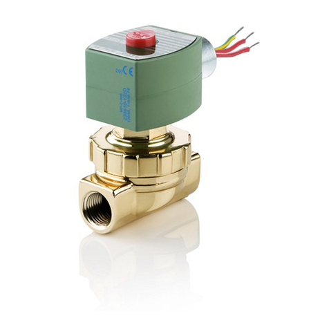
Asco RedHat 8223 Series Installation and operating instructions
Asco
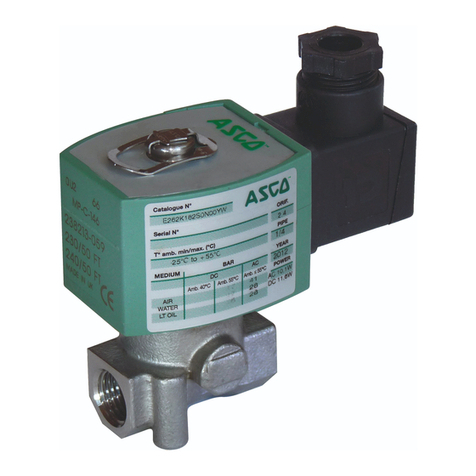
Asco 262 Series User manual
Asco
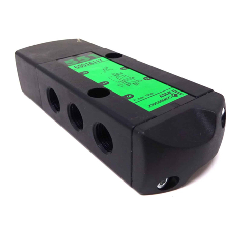
Asco 551 Series User manual
Asco
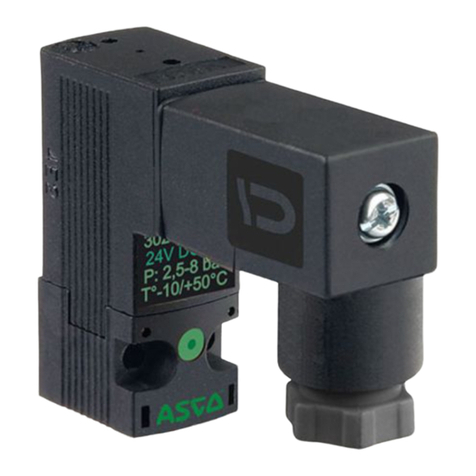
Asco 302 Series User manual
Popular Control Unit manuals by other brands

Festo
Festo Compact Performance CP-FB6-E Brief description

Elo TouchSystems
Elo TouchSystems DMS-SA19P-EXTME Quick installation guide

JS Automation
JS Automation MPC3034A user manual

JAUDT
JAUDT SW GII 6406 Series Translation of the original operating instructions

Spektrum
Spektrum Air Module System manual

BOC Edwards
BOC Edwards Q Series instruction manual

KHADAS
KHADAS BT Magic quick start

Etherma
Etherma eNEXHO-IL Assembly and operating instructions

PMFoundations
PMFoundations Attenuverter Assembly guide

GEA
GEA VARIVENT Operating instruction

Walther Systemtechnik
Walther Systemtechnik VMS-05 Assembly instructions

Altronix
Altronix LINQ8PD Installation and programming manual
