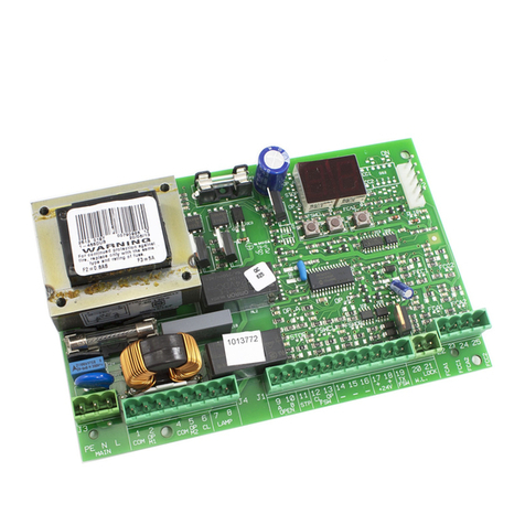
FAAC E145S User manual

E145S Quick
Start Guide

Page | 1
Installation Sequence ........................................................................................................................................................ 2
E145S LED Display at first Power On ................................................................................................................................. 3
J11 Terminals ................................................................................................................................................................ 3
J3 Terminals .................................................................................................................................................................. 3
Electrical Connections ....................................................................................................................................................... 4
Connection of Traditional Photocells ............................................................................................................................ 4
Connection of FAAC BUS 2Easy Photocells ................................................................................................................... 5
Connection of FAAC BUS 2easy Safecoders and S800 Encoders .................................................................................. 5
Verification of BUS 2easy Connections on J10 Terminal .............................................................................................. 6
E145S Control Board Programming .................................................................................................................................. 6
Basic Programming ....................................................................................................................................................... 7
Set-Up – Time Learning (tL – function) ......................................................................................................................... 8
Advanced Programming ................................................................................................................................................ 9
E145S Signalling Errors and Alarms ................................................................................................................................. 10
E145S Operating Logics ................................................................................................................................................... 10
Programming Remote Controls using the XF Receiver and OmniDec ............................................................................ 11
Programming a new remote control to a new E145S System .................................................................................... 11
Programming a new remote control from a working master remote control ........................................................... 11
Tutorial Videos available for programming remote controls ..................................................................................... 11
These instructions are to be considered as a rapid guide for installation and to confirm the correct handing and polarity
of the motors. They can also be used to confirm the operating logics before additional safety devices are fitted to the
system as specified by the Risk Assessment undertaken by the installer. The installer should still familiarise
themselves with the full manual and the safety information contained within. (available at
https://www.faac.co.uk/accessories-and-control-boards/control-boards/for-swing-gates/e145S-control-board)

Page | 2
Installation Sequence
1. Perform A Risk Assessment for the system and resolve by design as many risks as possible
2. Secure the card into a suitable enclosure
3. Mount the motors as detailed in their relevant instructions
4. Use suitable cabling for the motors and accessories (BUS devices must be wired using a
minimum 2 core, 0.5mm multi-stranded screened cable (the screen MUST be attached to the
Earth Terminal)
5. Wire the electronic control board as per Page 4 for the motors and power supply
6. Please note that J3 Terminal block comes with the Stop, FSW CL and FSW OP pre-linked for
first run-up of the system as shown on Page 3
7. Power up the E145 Board (please note that the board will take 5-10 seconds to boot-up)
8. Verify the status of the LED’s and Display are as per Page 3
9. Depending on the installation, verify that the LED’s on the encoders correspond to those
described on Page 5
10. Wire in an OP-A trigger as per Page 4, alternatively program a remote control as shown on
Page 11.
11. Familiarise yourself with how to program the E145S control board as per Page 6
12. Begin Basic Programming of the E145S on Page 7
a. If Hydraulic motors are used, please note that “F1” and “F2” MUST be set to “50” as
torque adjustment is performed on the motors as detailed in the motor manual
b. Check Rotation of the motors by using Function “n1” and “n2” for motor 1 and 2
respectively as shown on Page 7
c. If using encoders, “EN” must be set to “y” and “bu” function should be followed as
shown on Page 7
d. Verify that the Gates are in the closed position as detailed on Page 8
e. Run Time Learning – “tL” function and follow procedure as detailed on Page 8
13. Provide an opening command to verify that the system works correctly
14. Adjust Operating Logic according to the customer requirement, brief details on Page 10
15. Connect Safety Devices to the system as deemed required by the Risk Assessment carried
out previously
a. Hard Wired Safety Edges can be wired in J11 Terminals as per Page 3 and correct
“So” or “Sc” function adjusted to match on Page 7
b. Wireless Safety Edges can be connected via the BUS 2easy connection if using the
FAAC XTR and XTS Wireless Receiver system, the “bu” function must also be re-
addressed as shown on Page 7
c. If not using the FAAC XTR and XTS System please treat the input on J11 as required
by the Wireless Safety Edge system being used
d. Traditional Photocells can be wired and configured as per Page 4
e. FAAC BUS 2easy Photocells can be wired and configured as per Page 5, the “bu”
function must also be re-addressed as shown on Page 7
f. XGuard Laser Curtains would be configured as Traditional Photocells in 14.c
16. Connect any additional activation commands as per Page 4
17. If using either Safety Edges or Inherent Obstacle Detection as part of the Risk Assessment,
there are useful Functions that can be modified to assist in attaining compliance on Page 9
18. If using XGuard Laser Curtains please test these in accordance with BS EN 12445/12453
19. Hand over all relevant documentation to the end customer as required by the Technical File
and the Supply of Machinery (Safety) Regulations 2008

Page | 3
J11 Terminals
E145
S
LED Display at first Power On
J3 Terminals
The new J11 Terminal to allow the direct connection of resistive safety edges or N/C safety inputs comes pre-linked and
configured to N/C setting, hence the relevant EDGE 1 or EDGE 2 LED being lit on first Power On.
DL7, DL6 and DL5 will only be illuminated if the following terminals are linked out (please note that the board comes with
links in place). The links are just to be used for test purposes only and safety devices should be wired in, as detailed in the
instructions further below. In no circumstances should the system be handed over to the end user with these links still in
place unless it is being controlled via Dead-Man operation and by trained users only.

Page | 4
The E145S Control Board allows for the use of traditional photocells (n/c with relay). Below is a layout drawing showing the
basic positions normally covered. The wiring diagram is for Fail-Safe enabled photocells. In order to comply with the standards,
all devices used for safety should either have a circuit monitored by the control board or be self-monitoring. FAAC Control
boards are able to perform the monitoring by the use of a Fail-Safe function, whereby the test negative is momentarily dropped
(please note that this may not be compatible with non-FAAC equipment). This function is enabled by entering Advanced
Programming (detailed below) and setting function o1 to 01.
Electrical Connectio
ns
Connection of Traditional Photocells

Page | 5
The E145S Control Board also allows for the use of FAAC BUS 2easy photocells which allow for simpler cabling and a reduced
power consumption. FAAC BUS 2easy photocells also remove the need for additional wiring for a monitoring circuit as it is
carried through our proprietary FAAC BUS 2easycommunication protocol (Please note that FAAC BUS photocells are only
compatible with FAAC Control Boards and those using the BUS Terminal or using the BUS Relay Interface Board).
Connection of FAAC BUS 2Easy Photocells
Connection of FAAC BUS 2easy Safecoders and S800 Encoders
The E145S Control Board also allows for the use of FAAC BUS 2easy Safecoders and the S800 Encoders on the 230v versions.
This allows for the control board to have positional accuracy and allows for the possibility of inherent obstacle detection (Force
Testing with the use a calibrated instrument to BS EN 12445/12453 norms (such as the Microtronics Blueforce Tester, available
from FAAC UK) will be required to confirm suitability but please note that additional devices maybe required such as Safety
Edges).

Page | 6
The function is
displayed only while
the button is pressed
The J10 Terminal on the E145S Control Board has two diagnostic LED’s (DL15 – Red and DL14 – Green). These LED’s assist in
ensuring that any devices connected on the FAAC BUS 2easy network are installed correctly.
Verification of BUS 2easy Connections on J10 Terminal
Programming is split over two levels:
Basic Programming
Advanced Programming
E145S Control Board Programming

Page | 7
Basic Programming

Page | 8
Set-Up – Time Learning (tL – function)

Page | 9
Advanced Programming
Out 1 Options available
Useful Functions to protect against the risk of
impact/crushing on the main edge
Please note that if you are using either safety edges or
inherent obstacle detection (such as encoders), then
you must a Force Tester calibrated to BS EN 12443/
12453 norms and the results must fall within the
values there in and in accordance with the risk
assessment already undertaken.

Page | 10
E145S Signalling Errors and Alarms
E145S Operating Logics
The table below shows only the most commonly used Operating Logics on our control board. For further details, please refer
to the main manual for the full list.

Page | 11
Programming Remote Controls using the XF Receiver and OmniDec
Programming a new remote control to a new E145S System
Tutorial Videos available for programming remote controls
FAAC UK have created tutorial videos to assist the installer in the programming of remote controls. Please use the link below
to navigate straight to our “YouTube” Channel or use your preferred web browser and navigate to “youTube.com” and search
for “FAAC UK” and select our channel and look for the videos required.
https://www.youtube.com/user/FAACUK
Programming a new remote control from a working master remote control
Other manuals for E145S
1
Table of contents
Other FAAC Control Unit manuals